

Honeywell V4055A, V4055D, V4055B, V4055E User Manual
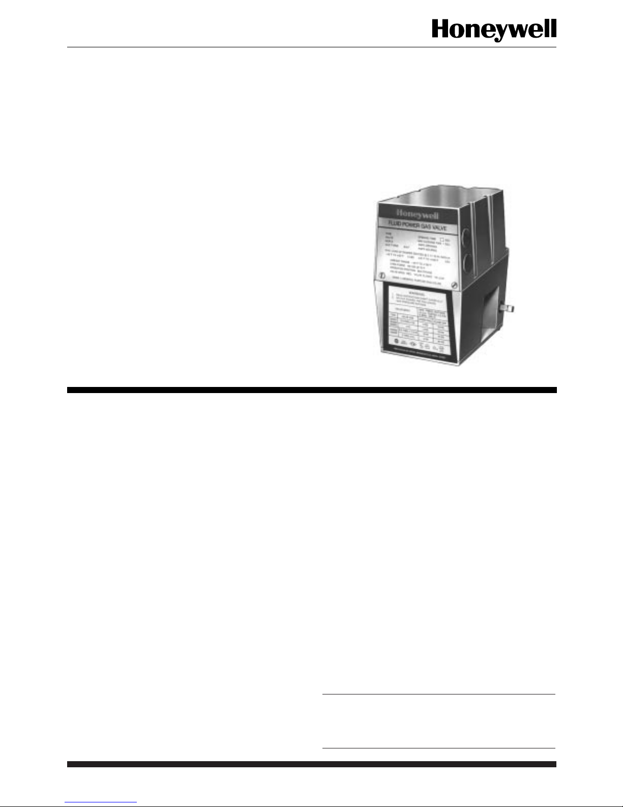
On-Off Fluid Power
Gas Valve Actuator
The V4055 Gas Valve Actuator in combination
with a V5055 Gas Valve controls the gas supply to
commercial and industrial burners.
V4055A,B,D,E
■ The V4055 Actuator, when used with the V5034 or
V5055 Valve, is rated for final safety shutoff service.
■ The V4055 Actuator may be used with the character-
ized guide model of the V5055 gas valve to enhance
lightoff smoothness.
■ The standard model has an opening time of 26 sec at
60 Hz, or 32 sec at 50 Hz. A fast-opening model, is
available with timings of 13 sec at 60 Hz, or 16 sec at
50 Hz.
■ Maximum closing time is 1 sec, which meets code/
standard/insurer requirements.
■ Models with damper shaft available, with or without
spring return; shaft extends out both sides and rides
in Teflon-like, Delrin bushings; used with standard
7616BR Damper Crank Arm.
■ Red OPEN indicator attached to the actuator stem
shows when valve is even slightly open; yellow
SHUT indicator on valve stem shows only when gas
valve is fully closed.
■ Ambient temperature rating is -40°F to 150°F
[-40°C to 66°C] for 60 Hz models; -10°F to 158°F
[-23°C to 70°C] for 50 Hz and 50/60 Hz models.
■ Valve and actuator combination may be mounted in
any position.
■ Models available with factory installed SPDT field
adjustable auxiliary switch. Field addable auxiliary
switch kits are also available.
■ Standard enclosure meets NEMA 1 general purpose
requirements; models available with NEMA 4
weather proof enclosure.
■ V4055D and high pressure V4055E with proof-ofclosure switch and V5055C or E with valve seal
overtravel interlock (double seal) to meet specific
code/standard/insurer requirements.
CONTENTS
Specifications .................................................2
Ordering Information..................................... 2
Installation .....................................................4
Checkout and Service .....................................8
1 60-2309—8 F.P. • Rev. 10-94 • ©Honeywell Inc. 1994 • Form Number 60-2309—8

V4055A,B,D,E
SPECIFICATIONS • ORDERING INFORMATION
Specifications
MODELS:
NOMINAL OPENING TIME (SECONDS):
V4055A actuator with V5055 gas valves provide on-off
control of fuel. With proper adapter (see Accessories),
it replaces the V4034 actuator on a V5034 gas valve.
V4055B is a high pressure model of the V4055A.
V4055D is identical to the V4055A but incorporates a
proof-of-closure switch. Used with V5055C (double
seal) for valve seal overtravel interlock.
V4055E is identical to V4055B but incorporates a proof-
of-closure switch. Used with V5055E (double seal)
for valve seal overtravel interlock.
NEMA 4 (weatherproof) models available.
Model 50 Hz 60 Hz
Standard 32 26
Fast-opening 16 13
MAXIMUM CLOSING TIME: One second when de-ener-
gized.
AMBIENT OPERATING TEMPERATURE RATING:
60 Hz MODELS: -40°F to 150°F [-40°C to 66°C].
50 Hz, 50/60 HZ MODELS: -10°F to 158°F [-23°C to
70°C].
MOUNTING: V4055 attached directly to V5055 valve with
two set screws positioned with 90 degrees separation.
PRESSURE RATINGS:
Combination is multipoise.
PRESSURE RATINGS OF VALVE-ACTUATOR COMBINATIONS.
Actuator
V4055A,D
b
Diff
Valve psi kPa psi kPa psi kPa psi kPa
V5055A,C
3/4 to 3 in.
V5055A,C
4 in.
V5055B
3/4 to 3 in.
V5055B
4 in.
V5055D,E
3/4, 1-1/4, 1-1/2 in.
V5055D,E
2, 2-1/2, 3 in.
a
Use a V4055D or V4055E (with proof-of-closure switch) with a V5055C or V5055E (with double seal) for valve seal
5 34.5 15 103.4 15 103.4 15 103.4
3 20.7 15 103.4 5 34.5 15 103.4
5 34.5 15 103.4 15 103.4 15 103.4
3 20.7 15 103.4 5 34.5 15 103.4
5 34.5 75 517.1 25 172.4 75 517.1
5 34.5 45 310.3 15 103.4 45 310.3
a
Closeoff
V4055B,E
c
Diff
b
a
Closeoff
c
overtravel interlock.
b
Maximum operating pressure differential.
c
Maximum closeoff pressure without seat leakage. This is the maximum allowable pressure drop to which a valve may be
subjected while fully closed, and is independent of the valve body rating.
When purchasing replacement and modernization products from your TRADELINE® wholesaler or distributor, refer to the Tradeline
Catalog or price sheets for complete ordering number, or specify—
1. Order number. 4. Damper shaft, with or without return spring, if required.
2. Voltage and frequency. 5. NEMA 4 enclosure, if required.
3. Standard or fast opening time. 6. Accessories, if desired.
If you have additional questions, need further information, or would like to comment on our products or services, please write or phone:
1. Your local Home and Building Control Sales Office (please check the white pages of your phone directory).
2. Home and Building Control Customer Logistics
Honeywell, Inc., 1885 Douglas Drive North
Minneapolis, Minnesota 55422-4386 (612) 951-1000
In Canada—Honeywell Limited/Honeywell Limitée, 740 Ellesmere Road, Scarborough, Ontario M1P2V9. International Sales and
Service Offices in all principal cities of the world. Manufacturing in Australia, Canada, Finland, France, Germany, Japan, Mexico,
Netherlands, Spain, Taiwan, United Kingdom, U.S.A.
60-2309—8 2
Ordering Information

V4055A,B,D,E
SPECIFICATIONS
ELECTRICAL RATINGS: V4055A,D:
Voltage and Opening (Standard) Opening (Fast) Holding
Frequency Inrush W A VA Inrush W A VA W A VA
100/50-60
100/50-60
a
b
– 43.0 0.91 91 – 58.0 1.30 130 10.4 0.16 16
– 33.0 0.67 67 – 43.0 0.91 91 8.4 0.14 14
120/60 3.9 50.0 0.94 115 5.4 71.0 1.33 160 9.5 0.12 14
200/50-60
200/50-60
a
b
– 68.0 0.79 158 – 88.0 1.10 220 10.6 0.09 18
– 48.0 0.52 104 – 63.0 0.72 144 9.0 0.07 14
220/50 1.6 55.5 0.55 121 3.0 76.0 0.80 176 9.0 0.06 14
240/50 – 81.5 0.79 190 – 95.0 1.00 240 9.1 0.06 14
240/60 2.6 51.0 0.45 115 4.0 71.5 0.68 160 9.2 0.06 14
a
50 Hz power supply.
b
60 Hz power supply.
V4055B,E–120V, 60 Hz.
Opening—60W 0.94A (5.4A inrush), 115 VA.
Holding—9.5W, 0.16A, 19 VA.
AUXILIARY SWITCH AND PROOF-OF-CLOSURE
SWITCH RATINGS: 1/2 hp [0.37 kW]a:
MOUNTING DIMENSIONS: See Fig. 1.
DAMPER SHAFT: Models available with or without inte-
gral damper shaft. Shaft is 3/8 in. [9.5 mm] square, for use
with 7616 BR Damper Crank Arm (not included). Models available with or without damper shaft return spring.
MAXIMUM DAMPER SHAFT ROTATION: 52 angular
Load 120V 240V
Full Load 9.8A 4.9A
Locked Rotor 58.8A 29.4A
a
Maximum total connected power to both switches (if used)
is 1800 VA.
degrees.
DAMPER SHAFT MAXIMUM FORCE A 2-11/16 in.
[68.3 mm] RADIUS FOR 7616 BR DAMPER CRANK
ARM (ordered separately):
NOTE: Damper shaft drives damper crank arm in one direc-
tion only; optional return spring is available on damper
shaft to turn damper crank arm in opposite direction.
-40°F to 20°F [-40°C to -7°C] 20°F to 150°F [-7°C to 66°C]
V4055 Model lb N lb N
Without return spring 5 22.2 20 89.0
With return spring 5 22.2 10 44.5
APPROVALS:
Underwriters Laboratories Inc. Listed: File No. MH1639,
Guide No. YIOZ.
Factory Mutual Approved.
International Approval Services (IAS, a joint venture of
AGA and CGA): 60 Hz only.
British Gas Corporation and Dutch Gas Institute Ap-
proved:
V4055 with several V5055A and V5055B models.
V4055D with V5055C models with an internal screen.
ACCESSORIES:
133533A Short Stem Adapter for mounting actuator on
133534A Long Stem Adapter for mounting actuator on
V5034 valve.
133568 Auxiliary Switch Bag Assembly.
133569 Valve-Closed Indication Switch Bag Assembly
(do not use with V5034 valve body).
7616BR Damper Crank Arm (damper arm and clip).
Q5055A1001 Adapter Assembly: Adapts ITT General
V710 Gas Valve to accept Honeywell gas valve
actuators. Replaces ITT General AH2 gas valve
actuators.
AVAILABLE MODELS:
V4055 with NEMA 4 enclosure (weatherproof).
V5034 valve.
3 60-2309—8
V4055A,B,D,E
INSTALLATION
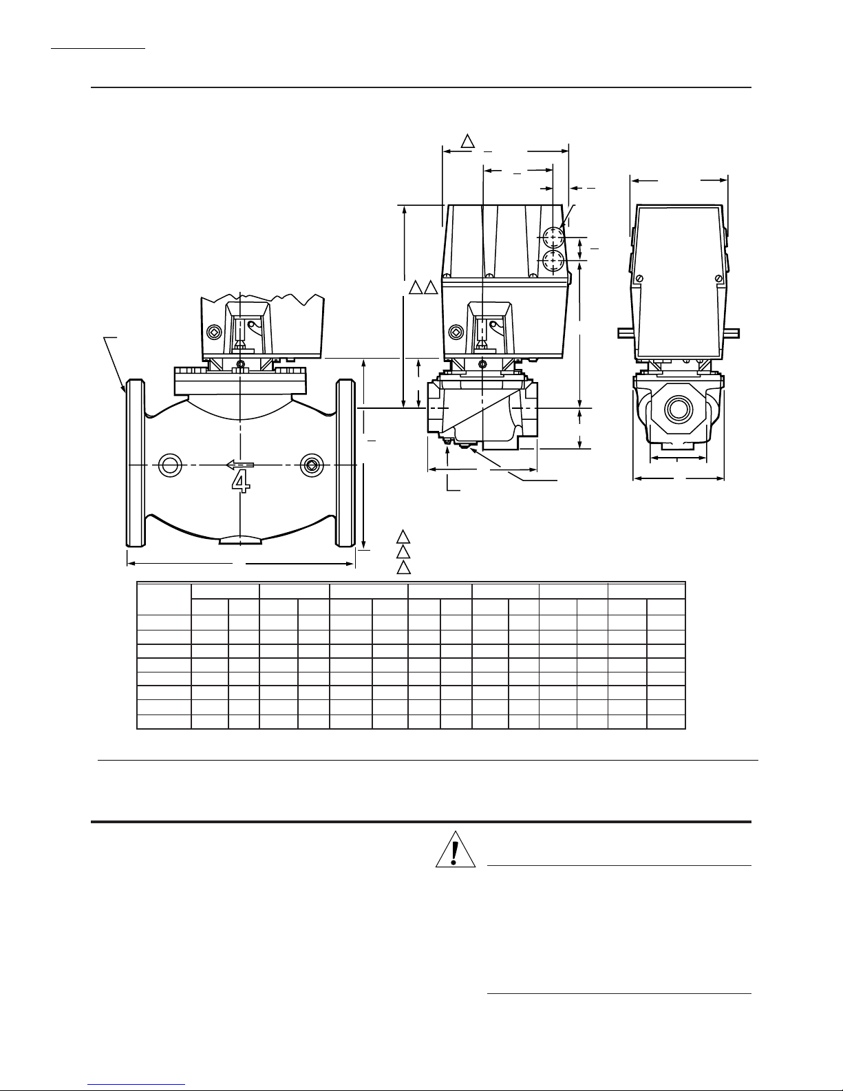
Fig. 1—Approximate Mounting Dimensions of V4055 Actuators and V5055 Valves, in in. [mm].
2
3
[171.5]
6
4
23
3
32
[94.5]
1
A
3
27
[21.4]
32
KNOCKOUT
FOR1/2 INCH
CONDUIT (4)
9
1
32
[32.5]
5 [127.0]
3/4 (19.1) BOLT
HOLES (8)
ON 3-3/4 [95.3]
RADIUS
VALVE SIZE
INCH
3/4
1
1-1/4
1-1/2
2
2-1/2
3
4
DIM A
IN. MM
11-1/8
11-1/8
11-1/8
11-1/8
11-1/4
11-3/4
11-3/4
14-1/8
D
282.6
282.6
282.6
282.6
285.8
298.5
298.5
358.8
DIM B
IN. MM
2-3/4
2-3/4
2-3/4
2-3/4
2-7/8
3-3/8
3-3/8
5-13/16
69.9
69.9
69.9
69.9
73.0
85.7
85.7
147.6
9
[233.4]
DIM C
IN. MM
8-3/16
8-3/16
8-3/16
8-3/16
8-5/16
8-13/16
8-13/16
11-7/32
C
B
3
16
D
1/4 INCH NPT
DOWNSTREAM TAP
AND PLUG
1
ALLOW 4 IN. [101.6 MM] CLEARANCE FOR ACTUATOR REMOVAL.
2
ADD 1/8 IN. [13.2 MM] TO DIMENSION FOR MODELS WITH NEMA 4 ENCLOSURE.
3
ADD 1/4 IN. [6.4MM] TO DIMENSION A FOR MODELS WITH NEMA 4 ENCLOSURE.
208.0
208.0
208.0
208.0
211.1
223.8
223.8
285.0
DIM D
IN. MM
5-3/4
5-3/4
5-3/4
5-3/4
8-3/8
9-1/4
9-1/4
12-1/2
146.1
146.1
146.1
146.1
212.7
235.0
235.0
317.5
DIM E
IN. MM
2-1/4
2-1/4
2-1/4
2-1/4
2-3/4
2-3/4
2-3/4
4-5/8
57.2
57.2
57.2
57.2
69.9
69.9
69.9
117.5
E
1/4 INCH NPT
UPSTREAM TAP
AND PLUG (1/4 BSP
ON INTERNATIONAL
MODELS)
DIM F
IN. MM
4-13/16
122.2
4-13/16
122.2
4-13/16
122.2
4-13/16
122.2
7-19/32
192.9
7-19/32
192.9
7-19/32
192.9
—
—
OCTAGON
IN. MM
2-13/16
2-13/16
2-13/16
2-13/16
3-1/2
4-1/2
4-1/2
—
OCTAGON
F
71.4
71.4
71.4
71.4
88.9
114.3
114.3
—
M7332
WHEN INSTALLING THIS PRODUCT . . .
1. Read these instructions carefully. Failure to follow
them could damage the product or cause a hazardous
condition.
2. Check the ratings given in the instructions and on the
product to make sure the product is suitable for your
application.
3. Installer must be a trained, experienced, flame safeguard control technician.
4. After installation is complete, check out product operation as provided in these instructions.
60-2309—8 4
Installation
CAUTION
1. Disconnect power supply before making wiring
connections to prevent electrical shock and
equipment damage.
2. Voltage and frequency of the power supply
connected to this control must agree with those
marked on the device.
3. Maximum total connected load to both switches
(if used) must not exceed 1800 VA.
V4055A,B,D,E
INSTALLATION
INSTALL VALVE
The actuator is mounted directly on the valve bonnet
after the valve is installed in the gas supply line. Refer to the
instructions packed with the gas valve for installation details. When installing the valve, assure that:
1. Sufficient clearance is left for installation and service
of the actuator.
2. Ambient temperatures at the valve location will re-
main within -40° to 150°F [-40°C to 66°C] or -10°F to 158°F
[-23°C to 70°C] (see Specifications section).
3. Position of the valve permits hookup to the damper if
one is controlled.
INSTALL ACCESSORY SWITCHES (IF NEEDED)
A spdt auxiliary switch may be installed to operate a
load up to 1/2 hp [0.37 kW]. The switch may be adjusted to
operate at any point in the valve stroke.
A proof-of-closure switch may also be installed on any
V4055 actuator to provide a valve seal overtravel interlock
when used with a V5055C or E valve (with double seal).
The spdt proof-of-closure switch is installed to make or
break a circuit when the valve is in the closed position. The
switch is not adjustable.
NOTE: Mark the actuator or valve to indicate any changes
made.
4. Insert the proof-of-closure switch in the position shown
in Fig. 2. The switch mounts against the side of the actuator
housing. The mounting holes are spaced to mount the switch
only in the correct position. Fasten with two screws through
the actuator base. The proof-of-closure switch is not adjustable.
5. If only one switch is used, install the narrow barrier
included with the switch in the unused space.
6. Mount the actuator before making wiring connections
and adjustments to the auxiliary switch.
MOUNT ACTUATOR ON VALVE
Check the final position of the valve body to be sure that
the actuator will be in the proper position when mounted on
the valve. This is especially important if the actuator is used
to drive a damper.
If two smaller sized valves are mounted very closely
together, as in an Industrial Risk Insurers type valve train, it
may be necessary to mount the actuator off center to
provide adequate clearance.
Slip the bottom collar of the actuator over the valve
bonnet assembly. Rotate the actuator to the desired position and use a 5/32 inch Allen wrench to securely tighten
the two set screws. (50 to 60 lb/in [5.7 to 6.8 Nm]).
Connect the damper linkage, if used. Refer to the instructions packed with the damper arm.
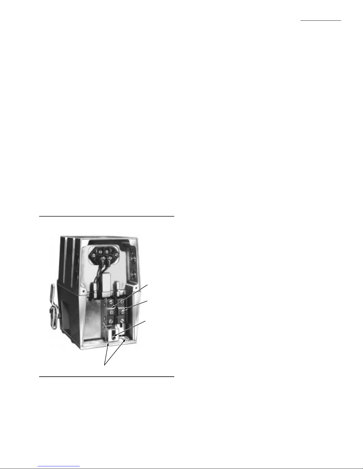
Fig. 2—V4055 Actuator with cover removed.
133568
AUXILIARY
SWITCH
133569
PROOF-OFCLOSURE
SWITCH
ADJUSTING
SCREW FOR
AUXILIARY
SWITCH
EACH SWITCH
SECURED BY TWO
SCREWS FROM
BOTTOM OF BASE.
IF ONLY ONE SWITCH IS
USED, INSTALL BARRIER
IN OPEN POSITION.
M7326
To install the switches, proceed as follows:
1. Remove the actuator faceplate (two screws).
2. Remove the sliver-colored barrier to expose the actua-
tor stem.
3. Insert the auxiliary switch in the position indicated in
Fig. 2. Fasten with two screws through the actuator base.
TO REPLACE A V4034 ACTUATOR ON A V5034
VALVE
IMPORTANT: When replacing a standard (26 sec) V4034
actuator on a V5034 Valve, check the main burner
flame-establishing period (MFEP) of the burner primary safety control. If the MFEP is 10 sec, you must
use a fast-opening (13 sec) V4055 Actuator on the
older V5034 Valve.
The initial action of the V4055 Actuator does not
immediately open the V5034 Valve because of a difference in stroke length. The pilot may be shut off before
the main burner flame is established. The fast-opening
V4055 Actuator will open the V5034 Valve fast enough
to establish the main burner flame within the ten
second flame-establishing period.
If it is desirable to maintain the slower opening
characteristic of the standard V4034 Actuator, both
the V4034 Actuator and V5034 Valve should be replaced. Use a standard V4055 Actuator on a V5055
Valve.
Select the correct adapter, depending on whether the
V5034 has a long or short stem (Fig. 3). Fasten the adapter
to the V5034 Valve bonnet, and then mount the actuator on
the adapter. Follow the instructions for mounting the actuator on the valve.
If the V4034 being replaced is equipped with a heater,
there will be a low limit control connected in series with the
V4034 power supply to prevent actuator operation below
25°F [-4°C]. There will also be a constant source of the line
voltage power to the heater and its control thermostat.
5 60-2309—8
V4055A,B,D,E
INSTALLATION
Fig. 3—Adapters permit use of V4055 Actuator
with V5034 Valve.
USE NO. 133534A
ADAPTER WITH
USE NO. 133533A
ADAPTER WITH
SHORT STEM V5034
LONG STEM V5034
M7325
The V4055 is rated for ambient temperature down to -
40°F [-40°C] for 60 Hz models, or -10°F [-23°] for 50 Hz
and 50/60 Hz models, and does not require a heater. Remove all the wiring associated with the heater. Disconnect
the power supply for the heater at its source and remove the
wires. See Fig. 4.
Fig. 4—Remove heater circuits, if installed,
when replacing V4034 Actuator.
BLACK
WHITE
HEATER
THERMOSTAT
HEATER
LOW
LIMIT
HEATER
CIRCUIT
REMOVE HEATER CIRCUIT
COMPLETELY AND
REMOVE LOW LIMIT
V4034
1
M7333
L1
(HOT)
L2
TO MAIN
VALVE TERMINAL
ON BURNER CONTROL
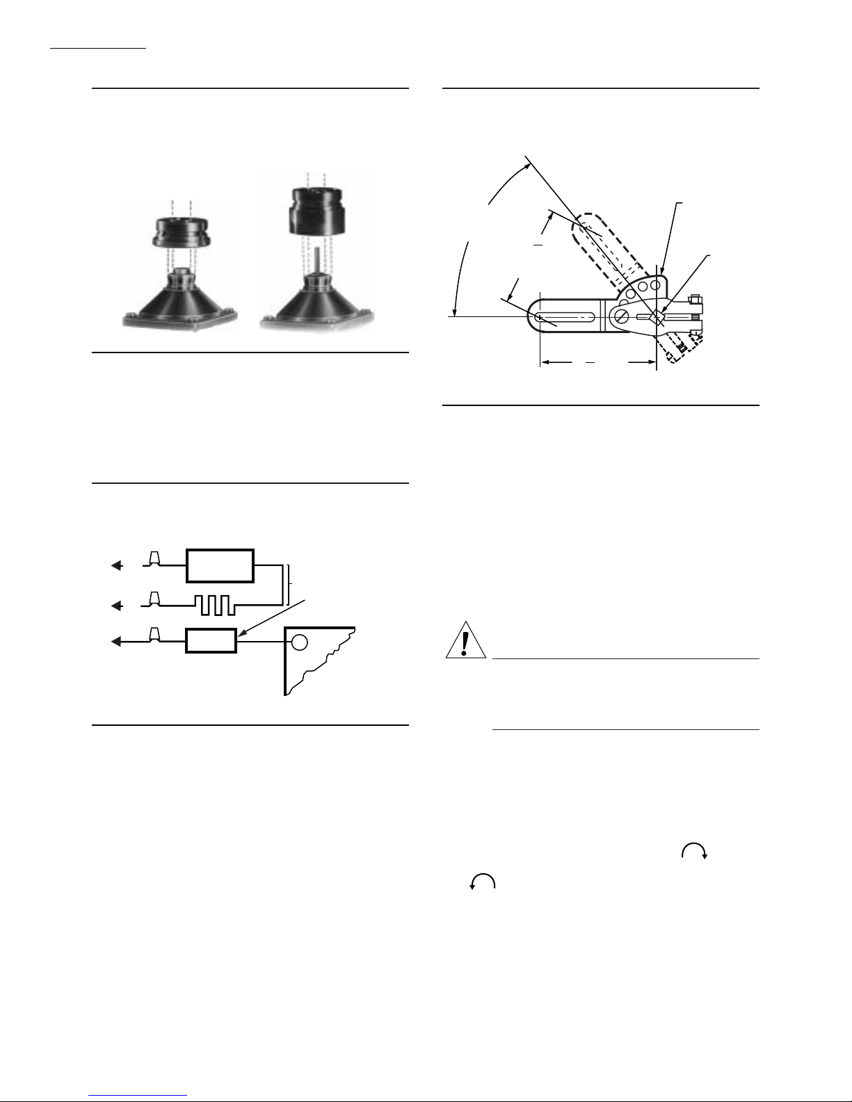
Fig. 5—7616BR Damper Crank Arm may be
attached to actuator shaft to drive a damper
when valve is opened.
7616BR
52 DEGREE
ANGULAR
ROTATION
5
2
16
MAXIMUM
TRAVEL
[59]
11
1
16
RADIUS
[68]
DAMPER
ARM
M7322
SHAFT
WIRING
Disconnect power supply before making electrical con-
nections to prevent electrical shock or equipment damage.
Wiring must comply with all applicable electrical codes,
ordinances, and regulations. Wiring to the actuator must be
NEC Class 1.
Connect the power supply to terminals 1 and 2 on the
V4055 terminal strip. Refer to Fig. 6 for auxiliary switch
connections. For typical system hookups, refer to Fig. 7
and to instructions packed with device used to control
valve.
When all wiring connections are complete, replace the
actuator faceplate.
CAUTION
Label all wires prior to disconnection when servicing values.Wiring errors can cause improper and
dangerous operation.
Verify proper operation after servicing.
MOUNT AND ADJUST 7616BR DAMPER CRANK
ARM (IF USED)
IMPORTANT: When a damper crank arm is used with a
NEMA 4 actuator that is exposed to ice or sleet, a
suitable shield must be installed to prevent ice or sleet
buildup.
Follow installation and adjustment directions included
with damper crank arm. Maximum pushrod travel is 2-5/16
in. [58.7 mm] through a stroke of 52 degrees. See Fig. 5.
60-2309—8 6
NOTE: Pipe sealant is required on the conduit threads of
actuators with NEMA 4 enclosures.
ADJUST THE AUXILIARY SWITCH (IF USED)
The auxiliary switch is adjustable throughout the stroke
of the actuator. With the switch installed in the actuator,
turn the adjusting screw (Fig. 2) clockwise to cause
the switch to operate earlier in the stroke or counterclockwise to cause the switch to operate later in the stroke.
NOTE: The proof-of-closure switch is not adjustable.
 Loading...