

Honeywell V804B, V404B Installation Manual
Honeywell
V400 AND V800
COMBINATION GAS CONTROLS
APPLICATION
V400 and V800 are used on gas fired standing pilot
appliances with 30 mV thermocouple. These gas controls
include a manual gas valve, safety shutoff, single millivoltage automatic operator, and pressure regulator, pilot gas
filter and flow adjustment, pressure tapping, and thermocouple connector.
V400 is used on 120V systems. V800 is used on 24V
systems. Refer to Table 1 for more specifications. Refer to
Table 2 for available gas capacities.
V800 gas controls are available with 1/4 x 1/4 inch or 3/
16 x 1/4 inch energy cut-off (ECO) quick-connects. With the
connector, an ECO high limit can be connected into the
power circuit. When the temperature at the ECO exceeds
the high limit, a switch opens and de-energizes the power
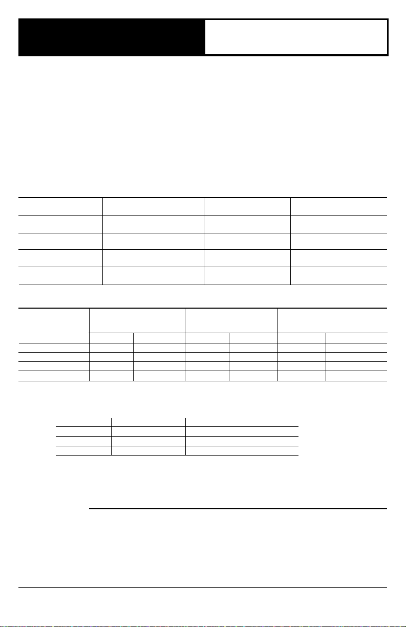
TABLE 1—MODEL SPECIFICATIONS.
MODEL NUMBER AMBIENT PRESSURE PRESSURE
SUFFIX LETTER TEMPERATURE RANGE REGULATOR TYPE REGULATOR MODEL
A32° F to 175° F Standard-Opening V5306A
C32° F to 175° F Step-Opening V5307A
M-40° F to 175° F Standard-Opening V5306B
P-40° F to 175° F Step-Opening V5307B
PIPE SIZE CAPACITY
(INLET x 1 INCH WCPD CAPACITY CAPACITY
OUTLET) ft
1/2" x 3/8" 110 3.1 110 3.1 11 0.3
1/2" x 1/2" 225 6.4 225 6.4 23 0.7
1/2" x 3/4" 250 7.1 290 8.2 23 0.7
3/4" x 3/4" 335 9.5 425 12.0 34 1.0
a
Capacity is based on 1000 Btu/ft3, 0.64 specific gravity natural gas at 1 inch wc pressure drop [37.3 MJ/m3, 0.64 specific
gravity natural gas at 0.25 kPa pressure drop]. Use conversion factors to convert to other gases.
[0° C to 79° C]
[0° C to 79° C]
[-40° C to 79° C]
[-40° C to 79° C]
TABLE 2—GAS CONTROL CAPACITIES.
GAS CONTROL MAXIMUM MINIMUM
3
/hr m3/hr ft3/hr m3/hr ft3/hr m3/hr
a
AT REGULATION REGULATION
unit and shuts off main burner and pilot gas flow. To restart
system, pilot flame must be relit and gas control must be
reset manually.
Power for the gas control and the control system is
provided by a 30 mV thermocouple. We recommend the
Q340 Thermocouple.
Replacement parts:
1. Energy cut off (ECO) connector: 392451-1
2. Pressure Regulators:
Standard opening pressure regulator: V5306A,B.
Step opening pressure regulator: V5307A,B.
3. Valve Operators:
Line Voltage Operator: V404B.
Low Voltage Operator: V804B.
TYPE OF GAS SPECIFIC GRAVITY MULTIPLY LISTED CAPACITY BY:
Manufactured 0.60 0.516
Mixed 0.70 0.765
Propane 1.53 1.62
INSTALLATION
WHEN INSTALLING THIS PRODUCT…
1. Read these instructions carefully. Failure to follow
them could damage the product or cause a hazardous
condition.
2. Check the ratings given in these instructions and on
the product to ensure the product is suitable for your
application.
J.A. Form Number 95-6996—10
Rev. 6-91 ©Honeywell Inc. 1991
3. Ensure installer is a trained, experienced service
technician.
4. After completing installation, use these instructions to
check product operation.
WARNING
FIRE OR EXPLOSION HAZARD
CAN CAUSE PROPERTY DAMAGE, SEVERE INJURY, OR DEATH
Follow these warnings exactly:
1. Disconnect power supply before wiring to prevent
electrical shock or equipment damage.
2. To avoid dangerous accumulation of fuel gas, turn
off gas supply at appliance service valve before
starting installation and perform Gas Leak Test
following installation.
3. Do not bend pilot gas tubing at control or at pilot
burner after compression fitting is tightened. Gas
leakage at the connection may result.
4. Always install sediment trap in gas supply line to
prevent contamination of gas control.
5. Do not force gas control knob. Use only your hand
to turn gas control knob. If the knob will not operate
by hand, the control should be replaced by a
qualified service technician. Force or attempted
repair may result in fire or explosion.
Never apply a jumper across (or short) gas control
coil terminals. This may burn out thermostat heat
anticipator.
These gas controls are shipped with protective seals
over inlet and outlet tappings. Do not remove seals
until ready to connect piping.
Follow the appliance manufacturer’s instructions if available; otherwise, use the instructions provided below as a
guide.
CHOOSE LOCATION
Do not locate the combination gas control where it may
be affected by steam cleaning, high humidity, dripping
water, corrosive chemicals, dust or grease accumulation,
or excessive heat. To ensure proper operation, follow these
guidelines.
• Locate in a well ventilated area.
• Mount high enough above the cabinet bottom to
avoid exposure to flooding or splashing water.
• Ensure the ambient temperature does not exceed the
ambient temperature ratings for each component.
• Cover gas control if appliance is cleaned with water,
steam, or chemicals or to avoid dust and grease
accumulation.
• Avoid locating where exposure to corrosive chemical
fumes or dripping water are likely.
Mount combination gas control in the appliance vestibule on the gas manifold. In replacement applications,
mount gas control in the same location as the old control.
INSTALL PIPING TO CONTROL
All piping must comply with local codes and ordinances
or with National Fuel Gas Code (ANSI Z223.1 NFPA No.
54), whichever applies. Tubing installation must comply
with approved standards and practices.
1. Use new, properly reamed pipe free from chips. If
tubing is used, make sure ends are square, deburred, and
clean. All tubing bends must be smooth and without deformation.
2. Run pipe or tubing to the control. If tubing is used,
obtain a tube-to-pipe coupling to connect tubing to the
CAUTION
IMPORTANT
control.
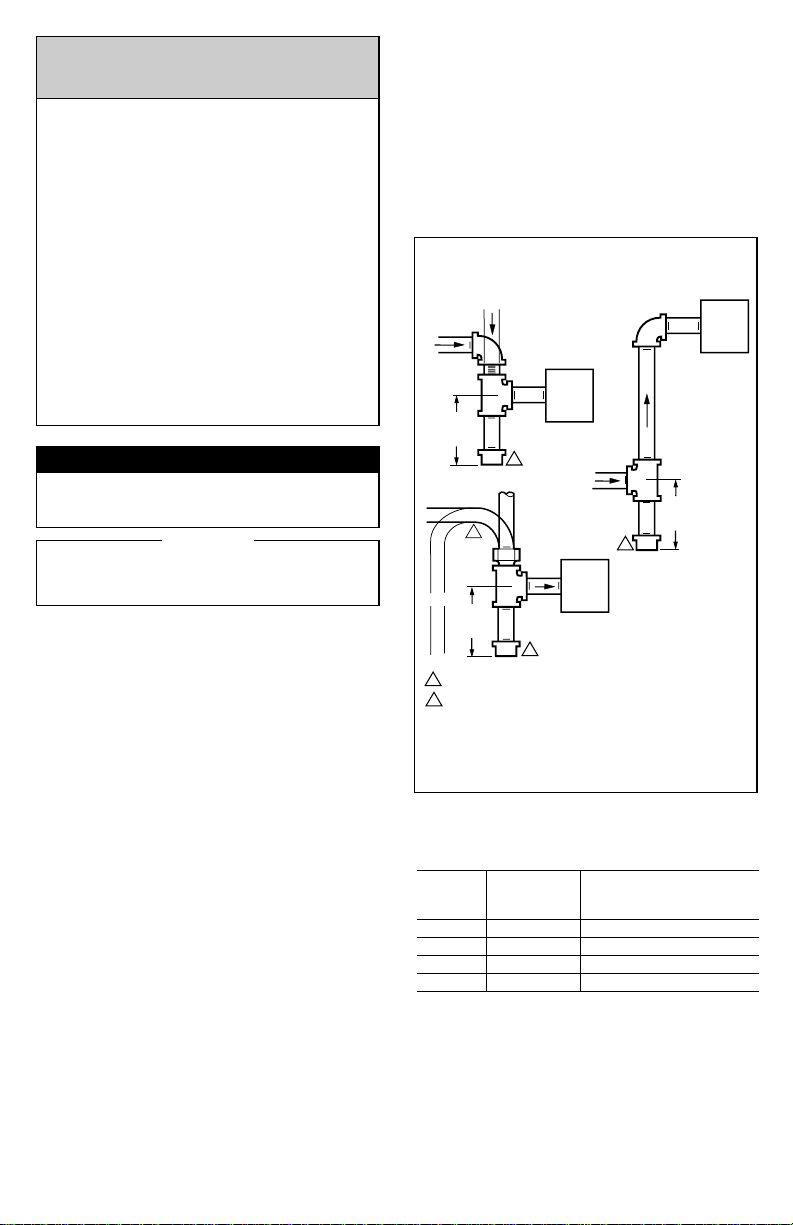
3. Install sediment trap in gas supply line. Refer to Fig. 1.
INSTALL CONTROL
1. This control can be mounted 0-90 degrees, in any
direction, from the upright position of the gas control knob,
including vertically.
2. Mount the control so gas flow is in direction of arrow
on bottom of control.
3. Thread pipe the amount shown in Table 3 for insertion
into control. DO NOT THREAD PIPE TOO FAR. Valve
distortion or malfunction may result if pipe is inserted too
deeply.
DROP
3 IN.
PIPED
GAS
SUPPLY
GAS
CONTROL
2
DROP
TUBING
1
GAS
SUPPLY
2
GAS
CONTROL
2
HORIZONTAL
3 IN.
(76 MM)
MINIMUM
HORIZONTAL
RISER
(76 MM)
MINIMUM
ALL BENDS IN METALLIC TUBING SHOULD BE SMOOTH.
1
CAUTION: SHUT OFF THE MAIN GAS SUPPLY BEFORE REMOVING
2
END CAP TO PREVENT GAS FROM FILLING THE WORK AREA. TEST
FOR GAS LEAKAGE WHEN INSTALLATION IS COMPLETE.
RISER
PIPED
GAS
SUPPLY
3 IN.
(76 MM)
MINIMUM
GAS
CONTROL
M3077
Fig. 1—Install sediment trap.
TABLE 3—NPT PIPE THREAD LENGTH (IN.).
PIPE THREAD CAN BE INSERTED
SIZE LENGTH INTO CONTROL
OVERALL MAXIMUM DEPTH PIPE
3/8 9/16 3/8
1/2 3/4 1/2
3/4 13/16 3/4
19/16 1
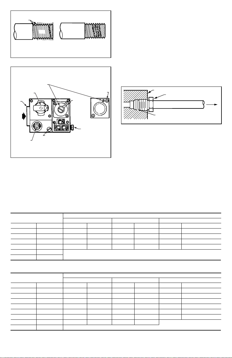
4. Apply moderate amount of good quality pipe compound to adapter, leaving two end threads bare. Refer to
Fig. 2. (On LP gas installations, use compound resistant to
LP gas.) Do not use Teflon tape.
5. Remove seals over control inlet and outlet, if necessary.
6. Connect pipe to control inlet and outlet. To tighten inlet
and outlet connections, use wrench on projecting wrench
boss. Refer to Figs. 3 and 4.
2
3. Unscrew brass compression fitting from pilot gas
TWO IMPERFECT
THREADS
THREAD PIPE THE AMOUNT
SHOWN IN TABLE FOR
INSERTION INTO GAS CONTROL
GAS CONTROL
PIPE
APPLY A MODERATE AMOUNT OF
PIPE COMPOUND TO PIPE ONLY
(LEAVE TWO END THREADS BARE).
M3075B
Fig. 2—Use moderate amount of pipe compound.
PRESSURE REGULATOR
ADJUSTMENT
(BENEATH COVER SCREW)
MANUAL GAS
CONTROL KNOB
WRENCH
BOSS
PILOTSTAT
POWER UNIT
GAS
INLET
OFF
INLET
PILOT
STANDARD
PRESSURE
ON
PILOT FLOW ADJ. SCREW
(BENEATH COVER SCREW)
REGULATOR
("A" MODEL)
STEP OPENING
REGULATOR ("C" MODEL)
INSTALL
LONG
SCREW IN
OUTSIDE
CORNER
PILOT GAS OUTLET.
PRESSURE TAPPING
DIRECTLY BENEATH
M17845
Fig. 3—Top view of standard capacity gas control.
CONNECT PILOT GAS TUBING
1. Cut tubing to desired length and bend as necessary
for routing to pilot burner. Do not make sharp bends or
deform tubing. Do not bend tubing at control after compression nut has been tightened, as this may result in gas
leakage at connection.
2. Square off and remove burrs from end of tubing.
outlet. Refer to Fig. 4. Slip fitting over tubing and slide out
of way.
NOTE: When replacing a control, cut off old compression
fitting and replace with new compression fitting provided
on new combination gas control. Never use old compression fitting as it may not provide a gas-tight seal.
Refer to Fig. 4.
4. Push tubing into pilot gas tapping on outlet end of the
control until it bottoms. While holding tubing all the way in,
slide fitting into place and engage threads. Turn until finger
tight. Then tighten one more turn with wrench. Do not
overtighten.
5. Connect other end of tubing to pilot burner according
to pilot burner manufacturer’s instructions.
GAS CONTROL
TIGHTEN NUT ONE TURN
BEYOND FINGER TIGHT.
FITTING BREAKS OFF AND CLINCHES
TUBING AS NUT IS TIGHTENED.
TO PILOT
BURNER
M3076A
Fig. 4—Always use new compression fitting.
CONNECT THERMOCOUPLE
The thermocouple connection to the power unit or ECO
connector (Fig. 3) is an electrical connection and must be
clean and dry. Never use pipe compound. Tighten only
1/4 turn beyond finger tight to give good electrical
continuity.
CONNECT ECO (Standard-Capacity models only)
If the ECO is provided, the leadwires must be equipped
with insulated 1/4 in. female quick-connect terminals.
Leadwire lengths must not exceed the lengths shown in
Tables 4 and 5. Connect high limit or ECO leadwires to the
two terminals on the thermocouple.
If ECO is not provided, connect a Q313B Thermopile
Generator in place of the thermocouple to act as the highlimit for the system.
TABLE 4—MAXIMUM LENGTH OF SUPPLEMENTARY LIMIT LEADWIRES WHEN USING Q340A THERMOCOUPLE.
THERMOCOUPLE MAXIMUM LEADWIRE LENGTH X 2 (wires)
LENGTH AWG NO. 14 AWG NO. 16 AWG NO. 18
in. m in. m in. m in. m
18 0.5 35 0.9 22 0.6 13 0.3
24 0.6 29 0.7 18 0.5 11 0.3
30 0.8 23 0.6 15 0.4 9 0.2
36 0.9 17 0.4 11 0.3 6 0.2
48 1.2 DO NOT USE.
60 1.5
TABLE 5—MAXIMUM LENGTH OF SUPPLEMENTARY LIMIT LEADWIRE WHEN USING Q309A THERMOCOUPLE.
THERMOCOUPLE MAXIMUM LEADWIRE LENGTH X 2 (wires)
LENGTH AWG NO. 14 AWG NO. 16 AWG NO. 18
in. m in. m in. m in. m
12 0.3 47 1.2 30 0.8 18 0.5
18 0.5 41 1.0 26 0.7 16 0.4
24 0.6 35 0.9 22 0.6 14 0.4
30 0.8 29 0.8 18 0.5 11 0.3
36 0.9 23 0.6 15 0.4 9 0.2
40 1.0 19 0.5 12 0.3 7 0.2
48 1.2 11 0.3 7 0.2
60 1.5 DO NOT USE.
3 95-6996—10
 Loading...