

Page 1

Honeywell
Ultrakey Lite
P/N: 800-00530 Rev. A
User Guide
Page 2

Page 3

Contents
1 About This Document .....................................................................................................1
Overview of Contents ........................................................................................................1
Special Font and Symbols.................................................................................................1
How to Use This Document...............................................................................................1
2 Introduction......................................................................................................................3
Overview............................................................................................................................3
Package Checklist ............................................................................................................. 3
Specifications..................................................................................................................... 4
3 Front Panel, Interfaces and Terminal Box ....................................................................5
Front Panel ........................................................................................................................5
Interfaces ........................................................................................................................... 7
Terminal Box...................................................................................................................... 8
4 System Configuration ...................................................................................................10
Starting Ultrakey Lite .......................................................................................................10
Login ................................................................................................................................ 10
Mode Selection................................................................................................................11
Configurations..................................................................................................................11
Serial Port................................................................................................................... 12
Network....................................................................................................................... 14
Language.................................................................................................................... 16
Back Light ................................................................................................................... 16
Cascade...................................................................................................................... 16
Slider Update.............................................................................................................. 16
Hardware Test ............................................................................................................17
About ..........................................................................................................................17
Honeywell
5 VideoBloX Mode ............................................................................................................18
Overview..........................................................................................................................18
Connection.......................................................................................................................18
System Configuration ......................................................................................................19
Operations .......................................................................................................................20
Numeric Selection Keys ............................................................................................. 20
Mode Operations ........................................................................................................ 20
User Function Keys .................................................................................................... 21
PTZ Control ................................................................................................................21
6 Maxpro Mode.................................................................................................................. 22
Connection.......................................................................................................................22
System Configuration ......................................................................................................24
Setting the keyboard address..................................................................................... 24
Setting the Keyboard Baud Rate................................................................................ 25
Setting the Joystick Speed ......................................................................................... 25
Setting the IP Address................................................................................................ 25
Setting Maxpro Port Address...................................................................................... 25
Setting Maxpro Serial Port Mode ............................................................................... 26
Maxpro Key Code............................................................................................................26
7 Standalone Mode ...........................................................................................................28
Standalone Mode Setup .................................................................................................. 28
Connection.......................................................................................................................28
i
Page 4

Honeywell
Fusion DVR .....................................................................................................................29
Keyboard Setup.......................................................................................................... 29
Operations ..................................................................................................................32
HRHD DVR......................................................................................................................34
Keyboard Setup.......................................................................................................... 34
Operations ..................................................................................................................34
Cascade Control..............................................................................................................36
Connection.................................................................................................................. 36
Cascade Setup ........................................................................................................... 37
PTZ Control (Direct Control)............................................................................................37
Keyboard Setup.......................................................................................................... 37
Camera Selecting ....................................................................................................... 38
Operations ..................................................................................................................38
8 Web System ...................................................................................................................40
Login ................................................................................................................................ 40
Configuration ...................................................................................................................41
System Configuration ................................................................................................. 41
Standalone Configuration ........................................................................................... 41
Maxpro Configuration ................................................................................................. 42
VideoBloX Configuration ............................................................................................43
Serial Port Configuration ............................................................................................44
IP Configuration.......................................................................................................... 44
Upgrade ........................................................................................................................... 45
System Reboot ................................................................................................................46
Change Password ...........................................................................................................47
9 Appendix 1: PCKZ-CAS Keyboard Map.......................................................................48
10 Appendix 2: USB Keyboard Map..................................................................................49
ii
Page 5

1 About This Document
Thank you for purchasing Ultrakey Lite!
This user guide is designed to be a reference tool for mounting or operating the Ultrakey Lite.
Overview of Contents
This document contains the following chapters:
• Chapter 1, About This Document, a brief introduction of “UltraKey Lite User Guide”.
• Chapter 2,
and provides the package checklist.
• Chapter 3,
panel and interfaces of the keyboard.
• Chapter 4,
• Chapter 5,
operation when UltraKey Lite is used with VideoBloX.
• Chapter 6,
when UltraKey Lite is used with Maxpro.
• Chapter 7,
operation when UltraKey Lite is used in Standalone mode.
• Chapter 8,
or reboot the system through Internet Explorer.
• Chapter 9,
UltraKey Lite and PCKZ-CAS keyboard.
• Chapter 10,
Lite and general USB keyboard.
Introduction, introduces the main features and specifications of UltraKey Lite,
Front Panel, Interfaces and Terminal Box, describes all parts of the front
System Configuration, provides detailed system configurations.
VideoBloX Mode, describes the connection, system configuration and
Maxpro Mode, describes the connection, system configuration and operation
Standalone Mode, describes the connection, system configuration and
Web System, describes how to configure UltraKey Lite, upgrade its software
Appendix 1: PCKZ-CAS Keyboard Map, lists the key value map between
Appendix 2: USB Keyboard Map, lists the key value map between UltraKey
Honeywell
Special Font and Symbols
Italic
Bold
Note
Indicates emphasis, reference or first-time defined concepts and items.
Indicates it is a button, tab or menu item.
Alert the user to the presence of important operating and maintenance (servicing)
instruction in the literature accompanying the product.
How to Use This Document
• Pictures in the manual are for reference only, so please see the actual items.
• The products will be updated and the information shall not be distributed.
1
Page 6

About This Document
• Please read the book before operation and keep it properly for future use.
• The manual has been reviewed and the accuracy is guaranteed. If there is any
uncertainty or controversy, please refer to the final explanation of Honeywell. Honeywell
does not take any responsibility for any consequences caused by misunderstanding of
the manual or improper operations.
2
Page 7

2 Introduction
Overview
Ultrakey Lite is a remote control keyboard for Maxpro, VideoBloX, PTZ and DVR.
It can be used in three modes: Maxpro mode, VideoBloX mode and Standalone Mode (DVR
and PTZ).
Ultrakey Lite is compatible with the following products:
• VideoBloX
• Maxpro-Net
• DVR: HRHD, Fusion
• PTZ that support Diamond, Pelco P, Pelco D and VCL protocols
Honeywell
Package Checklist
No. Part Name Quantity
1 Ultrakey Lite 1
2 Ultrakey Lite User Guide 1
3 Power Adapter,100-240VAC,12VDC,50-60HZ,1A,12W 1
4 Connector Adapter, RJ45 to DB9M, for RS422 1
5 Connector Adapter, RJ45 to DB9F, for RS232 2
6 RJ45 network cable, 2M 2
7 RJ45 Cross-over Ethernet Cable, 2M, Blue 1
8 RJ11 4X6 Flat ribbon Cable, 2M 1
9 Function Key Label, Blank 1
10 Termination-Box 1
3
Page 8

Introduction
Specifications
Parameter Value
Power Requirements 10.8 to 13.2 VDC @ 1 Ampere (A) or POE (48VDC, Class 3)
Connector Types
1×Ethernet (10Base-T, 100Base-TX) RJ45 With LED
1×RS232/422/485 RJ45 With LED
Type: STN, Positive Image
LCD
USB
Battery
Compliance EN55022 for radiated and conducted emissions
Mechanical
Backlight: Blue-White
Characters: 122×32 Dots
Type: A
Version: USB1.1 (For USB PC Keyboard)
Type: CR2032
Voltage: 3V
Dimensions: 408mm (L) × 215 mm (W) × 105mm (H)
Gross Weight: 3.2 kg
Cover material: ABS+PC (cool gray)
Operating Temperature: -10 to +55 deg C
Environment
4
Storage Temperature: -40 to +75 deg C
Humidity: 0 to 95% RH (non-condensing)
Page 9
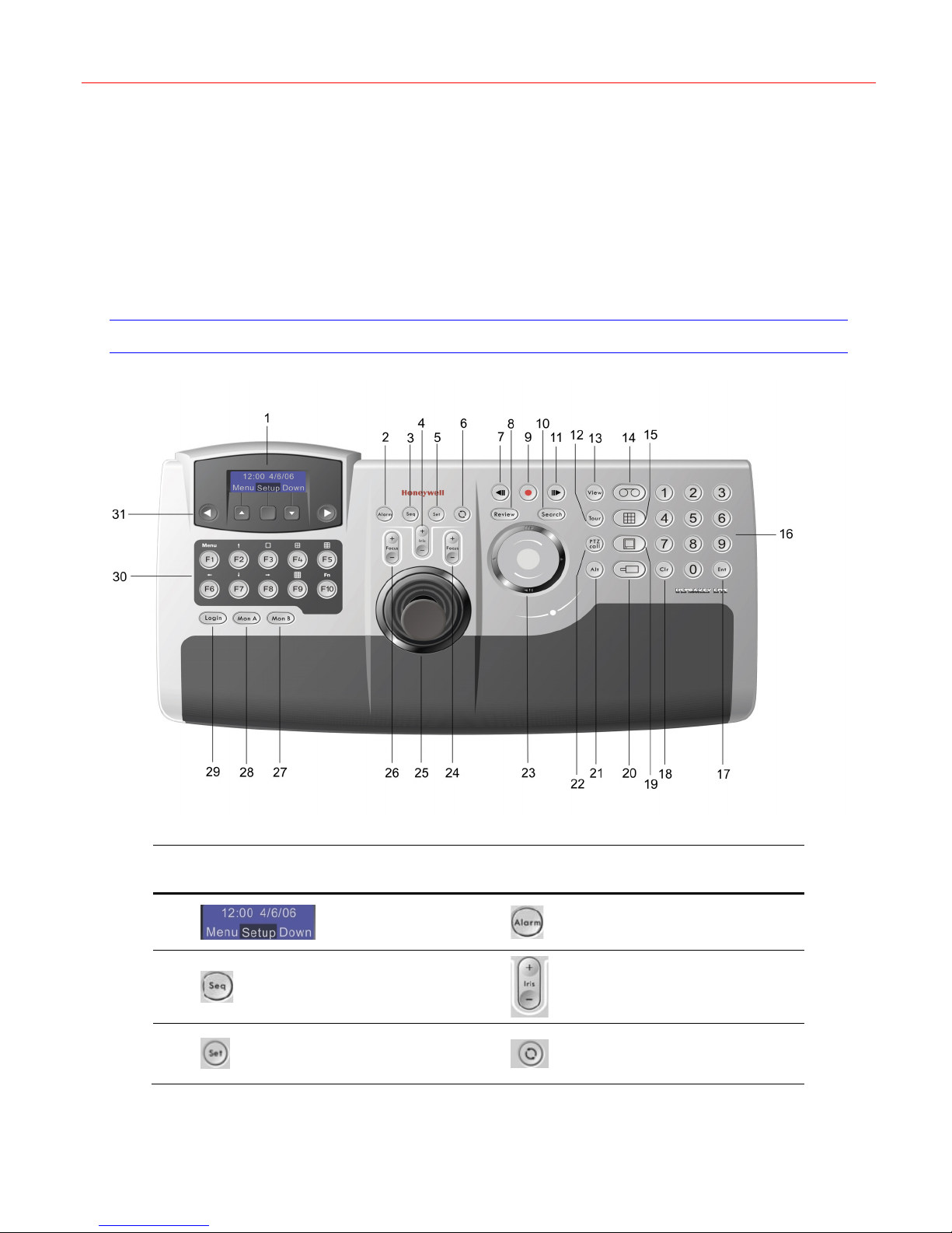
3 Front Panel, Interfaces and Terminal Box
This chapter provides the names and detailed information of all buttons, function keys,
interfaces and terminal box on the Ultrakey Lite.
Front Panel
Honeywell
No. Icon Description No Icon Description
1
3
5
LCD
Seq
Set
2
4
6
Alarm
Iris
Recycle
5
Page 10
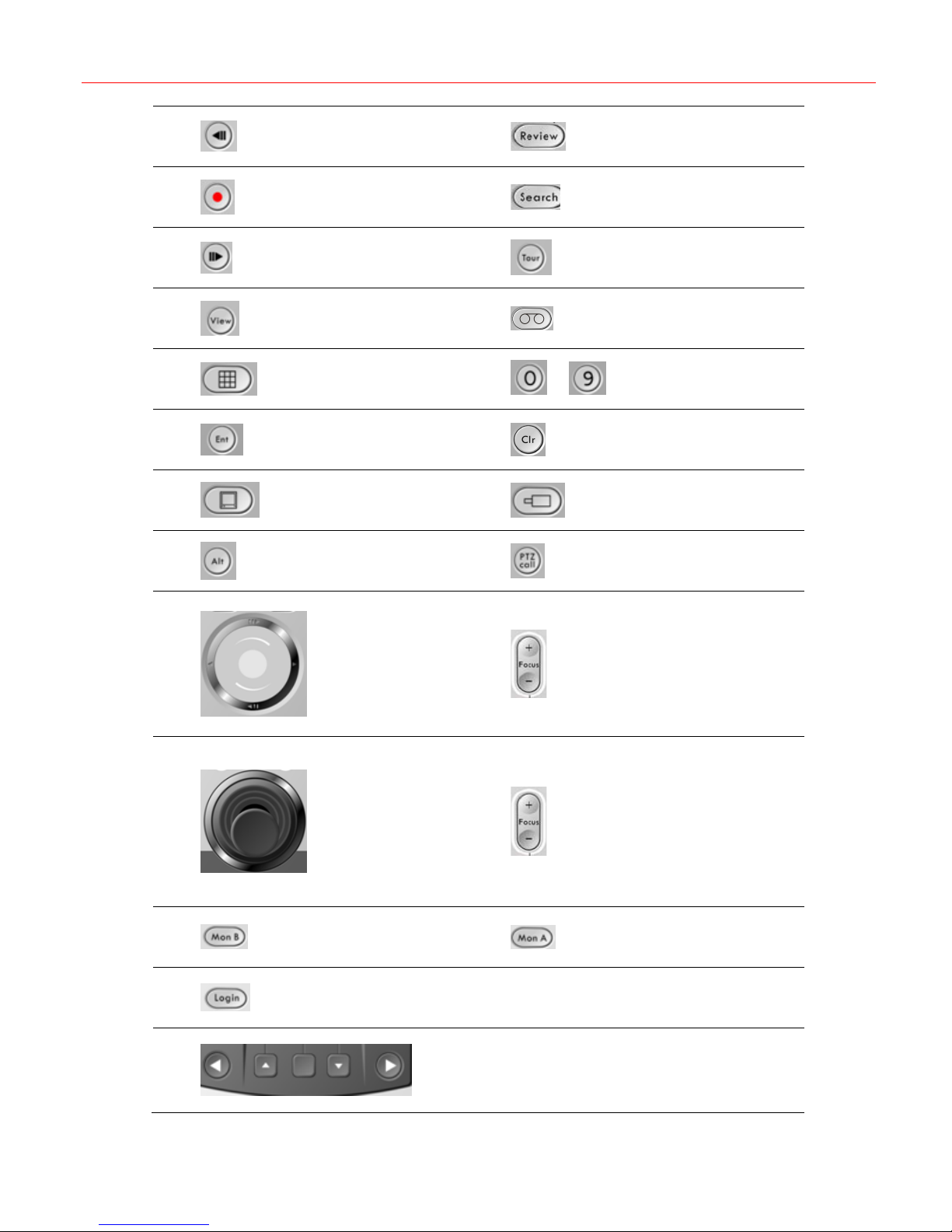
Front Panel, Interfaces and Terminal Box
7
9
11
13
15
17
19
21
Backward
Stop
Forward
View
Split
Ent
Monitor
Alt
8
10
12
14
16
18
20
22
~
Review
Search
Tour
DVR
Number keys
Clr
Camera
PTZ call
23
25
27
29
31
Slider
Slider_Left
Slider_Right
Slider_Up
Slider_Down
Joystick
MonB
Login
24
26
28
30
Key_Left, Key_Up, Select, Key_Down, Key_Right
F1 F2 F3 F4
F5 F6 F7 F8
F9 F10
Focus
Focus
MonA
F1~F10
6
Page 11
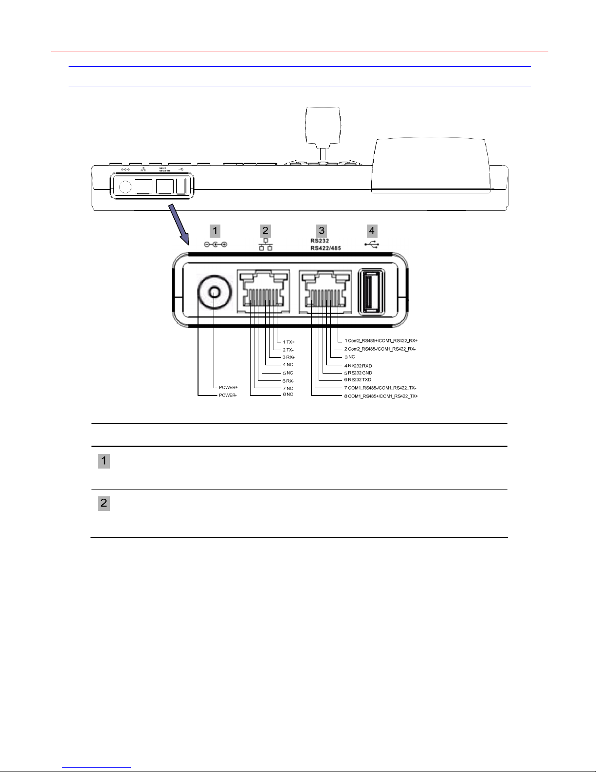
Interfaces
Honeywell
Name Description
DC Power Jack
Ethernet Port
DC Power Jack supports 12V (±10%) DC/1A power input. (Apply the provided
power adapter. When plugging the power adapter plug, please rotate it to lock
the plug.)
10/100M Ethernet (POE input)
Note: For using POE as the power input, it is not recommended to connect the
POE network with an outside plant.
7
Page 12
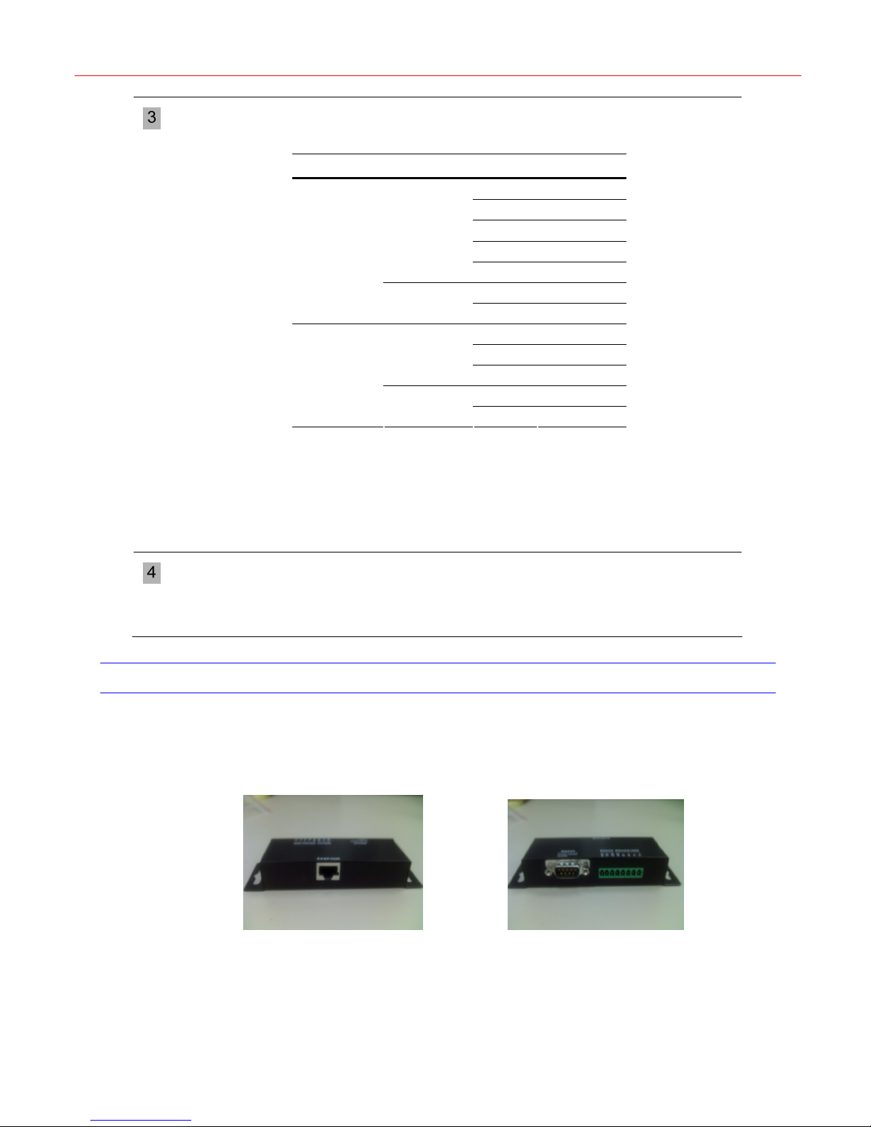
Front Panel, Interfaces and Terminal Box
Serial Port
RS232, RS485 and RS422
Settings of serial ports can be configured in related menu items of the system.
Serial Port Type Pin Signal
1 Rx+
2 Rx-
RS422
COM1
RS485
RS232
COM2
RS485
Note:
COM1 and COM2 are respectively corresponding to ports on the LCD menu.
For configuration of Com1 and Com2, refer to “
that COM1_RS422 and COM2_RS485 cannot be used at the same time.
It is recommended to add an isolated protective device when using
RS485/RS422 for outside plant.
5 GND
7 Tx-
8 Tx+
7 T/R-
8 T/R+
4 RXD
5 GND
6 TXD
1 T/R+
2 T/R-
Serial Port” on page 12. Note
USB Port
Terminal Box
USB Port should be used to connect a QWERTY USB keyboard and the
following USB keyboards are recommended:
Logitech Y-UR83 (Logitech Classic New Touch Keyboard 200 USB),
Y-BP62a and Dell L110
Ultrakey Lite can be connected with other devices by using the Terminal Box. Ultrakey Lite
Serial Port (RJ45) can be connected with Terminal Box’s Back (RJ45) by using a network
cable.
Terminal Box Back Terminal Box Front
The terminal box has a DB9 (Male) for RS232 and can connect with Fusion DVR by DB9 or
HRXD by two Connector Adapters (for RS232) and a network cable. The terminal box also has
an 8 Pin terminal plug for easy connect with other devices.
Refer to the following figure for signal definition of the terminal box:
8
Page 13

Honeywell
9
Page 14
System Configuration
4 System Configuration
This chapter describes how to start, login and configure Ultrakey Lite.
Starting Ultrakey Lite
Connect the keyboard with a power adapter (12V (±10%) DC/1A, attached in the package) or a
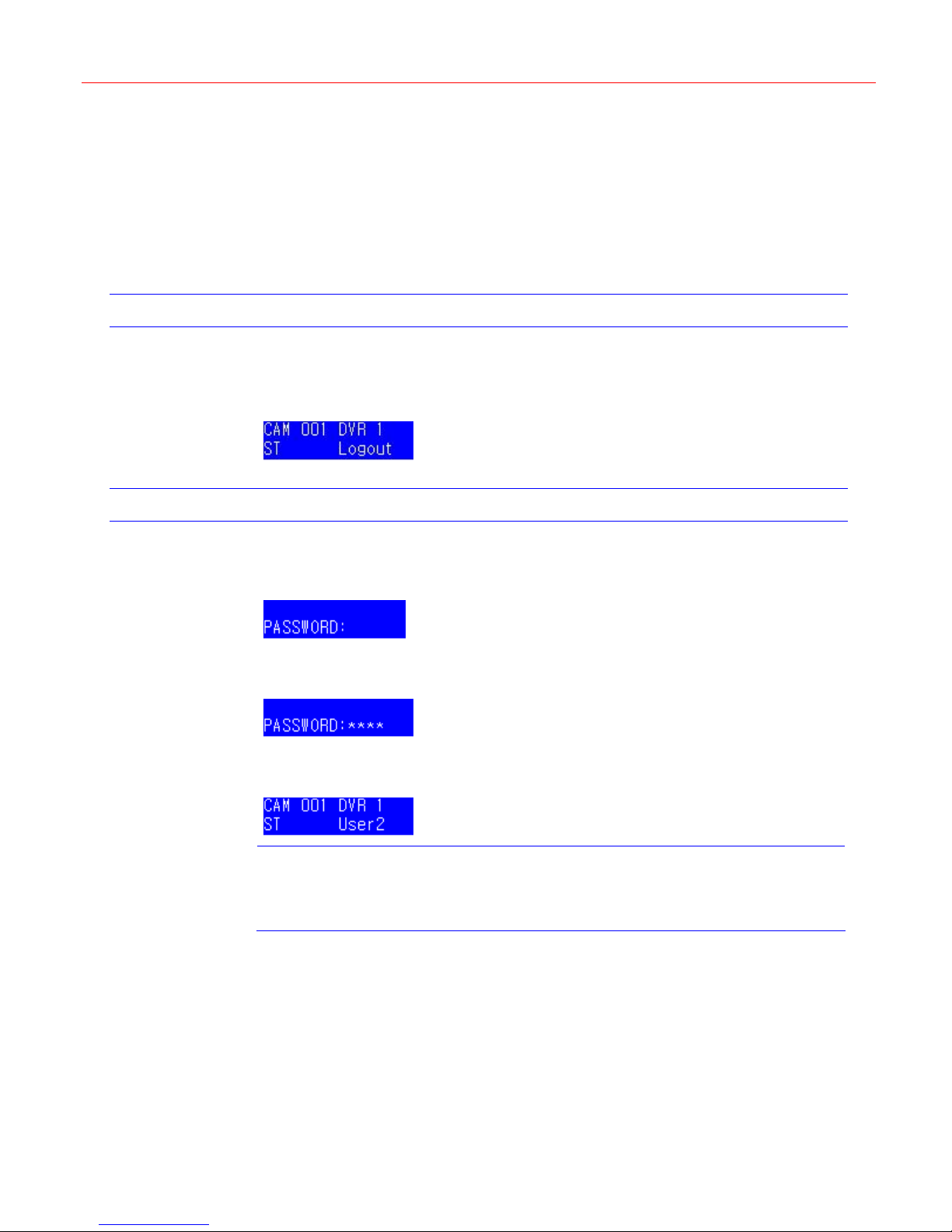
network cable with POE. Then the following figure displays on the LCD.
Figure 4-1 Login
Login
Press Login. Figure 4-2 is displayed on the LCD.
Figure 4-2 Password
Use the number keys to enter the correct password. See
Figure 4-3 Password Input
Press Ent.
Figure 4-4 Login menu
Note
Then you can start configuring the system. Be familiar with the basic operations below:
• To confirm a modification or enter the current menu item, press Ent
Figure 4-4 is displayed.
If the password is invalid, Figure 4-2 will be displayed and it will buzz. You shall
repeat the above steps to log in.
/Slider_Right/Key_Right or move the joystick to the right.
Figure 4-3. (Default password: 3434)
• To cancel an operation or return to the previous level of the menu, press
Slider_Left/Key_Left/Alt+Clr or move the joystick to the left.
• To view or switch between the menu items of the same level, press Slider_Up
/Slider_Down/Key_Up/Key_Down, rotate the slider or move the joystick up/down.
10
Page 15
Mode Selection
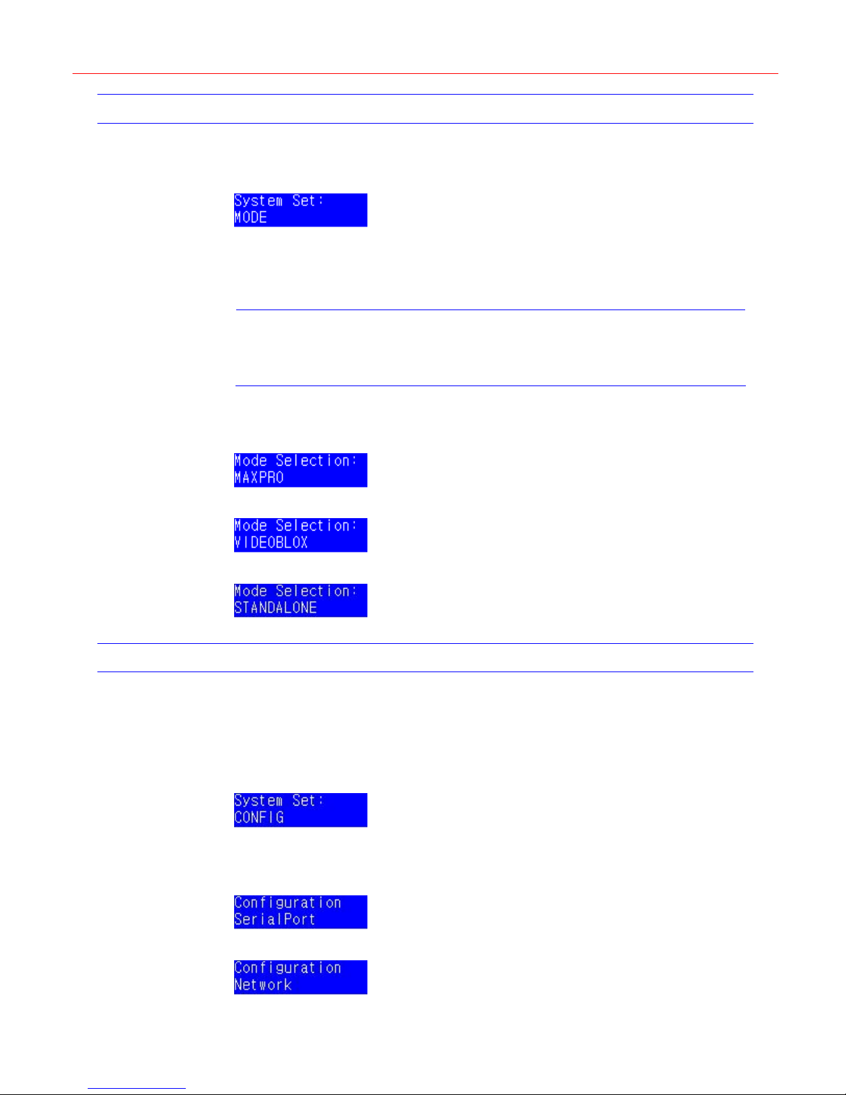
Press Alt+Clr to enter the system setup menu as follows:
Figure 4-5 Mode
There are three mode options: MAXPRO, VIDEOBLOX and STANDALONE. In Standalone
mode, Ultrakey Lite can control DVR and PTZ. Before the keyboard is used, the mode must be
selected.
Press Slider_Right to enter the Mode Selection menu.
Honeywell
In the Mode Selection menu, you can rotate the Slider to switch between the three modes and
press Slider_Right into one mode or press Slider_Left leave the Mode Selection menu.
Figure 4-6 Mode – MAXPRO
Figure 4-7 Mode – VIDEOBLOX
Figure 4-8 Mode – STANDALONE
Configurations
System Configuration is used to set the system parameters. There are eight parameters:
Serial Port, Network, Language, Back Light, Bridge Linkage, Slider Update, Hardware Test
and About.
In
Figure 4-5, rotate the slider until the following figure is displayed.
Figure 4-9 system set menu
Note
If Ultrakey Lite is powered on for the first time, the default mode is
standalone.
Press Slider_Right to enter the configuration menu. One of the following figures is displayed.
You can switch between the items by rotating the slider.
Figure 4-10 System Configuration – Serial Port
Figure 4-11 System Configuration – Network
11
Page 16

System Configuration
Figure 4-12 System Configuration – Language
Figure 4-13 System Configuration – Back Light
Figure 4-14 System Configuration – Bridge Linkage
Figure 4-15 System Configuration – Slider Update
Figure 4-16 System Configuration – Hardware Test
Figure 4-17 System Configuration – About
Serial Port
In Figure 4-10, press Slider_Right and the following figure is displayed.
Figure 4-18 Serial Port
Rotate the slider to select a serial port and then press Slider_Right. The data bit, stop bit, type,
parity, baud rate settings of the certain serial port will display as follows:
Figure 4-19 Serial Port – Type
Figure 4-20 Serial Port – Parity
Figure 4-21 Serial Port – Baud Rate
Figure 4-22 Serial Port – Data Bit
Figure 4-23 Serial Port – Stop Bit
The above menu items can be rotating the slider to display.
12
Page 17
Honeywell
Selecting the type
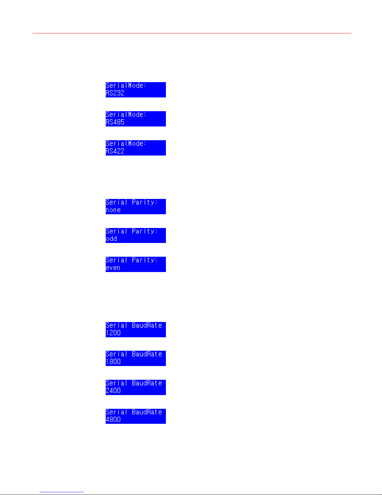
In Figure 4-19, press Slider_Right. There are three options of the serial port type: RS232,
RS485 and RS422. Select one of them by rotate the slider and press Slider_Right.
Figure 4-24 Type – RS232
Figure 4-25 Type – RS485
Figure 4-26 Type – RS422
Setting the parity
In Figure 4-20, press Slider_Right. There are three parity options: None, Odd and Even.
Select one of them by rotate the slider and press Slider_Right to complete the configuration.
Figure 4-27 Parity – None
Figure 4-28 Parity – Odd
Figure 4-29 Parity – Even
Setting the baud rate
In Figure 4-21, press Slider_Right. There are six options: 1200, 1800, 2400, 4800, 9600 and
19200. (From
Slider_Right to complete the configuration.
Figure 4-30 Baud Rate – 1200
Figure 4-31 Baud Rate – 1800
Figure 4-32 Baud Rate – 2400
Figure 4-33 Baud Rate – 4800
Figure 4-30 to Figure 4-35) Select a proper one by rotate the slider and press
13
Page 18
System Configuration
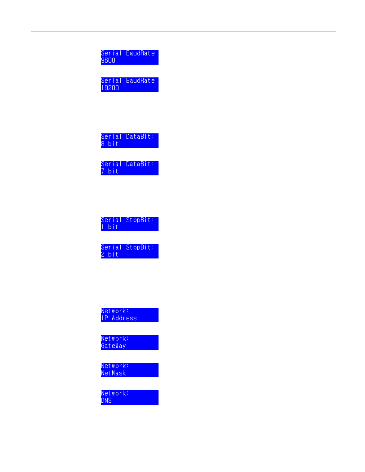
Figure 4-34 Baud Rate – 9600
Figure 4-35 Baud Rate – 19200
Setting the data bit
In Figure 4-22, press Slider_Right. There are two options: 8 bit and 7 bit. Select the proper
data bit by rotate the slider and press Slider_Right to complete the configuration.
Figure 4-36 Data Bit – 8 bit
Figure 4-37 Data Bit – 7 bit
Setting the stop bit
In Figure 4-23, press Slider_Right. There are two options: 1 bit and 2 bit. Select the proper
stop bit by rotate the slider and press Slider_Right to complete the configuration.
Figure 4-38 Stop Bit – 1 bit
Network
Figure 4-39 2 Stop Bit – 2 bit
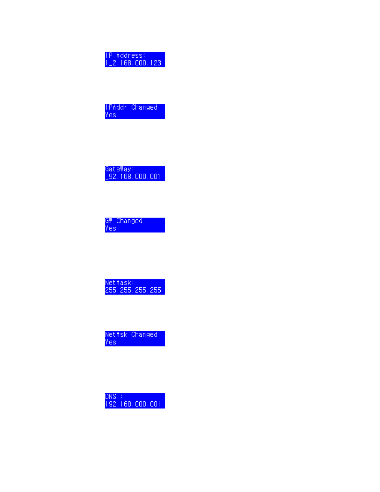
In Figure 4-11, press Slider_Right. You can configure IP address, Gateway, Net mask and
DNS by rotate the slider. (From
Figure 4-40 Network – IP Address
Figure 4-41 Network – Gateway
Figure 4-42 Network – Netmask
Figure 4-43 Network – DNS
Figure 4-40 to Figure 4-42)
Setting the IP address
In Figure 4-40, press Slider_Right and the following figure is displayed.
14
Page 19
Honeywell
Figure 4-44 IP address menu
Use the number keys to input an appropriate IP address and rotate the slider to move the
cursor. When the correct IP address is entered, press Slider_Right and the following
message is displayed.
Figure 4-45 IP Address Changed
Press Slider_Right to complete the modification.
Setting the gateway
In Figure 4-41, press Slider_Right and the following figure is displayed.
Figure 4-46 Gateway
Use the number keys to set an appropriate Gateway and rotate the slider to move the cursor.
When the correct Gateway is input, press Slider_Right and the following message is
displayed.
Figure 4-47 Gateway Changed
Press Slider_Right to complete the modification.
Setting the net mask
In Figure 4-42, press Slider_Right and the following figure is displayed.
Figure 4-48 Net Mask
Use the number keys to set an appropriate net mask and rotate the slider to move the cursor.
When the correct Net Mask is input, press Slider_Right and the following message is
displayed.
Figure 4-49 Net Mask Changed
Press Slider_Right to complete the modification.
Setting the DNS
In Figure 4-43, press Slider_Right and the following figure is displayed.
Figure 4-50 DNS
Use the number keys to set an appropriate DNS and rotate the slider to move the cursor.
When the correct DNS is input, press Slider_Right and the following message is displayed.
15
Page 20
System Configuration
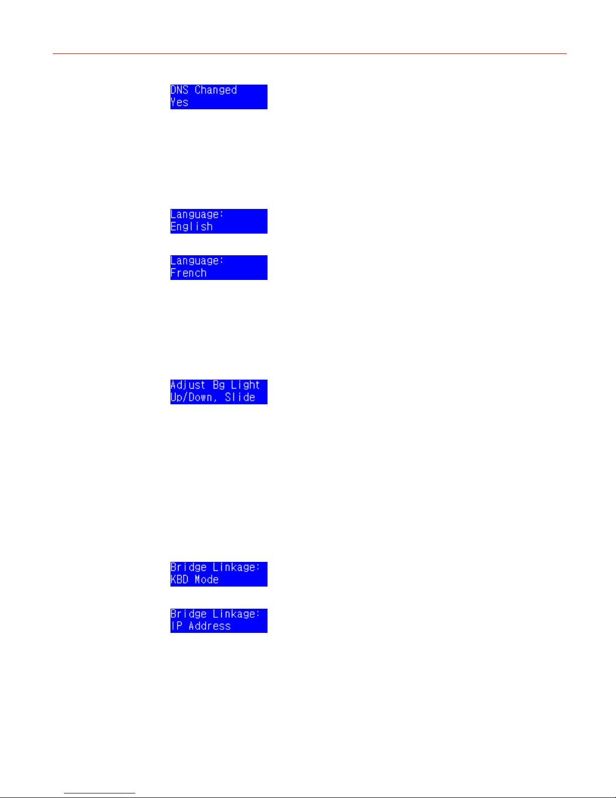
Figure 4-51 DNS Changed
Press Slider_Right to complete the modification.
Language
In Figure 4-12, press Slider_Right to enter the language setup menu. There are two language
options: English and French.
Figure 4-52 Language – English
Figure 4-53 Language – French
Rotate the slider to select a language and then press Slider_Right to complete the
configuration.
Back Light
Cascade
In Figure 4-13, press Slider_Right and the following figure is displayed.
Figure 4-54 Back Light
Rotate the slider to change the brightness of the back light. Then press Slider_Right to
complete the configuration.
In cascade mode, you can set the keyboard status, such as master or slave and the keyboard
IP.
Figure 4-14, press Slider_Right to enter Bridge Linkage menu. There are two menu items:
In
KBD Mode and IP Address. In KBD MODE menu, the master or slave can be set; In IP
Address menu, you can set the IP address which is the same as the Master keyboard’s IP
address.
Figure 4-55 Bridge Linkage – KBD Mode
Figure 4-56 Bridge Linkage – IP Address
Slider Update
To update the firmware of the slider, press Slider_Right in Figure 4-15 and the following figure
is displayed.
16
Page 21
Hardware Test
Honeywell
Figure 4-57 Slider Update
Press Slider_Right to confirm the update.
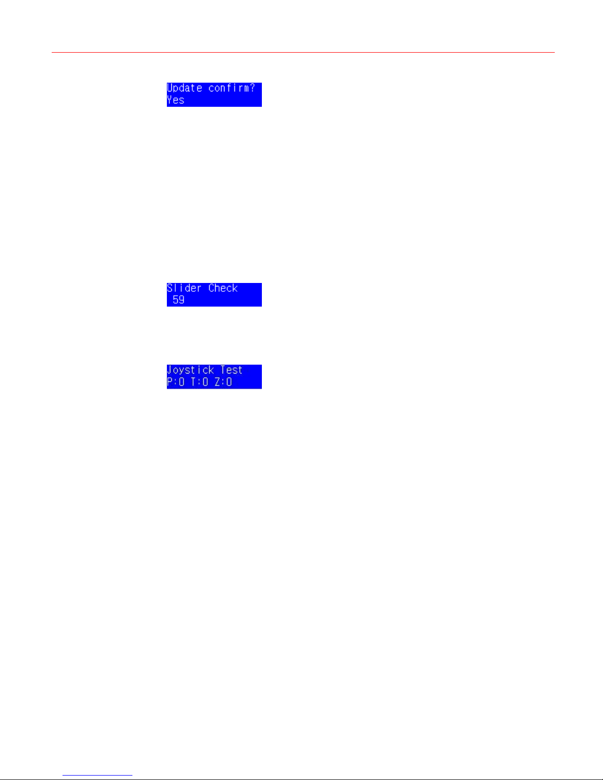
Hardware Test is used to test the components of the keyboard including the keyboard, the
serial ports, the slider and the joystick. Press Slider_Right in Figure 4-16 to enter Hardware
Test menu.
Key test is used to test the key function. In the key test mode, if you press a certain key, the
key value and its state will be displayed on LCD screen.
Serial port test is used to test the serial port of the keyboard.
Slider test is used to test the slider. In the slider test mode, when you rotate the slider, certain
values will be displayed on the LCD screen.
Figure 4-58 Slider Check
Joystick test is used to test the joystick function. In the joystick test mode, when you move the
joystick, values which present different positions of the joystick will be displayed on the LCD
screen.
Figure 4-59 Joystick Test
About
To view the firmware version and other information, press Slider_Right in Figure 4-17 to enter
the “About” menu.
Press Slider_Left to exist the menu.
17
Page 22
VideoBloX Mode
5 VideoBloX Mode
This chapter describes how to connect, configure and operate the Ultrakey Lite when it is used
with VideoBloX.
Overview
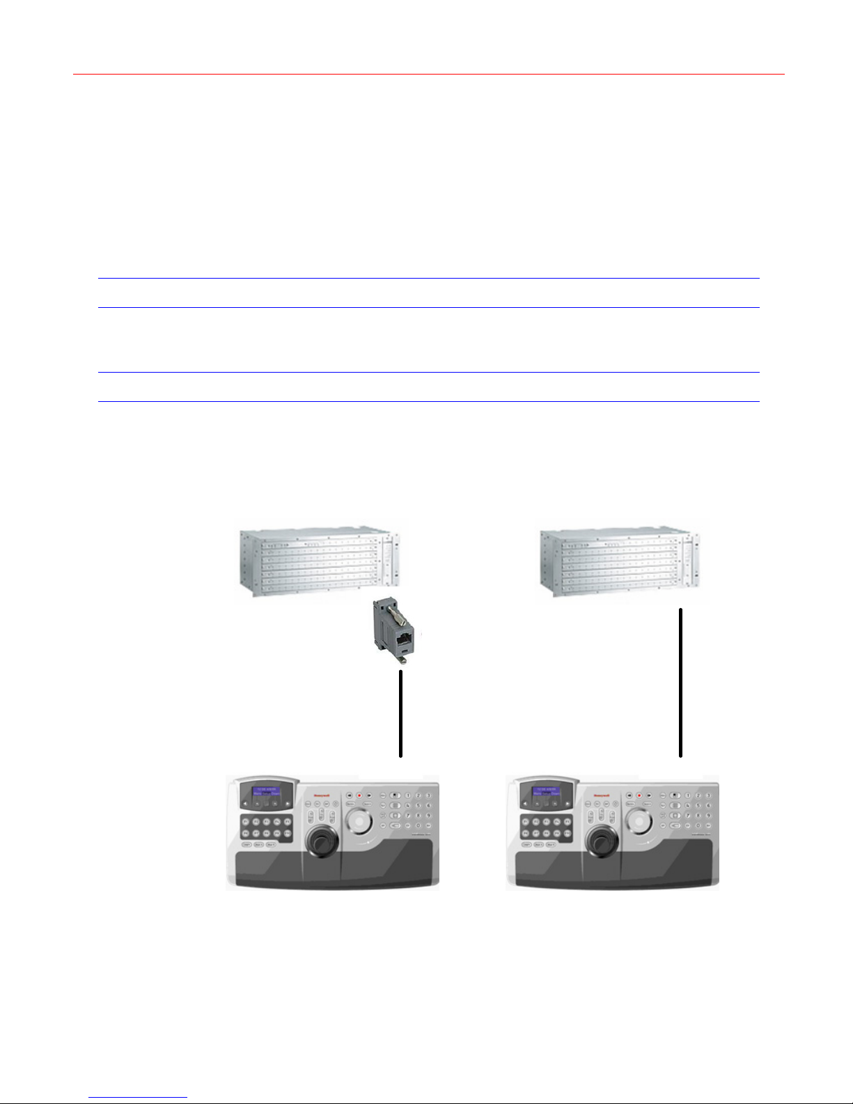
Ultrakey Lite can control the remote VideoBloX via either the serial port or the Ethernet.
Connection
To connect Ultrakey Lite with VideoBloX by the serial port, refer to the following figure:
Figure 5-1 Connecting VideoBloX by Serial Port
VideoBlox (Old)
RJ45 to DB9M
Connector
Network
cable
Serial Port
Ultrakey Lite
To connect Ultrakey Lite with VideoBloX by Ethernet, refer to the following figure:
VideoBlox (New)
Network
cable
Serial Port
Ultrakey Lite
18
Page 23
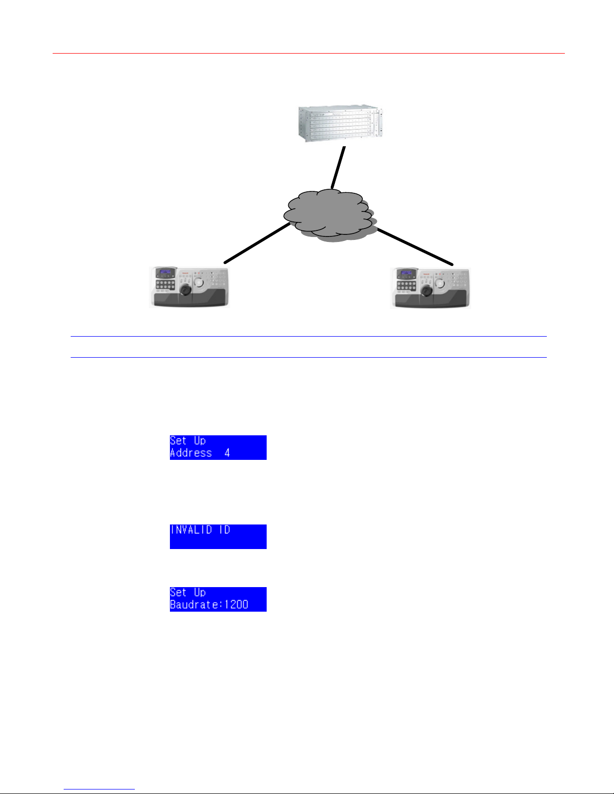
Figure 5-2 Connecting VideoBloX by Ethernet
VideoBloX
NETWORK
TCP\ IP
Network cable Network cable
Honeywell
* Keyboard is running VideoBlox TCP/IP
keyboard Protocol
* Keyboard address range should be 1 to 32
TCP \IP
Ethernet PortEthernet Port
Keyboard 1
System Configuration
Refer to “Mode Selection“ on page 10 to set the mode as VideoBloX.
Figure 4-7, press Select to enter the VideoBloX Setup menu as shown in the following
In
figure:
Figure 5-3 VideoBloX – Address
Press number keys followed by Slider_Right or rotate the slider to set the keyboard address.
Note that the address range should be within 1 ~ 32. If the number input is bigger than 32, the
following figure will display:
Figure 5-4 Invalid Address
Enter a valid address and press Slider_Right. The following figure is displayed:
Figure 5-5 Baud Rate Set Up – 1200
Keyboard 32
There are three options: 1200, 9600 and 19200 bps. Rotate the slider to select the proper
baud rate and then press Slider_Right to complete the configuration.
When
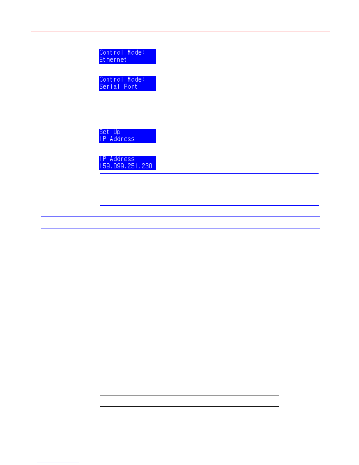
Figure 5-5 shows, press Slider_Right to enter the following menu. There are two
options: Ethernet and Serial Port.
19
Page 24
VideoBloX Mode
Figure 5-6 Control Mode – Ethernet
Figure 5-7 Control Mode – Serial Port
Select one control mode and press Slider_Right to confirm.
Figure 5-8 is displayed. You can configure the IP address of the VideoBloX which is connected
with Ultrakey Lite.
Figure 5-8 Set Up – IP Address
Figure 5-9 IP Address
Note
Operations
When the Ultrakey Lite is powered on, it displays on the LCD the current software revision
number, then its address, baud rate and finally the mode of operation which has been setup.
Numeric Selection Keys
In order to make a selection using the numeric selection keys, type in the required number
using the keys “1” to “9” and “0”. When the required value has been typed in, press Ent. The
function of the “Ent” key varies depending on the current operating mode of the system.
Errors in entering values can be corrected with the “Clr” key.
Once a value has been selected, changing to the next or previous value may readily be
accomplished by using Forward and Backward keys respectively.
Mode Operations
When power on, UltraKey Lite will automatically enter the “Login” mode of operation. In order
to log in to the system, the operator must key in his / her password using the numeric keyboard.
Once the value has been entered, the operator must press Ent. Once the correct password
has been entered the system will be placed into the “Camera” mode of operation.
To prevent unauthorized control of the system the operator must press Login. This will require
the password to be entered again before any system control operation may be executed.
To change the mode, press the required mode function key according to the table below:
If the VideoBloX uses the PCKZ-CAS keyboard, refer to Appendix 1 on page
48 for the key value mapping of Ultrakey Lite and PCKZ-CAS keyboard.
Press… To…
Login/Logout Log in or log out if already logged in.
20
Page 25

Honeywell
Cam Select "Camera" operation mode.
Mon Select "Monitor" operation mode.
Device Select "Device" operation mode.
Seq Select "Sequence" operation mode.
Login Mode
Enter the password on the numeric keypad, then press Ent.
Correct mistakes using the “Clr” Key.
The system is in “Camera” mode by default.
Camera Mode
In “Camera” mode, selecting a value by means of the numeric keypad as described in
“
Numeric Selection Keys” on page 20 causes the selected camera to be switched to the
currently selected monitor. The “||►” and “◄||” keys may be used to step forwards or
backwards through the various cameras in the system.
PTZ unit should be equipped with feedback potentiometers, and then it is possible to store and
recall PTZ preset positions. To store a position, move the PTZ to cover the required scene,
and then press Stop. Enter the required preset number using the numeric keyboard and then
press Ent to store the position. Pressing Clr will abort this operation. To recall a previously
stored position, press DVR. Enter the required preset using the numeric keyboard and the
press Ent to recall the preset. Pressing Clr will abort this operation. To step through
successive preset positions, press DVR and then cycle through positions using the “||►” and
“◄||” keys.
Monitor Mode
In Monitor mode, use the numeric keypad to select the active monitor. To select the next
camera to the currently selected monitor, press Slider_Up; to select the previous one, press
Slider_Down.
Device Mode
In Device mode, use the numeric keypad to select the active device.
The function dependent keys cause the various functions of the Device to be invoked.
Sequence Mode
In Sequence mode, use the numeric keypad to select the active sequence. Press Slider_Left
or Slider_Right to increase or decrease the currently selected sequence. Pressing
“Slider_Up” key will initiate the currently selected sequence. Pressing Slider_Down key will
terminate the sequence.
User Function Keys
In Camera, Monitor, DVR or Sequence mode, pressing F6 ~ F9 will result in sequences being
started by the main controller. Setting up which sequence is to be started is a function of the
CCTV system main controller.
PTZ Control
You can use Joystick to control the PTZ’s pan/tilt and zoom for a right position, and also can
use Slider_Left, Slider_Right, Slider_Up and Slider_Down keys to “nudge” the camera to
provide accurate positioning.
To recall a preset position, press DVR and enter preset number, then press Ent.
To store a preset position, press Stop and enter preset number, then press Ent.
21
Page 26
Maxpro Mode
6 Maxpro Mode
This chapter describes how to connect, configure and operate the Ultrakey Lite when it is used
with Maxpro-Net.
Connection
Ultrakey Lite can control the remote Maxpro via either the serial port or the Ethernet.
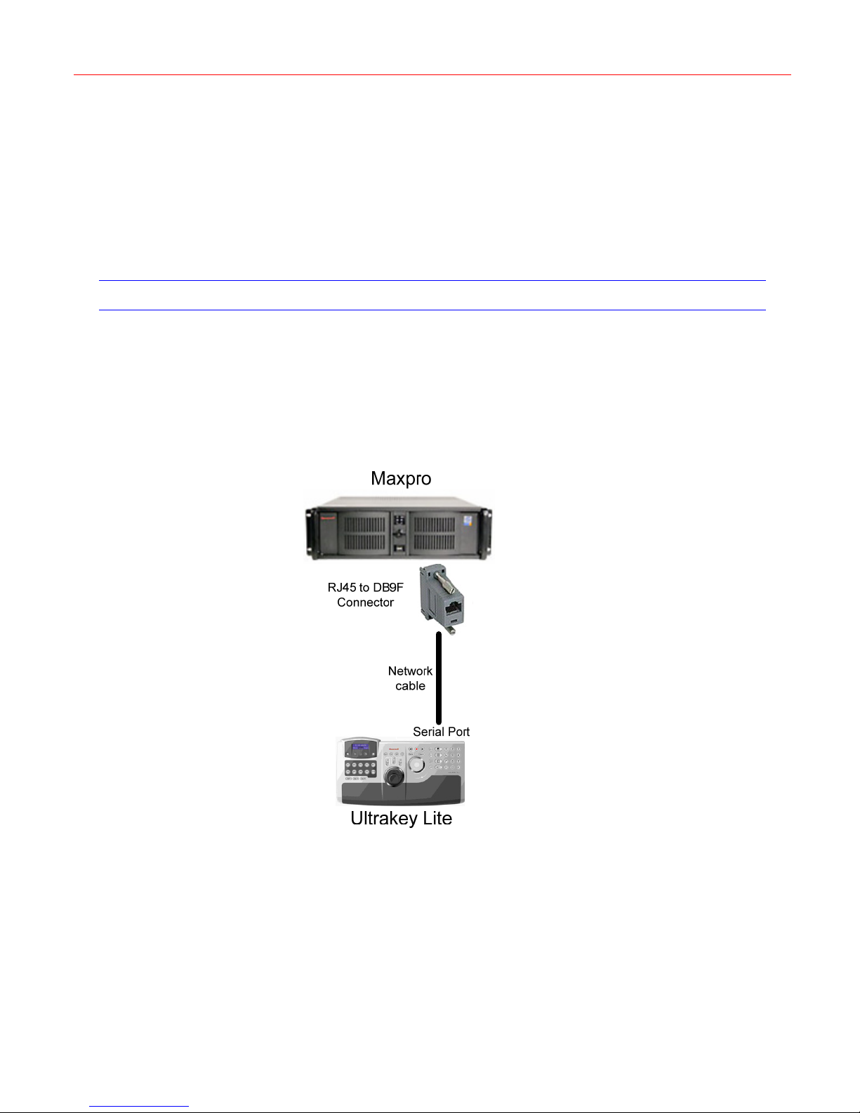
To connect Ultrakey Lite with Maxpro by the serial port, refer to the following figures, normally,
you can select RS232 by menu to connect with Maxpro directly. (
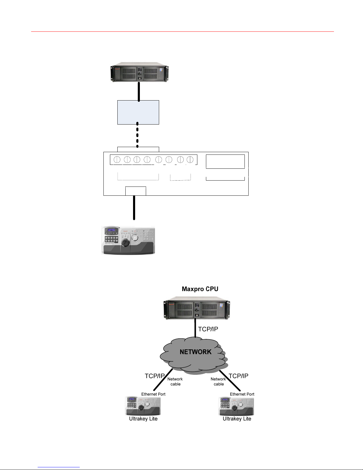
When Ultrakey Lite is remote with Maxpro, you can select RS422 by menu to connect with
Maxpro indirectly. (
Figure 6-1 Connecting Maxpro by Serial Port (RS232 for Ultrakey Lite)
Figure 6-1).
Figure 6-2)
22
Page 27
Honeywell
Figure 6-2 Connecting Maxpro by Serial Port (Remotely, RS422 for Ultrakey Lite)
Maxpro
RS232
RS422 to RS232
converter
RS422
TX+
TX-
RX+
RS422(COM1) RS232(COM2)
RJ45
Network cable
Serial Port(RS422)
GND
RX-
Ultrakey Lite
GND
TXD
RXD
Terminal Box
DB9 Male
2- TXD, 3- T XD, 5- GND
RS232(COM2)
To connect Ultrakey Lite with Maxpro by Ethernet, refer to the following figure:
Figure 6-3 Connecting Maxpro by Ethernet
23
Page 28
Maxpro Mode
System Configuration
Refer to “Mode Selection” on page 10 to set the mode as Maxpro.
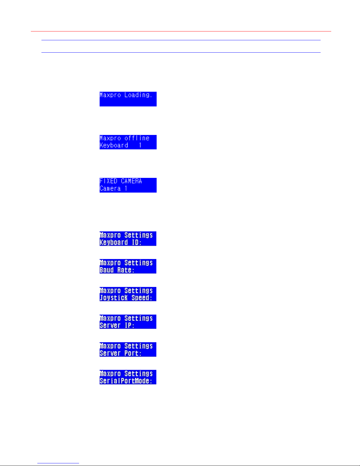
Figure 4-6, press Ent and the following figure is displayed.
In
Figure 6-4 Loading Maxpro
If the keyboard connects the Maxpro server with Ethernet unsuccessfully, the offline menu
displays:
Figure 6-5 Maxpro Offline
If the Maxpro server sends messages to keyboard, the keyboards will display the messages in
the LCD. For example:
Figure 6-6 Fixed Camera
Press Select to enter the Maxpro Settings menu.
One of the following figures is displayed. You can switch between the items by rotating the
slider.
Figure 6-7 Keyboard ID
Figure 6-8 Baud Rate
Figure 6-9 Joystick Speed
Figure 6-10 Server IP
Figure 6-11 Server Port
Figure 6-12 ServerPortMode
Setting the keyboard address
In Figure 4-10, press Slider_Right and the following figure is displayed.
24
Page 29
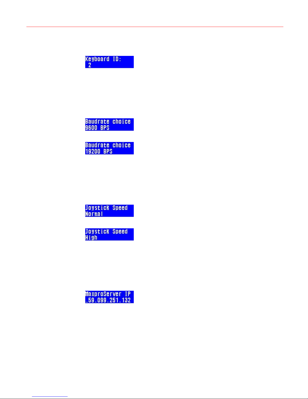
When the keyboard ID menu shows on the LCD screen, rotate the slider to select the keyboard
address, then press Slider_Right to confirm the selection.
Figure 6-13 keyboard ID
Setting the Keyboard Baud Rate
In Figure 4-10, press Slider_Right and the following figure is displayed.
When the keyboard baud rate menu shows on the LCD screen, rotate the slider to select the
proper baud rate, then press Slider_Right to confirm the selection.
Figure 6-14 Baud Rate (9600)
Figure 6-15 Baud Rate (19200)
Setting the Joystick Speed
Honeywell
In Figure 4-10, press Slider_Right and the following figure is displayed.
When the joystick speed menu shows on the LCD screen, rotate the slider to select the proper
joystick speed, then press Slider_Right to confirm the selection.
Figure 6-16 joystick speed menu (Normal)
Figure 6-17 joystick speed menu (High)
Setting the IP Address
In Figure 4-10, press Slider_Right and the following figure is displayed.
When the Maxpro IP address menu shows on the LCD screen, input the IP address, then
press Slider_Right to confirm the selection.
Figure 6-18 IP Address
Setting Maxpro Port Address
In Figure 4-10, press Slider_Right and the following figure is displayed.
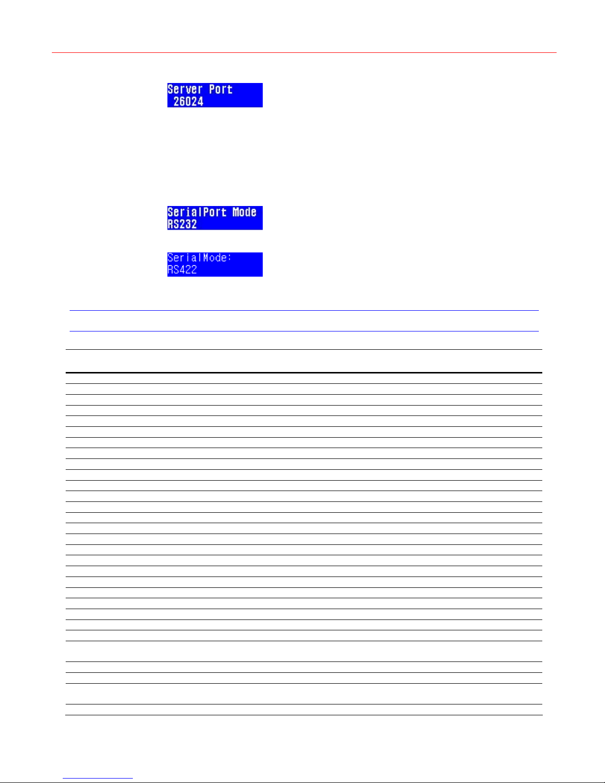
When the Maxpro port address menu shows on the LCD screen, input the port number, then
press Slider_Right to confirm the selection.
25
Page 30
Maxpro Mode
Figure 6-19 Maxpro Server Port
Setting Maxpro Serial Port Mode
In Figure 4-10, press Slider_Right and the following figure is displayed.
When the Maxpro port address menu shows on the LCD screen, input the port number, then
press Slider_Right to confirm the selection.
Figure 6-20 Maxpro Serial Port Mode – 1
Figure 6-21 Maxpro Serial Port Mode – 2
When all above has been set, press Alt followed by Clr to exit the setup menu.
Maxpro Key Code
Maxpro Ultrakey Lite Maxpro Ultrakey Lite Maxpro Ultrakey Lite
#1 Alarm #41 F1 #81 clr
#2 #42 #82 F10+Forward
#3 #43 Split #83 F10+F4
#4 F10 + ● #44 F10+Mon #84 F10+search
#5 F10 + set #45 F10+Split #85 Review
#6 #46 #86 F10+iris#7 #47 DVR #87 F10+iris+
#8 #48 F10+F9 #88 focus+
#9 #49 F10+F3 #89 focus#10 #50 F10+F1 #90 iris+
#11 F10+Alarm #51 F4 #91 iris#12 #52 #92 F10+focus+
#13 Seq #53 F10+F6 #93 F10+focus#14 F10+Seq #54 F10+F8 #94 PTZ call
#15 Set #55 F10+F5 #95 F10+PTZ call
#16 #56 #96
#17 #57 MonA #97
#18 #58 MonB #98
#19 #59 F10+MonA #99
#20 #60 F10+MonB #100 F10+F2
#21 F9 #61 Mon #101 F10+F7
#22 #62 1 #102
#23 F6 #63 2 #103
#24 F5 #64 3 #104
#25 F8 #65 F2 #105 Slider clockwise
#26 #66 4 #106
#27 #67 5 #107
#28 #68 6 #108
#29 #69 F7 #109
#30 #70 7 #110 F10+slider
Slider
counter-clockwise
F10+slider
clockwise
26
Page 31

Honeywell
counter-clockwise
#31 F3 #71 8
#32 #72 9
#33 #73 CAM
#34 #74 View
#35 #75 0
#36 #76 Ent
#37 #77 ●
#38 #78 Forward
#39 #79 Search
#40 #80 backward
27
Page 32
Standalone Mode
7 Standalone Mode
This chapter describes connection and configuration instructions of UltraKey Lite in
Standalone mode.
Standalone Mode Setup
The Standalone Mode is used to control DVR and PTZ.
Refer to “
Figure 7-1 Standalone main menu
Mode Selection” on page 10 to set the mode as STANDALONE.
Connection
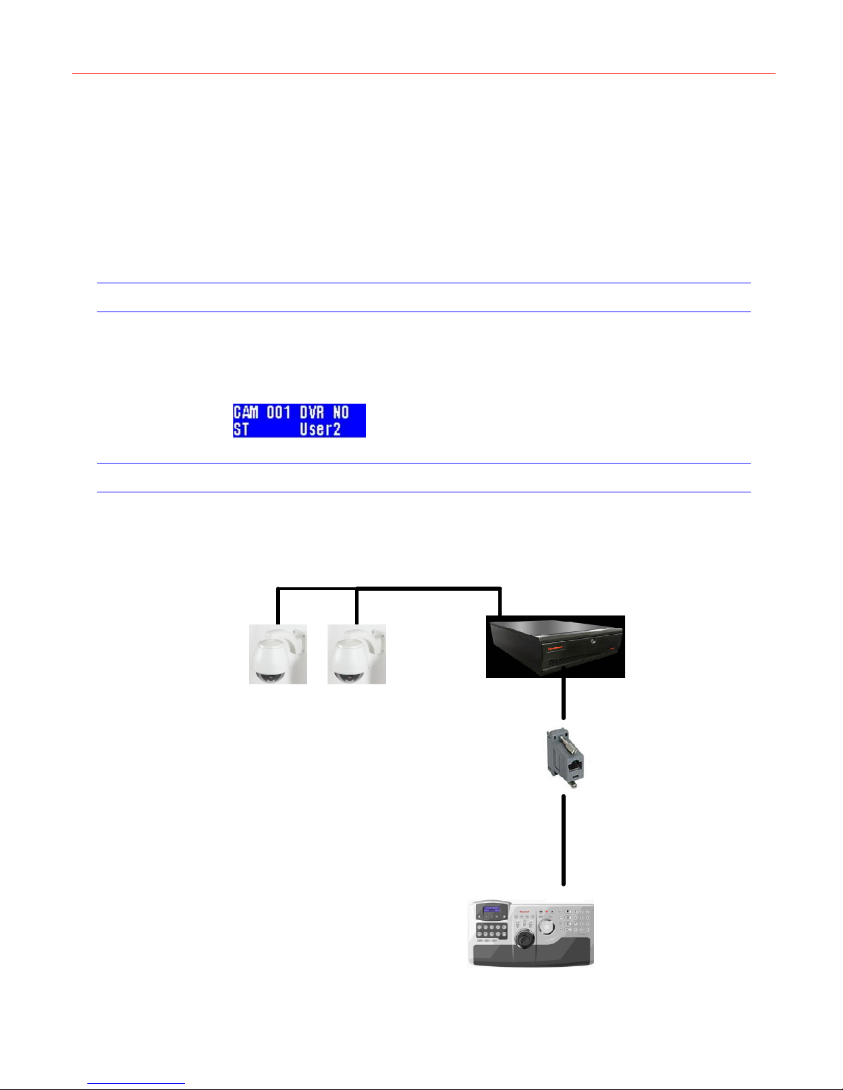
To connect PTZ with Ultrakey Lite, refer to the following figures:
Figure 7-2 Connecting PTZ by DVR Control
RJ45 to DB9F,
for RS232
Network
cable
28
Serial Port(RS232)
Ultrakey Lite
Page 33
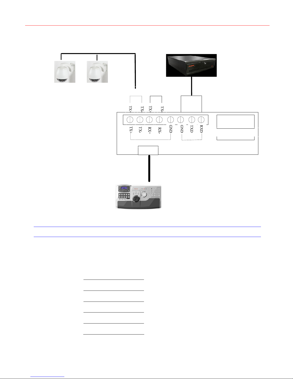
Figure 7-3 Connecting PTZ by Direct Control
RS485(COM1) RS485(COM2)
Honeywell
DVR
DB9 Male
2- TXD, 3- TXD, 5- GND
Fusion DVR
Keyboard Setup
Before using the Ultrakey Lite keyboard Fusion DVR function, it must be set-up to meet the
systems requirements.
Set COM2 according to the table below:
RS422(COM1) RS232(COM2)
RJ45
Network
cable
Serial Port
Ultrakey Lite
RS232(COM2)
Terminal Box
Type
Baud Rate
Parity
Data
Stop
RS232
9600
None
8
1
29
Page 34
Standalone Mode
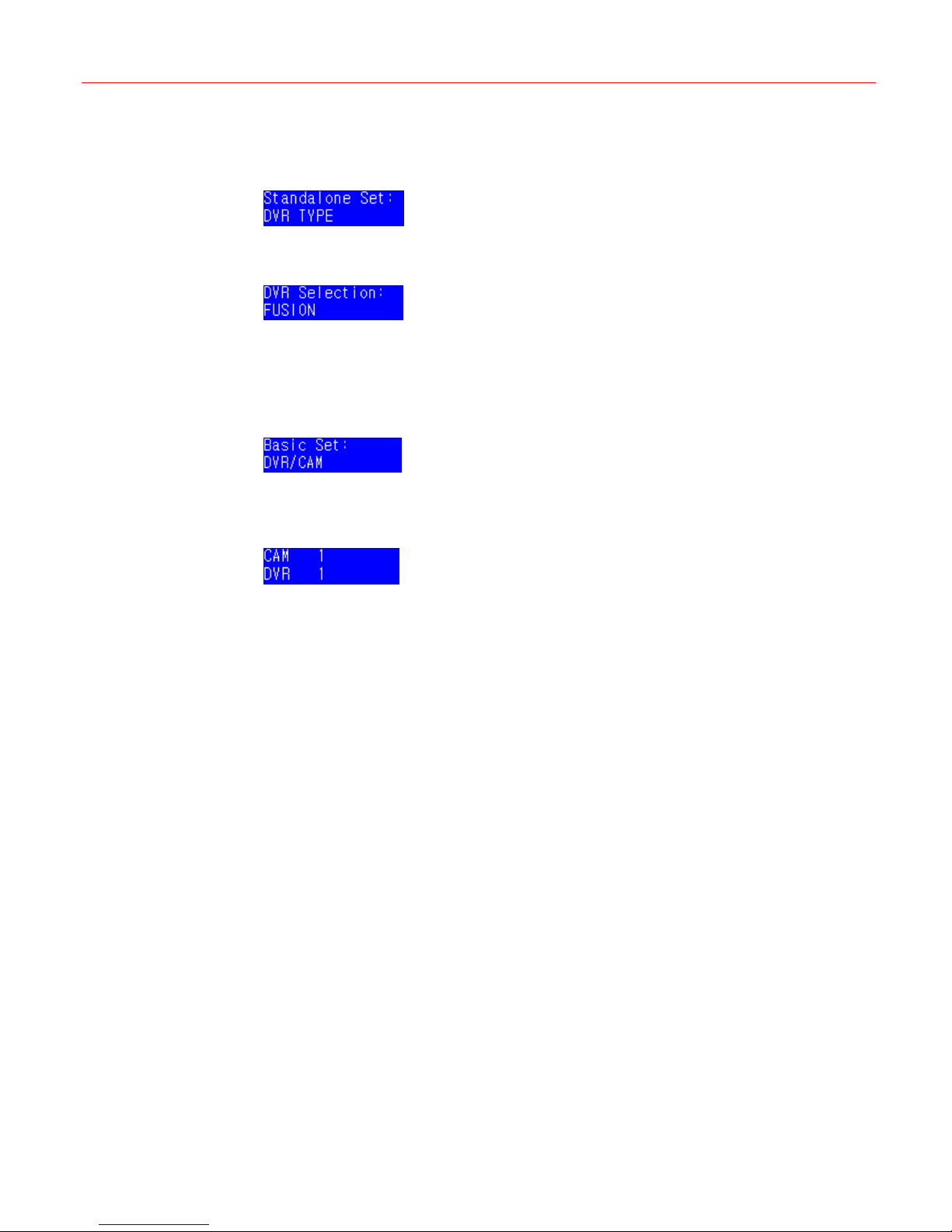
DVR Type
Press Select to enter the DVR Settings menu.
Figure 7-4 DVR TYPE
Press Slider_Right and rotate the slider, the following figure is displayed.
Figure 7-5 DVR Selection
Then press Slider_Right to select the DVR type as FUSION.
DVR and Camera Connection
Press Slider_Right to enter the Basic Set menu.
Figure 7-6 DVR/Camera
Rotate the slider to select the Camera, press Slider_Right to select the DVR.Press
Slider_Left to leave the menu and save the configuration.
Figure 7-7 DVR/CAM setting
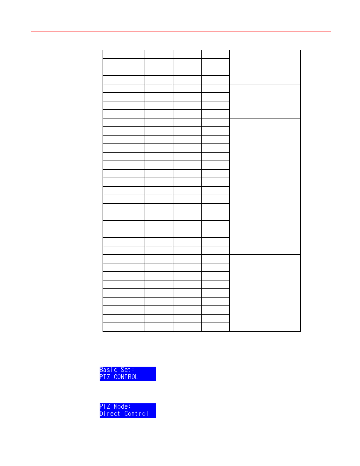
The keyboard can control 1, 4, 9 and 16-way DVRs.
Example:
If a system has 33 cameras with:
DVR 1, a 4-way DVR connected to cameras 1 through 4 inclusive
DVR 2, a 4-way DVR connected to cameras 5 through 8 inclusive
DVR 3, a 16-way DVR connected to cameras 9 through 24 inclusive
DVR 4, a 9-way DVR connected to cameras 25 through 33 inclusive
Then this system would be shown as in the table below:
30
Page 35
Honeywell
CAM 1 DVR 1
CAM 2 DVR 1
CAM 3 DVR 1
CAM 4 DVR 1
CAM 5 DVR 2
CAM 6 DVR 2
CAM 7 DVR 2
CAM 8 DVR 2
CAM 9 DVR 3
CAM 10 DVR 3
CAM 11 DVR 3
CAM 12 DVR 3
CAM 13 DVR 3
CAM 14 DVR 3
CAM 15 DVR 3
CAM 16 DVR 3
CAM 17 DVR 3
CAM 18 DVR 3
CAM 19 DVR 3
CAM 20 DVR 3
CAM 21 DVR 3
CAM 22 DVR 3
CAM 23 DVR 3
CAM 24 DVR 3
CAM 25 DVR 4
CAM 26 DVR 4
CAM 27 DVR 4
CAM 28 DVR 4
CAM 29 DVR 4
CAM 30 DVR 4
CAM 31 DVR 4
CAM 32 DVR 4
CAM 33 DVR 4
4 way DVR (DVR 1)
4 way DVR (DVR 2)
16 way DVR (DVR 3)
9 way DVR (DVR 4)
PTZ Mode
In Figure 7-6, press Slider_Down to enter the following menu.
Figure 7-8 PTZ Control
Press Slider_Right to enter the following menu.
Figure 7-9 Direct Control
31
Page 36

Standalone Mode
Figure 7-10 DVR Control
Rotate the slider to select the needed user type, and then press Slider_Right to confirm.
Operations
Note
Refer to
Refer to Figure 7-2 for connecting PTZ by DVR control.
Figure 7-3 for connecting PTZ by direct control.
DVR selection
Pressing a number followed by the DVR key selects a DVR to control. This also selects the
first camera controlled on that DVR.
Display
Display function can make DVR rotates different Live or Search display grid displays.
Example: 4A, 4B, 4C, 4D, 9A, 9B, 16 division screen display.
You can directly press Split on the keyboard and the DVR rotates next grid display form
current grid display. For example: if the current grid display is 4B, if you directly press Split the
DVR will change into 4C grid display.
You can also press one or two of the number keys followed by the Split key to make DVR
change into any kind of grid display.
Example:
Press… To display in…
4+1 + Split
4+2 + Split
4+3 + Split
4+4 + Split
9+1 + Split
9+2+Split
4A grid
4B grid
4C grid
4D grid
9A grid
9B grid
1+6+Split
Auto sequence
The function can toggle Auto Sequence on FUSION DVR (ON/OFF).
Press Seq to toggle Auto Sequence on Fusion DVR.
Alarm out
The function can toggle Relay (Alarm output) on specified channel.
Press the number key which is less than 5 followed by Alarm key to toggle Relay on specified
channel.
Instant record
The function can toggle Instant Record on specified channel.
Press the number key which presents for the specified channel followed by Recycle key to
toggle Instant Record on specified channel.
32
16 grid
Page 37

Honeywell
Full screen
The function can toggle Full Screen on specified channel.
Press number key, and Camera. Then press Ent.
Reverse play
The function can make DVR play backwards in search.
Press Backward to play backwards in search.
Stop function
The function can make DVR halt play movement.
Press Stop to halt play movement.
Play
The function can make DVR play forwards in search.
Press Review to play forwards in search.
Zoom function
While only one camera is selected in search, press Set to adjust the zoom level from level 1 to
level 5.
Search date set
The function can make DVR display the search menu to configure the date, month and time for
playback. Press Search to into the menu.
When the DVR is in the search play mode and has been configured the channel to play, user
can directly press F1 to display the menu.
Up, Down, Left, Right, Enter, Clear Keys
When setting conditions in the menu, refer to the following table for the keyboard operations to
control the Search date set menu.
Press… To…
F2 Up
F7 Down
F6 Left
F8 Right
Ent Confirm
Clr Esc
F3 F4 F5 F9 KEY FUNTION
Press F3 to display the video of the previously selected camera in full screen mode.
Press F4 to display the 4-split screen.
Press F5 to display the 9-split screen.
Press F9 to display the 16-split screen.
33
Page 38

Standalone Mode
HRHD DVR
Keyboard Setup
Operations
The HRHD DVR function setup is just like the FUSION DVR function setup except that the
HRHD type must be selected.
DVR selection
Pressing a number followed by the DVR key selects a DVR to control.
Number entry (for entering passwords)
To enter numbers, press and hold the Alt key and then press the number keys.
DVR menus
Press F1 to bring up the password screen. Press and hold the Alt key, and enter the password.
Then press Ent to start the access to the DVR set-up menus.
Navigation between these menu items is achieved by using the function keys indicated in the
table below:
Press… To…
Slider_Up or F2 Move up
Slider_Down or F7 Move down
Slider_Left or F6 Move left
Slider_Right or F8 Move right
Exit the current menu. (If the user presses F1
F1
Ent select an option
when in the ‘Set-up screen’, the DVR exits
the menus and returns to normal operation.)
or enter the menu
Picture control
The following table indicates the keys used for picture control:
Key Function
Split Display
Seq Sequence
F10 Freeze
Press Split to select the next display setting (in the cycle of ‘4x4’, ‘3x3’, ‘2x2’ and ‘PIP’).
Use the Slider_Left and Slider_Right keys to cycle through the other cameras when
displaying 2x2 and 3x3 displays.
The screen layout of the multi-camera displays can be set by pressing Ent, then Slider_Up,
Slider_Down, Slider_Left or Slider_Right keys to select an active camera (highlight box
displayed). Then press one or two of the number keys (to enter a legal camera number)
followed by the Camera key to select that number camera to be displayed in that cameo.
34
Page 39

Honeywell
Press Seq to put the DVR output into a sequence (the sequence depends on the current
display mode and set-up). If the key is pressed again, the sequence stops (displaying the
current step in the sequence).
Press F10 to freeze the current display. Press the key again to return to the ‘live’ picture(s).
Camera selection
Press one or two of the number keys (to enter a legal camera number) followed by the Camera
key to select that number camera for full-screen display on the DVR output. This also selects
the associated DVR.
Alarm function
If an alarm is active, press Alarm to reset the output of DVR (including internal buzzer).
If the DVR is in the live monitoring mode (and no alarm is active), press the Alarm key to
display the event log. (Once in the event log, it is navigated in the same way as the menus as
detailed in ‘DVR Menus‘).
If user password is enabled on the DVR, then pressing the Alarm key will
Note
Spot function
cause a user password screen to be displayed. If a user password is required,
enter the password just as ‘Number Entry’.
To display a camera on the spot monitor, press the Monitor key, then press one or two of the
number keys (to enter a legal camera number) followed by the Camera key to select that
number camera for display on the spot monitor.
Press Monitor then Seq to put the spot monitor into a camera sequence.
Instant record & panic record
The function can toggle Instant Record on specified channel.
User can press Recycle to toggle on/off the PANIC RECORD on specified channel.
Live/Search
Press Search to bring up the ‘Search’ menu. Press the key again to exit the ‘Search’ menu.
Play
The function can make DVR playback or pause.
User can directly press Review to playback or pause.
Stop function
The function can toggle between live monitor state and pause state.
User can directly press Stop key to realize this function.
Next frame
The function can show the next frame when the DVR is in pause state.
User can rotate clockwise the finger on the slider to realize this function when DVR is in pause
state.
Previous frame
The function can show the previous frame when the DVR is in pause state.
User can rotate counter clockwise the finger on the slider to realize this function when DVR is
in pause state.
35
Page 40
Standalone Mode
Cascade Control
Fast Forward
The function can make DVR playback fast.
User can directly press Forward to realize this function.
Rewind
The function can make DVR rewind fast.
User can directly press Backward to realize this function.
Zoom
Press Set to zoom the picture on the screen.
PTZ control
The function can let HJC5000 to control PTZ of HRXD.
User can directly press Alt+Set into PTZ control.
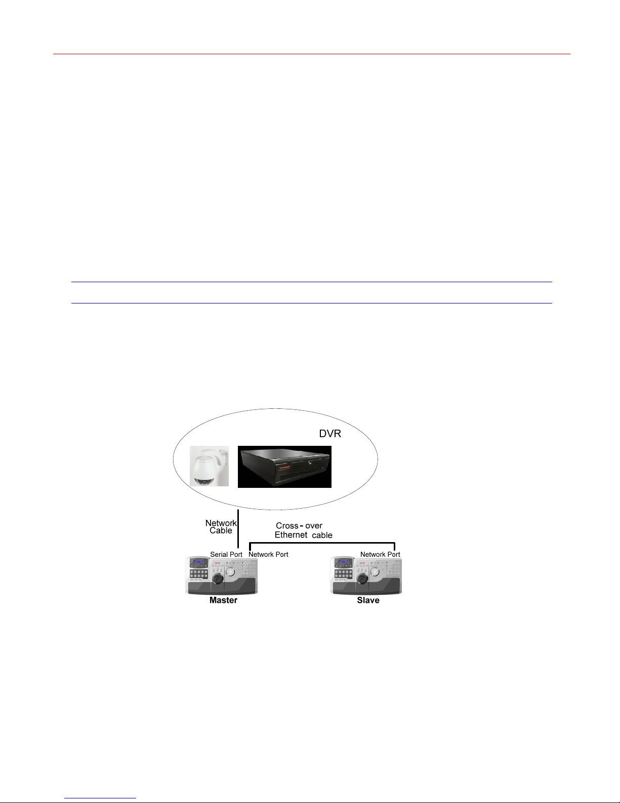
Several Ultrakey Lites can be cascaded to control DVR and PTZ.
Connection
There are two kinds of cascade connection as follows:
Figure 7-11 Cascade connectionⅠ
36
Page 41
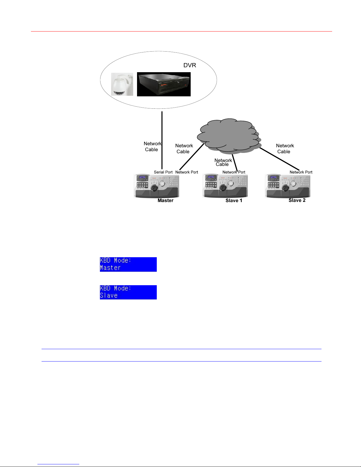
Figure 7-12 Cascade connectionⅡ
Honeywell
NETWORK
Cascade Setup
Refer to Cascade on page 16 to set the cascade control.
Figure 4-55, press Ent and the following figure is displayed.
In
Figure 7-13 KBD Mode – Master
Figure 7-14 KBD Mode – Slave
If the keyboard is the master, in
If the keyboard is the slave, in
In
Figure 4-56, press Ent and set up the IP address.
The slave’s IP address must be the same to the master’s address.
PTZ Control (Direct Control)
Figure 7-13 press Ent to confirm the selection.
Figure 7-14 press Ent to confirm the selection.
Keyboard Setup
For connecting of Ultrakey Lite and PTZ, refer to Figure 7-3.
Certain settings should be done to use the direct control of PTZ with Ultrakey Lite.
• Set COM1 (in Figure 4-10) according to the table below:
37
Page 42
Standalone Mode
Type
Baud Rate
Parity
Data
Stop
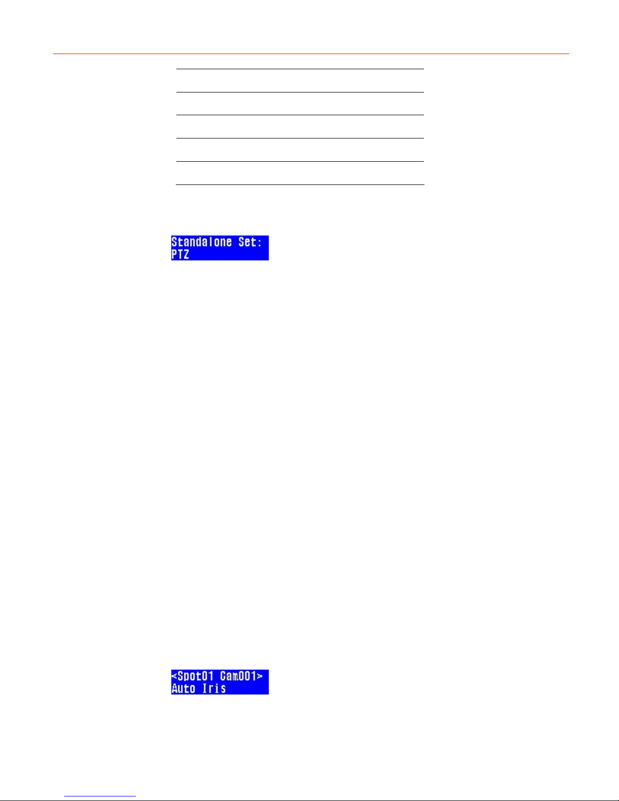
• In Standalone main menu (in Figure 7-1), press Select, and rotate the slider to enter
Figure 7-15 PTZ set
Camera Selecting
After keyboard setup and return to standalone main menu.
To select a camera for control, enter the camera number (1-128) using the numeric keypad
and press Camera.
Operations
RS485
1200, 9600, 19200 and so on
None/even/odd
7/8 bit
1/2 bit
“PTZ” Settings or Press PTZ. You can set PTZ Name, Address and Protocol.
Pan/Tilt
Use the joystick to control (pan and tilt) the camera. Move the joystick up and down for Tilt
functions and left and right for pan functions.
Zoom
Rotate the joystick knob clockwise/counterclockwise for zoom in/out functions.
Iris
Adjust the iris by pressing Iris (+) and Iris (-).
Focus
Press the Focus (+) or Focus (-) keys to manually focus the lens.
Preset
Program preset: Input number, press View, and then press Enter.
Run preset: Press the View, input number, and then press Enter.
PTZ
The PTZ call is used in Diamond protocol to control certain features of the KD6/HD6 PTZ
camera. Press PTZ call and the following figures are displayed by rotate the slider, and Press
Slider_Right to select.
Figure 7-16 PTZ – Auto Iris
38
Page 43
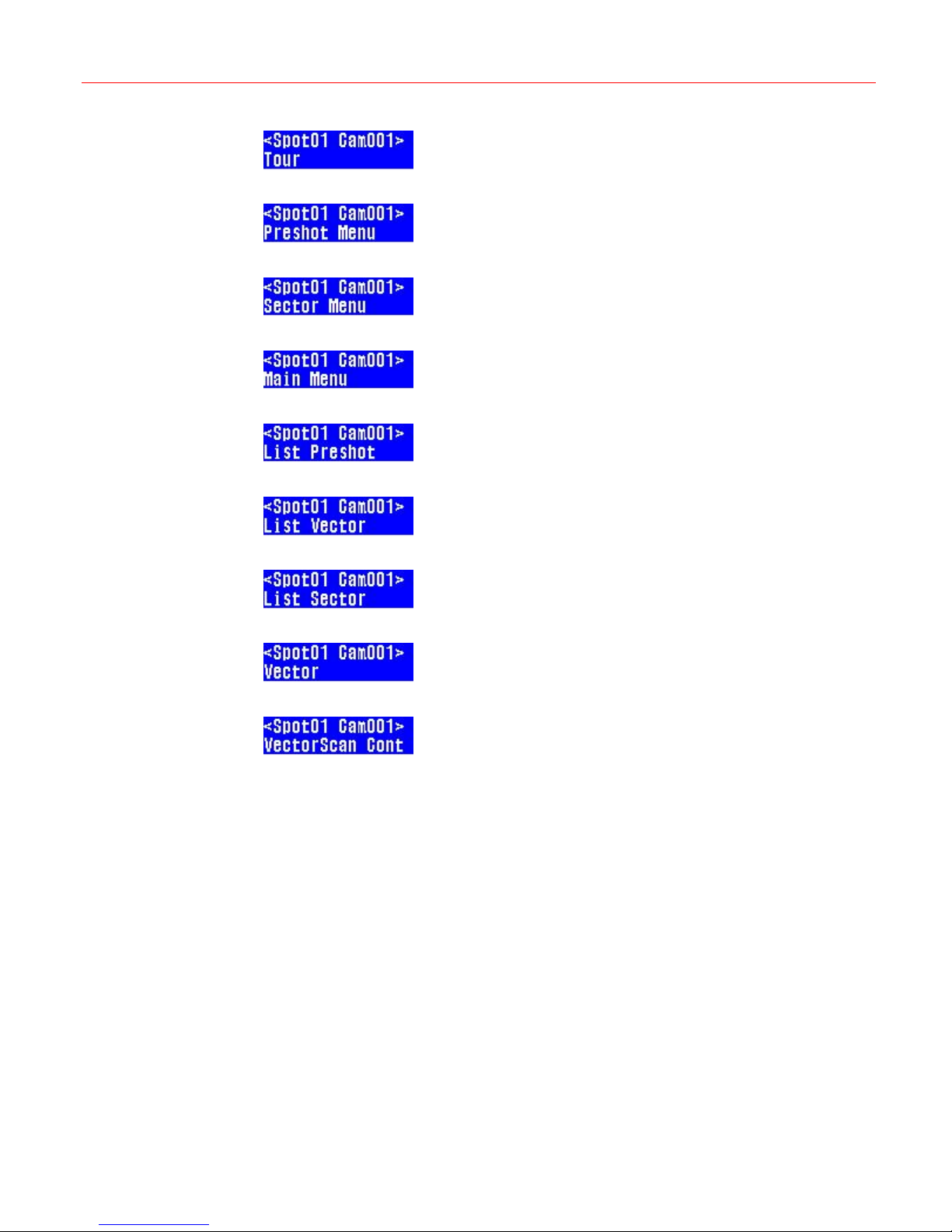
Figure 7-17 PTZ – Tour
Figure 7-18 PTZ – Preshot Menu
Figure 7-19 PTZ – Sector Menu
Figure 7-20 PTZ – Main Menu
Figure 7-21 PTZ – List Preshot
Figure 7-22 PTZ – List Vector
Honeywell
Figure 7-23 PTZ – List Sector
Figure 7-24 PTZ – Vector
Figure 7-25 PTZ – VectorScan Cont
39
Page 44
Web System
8 Web System
Login
This chapter describes how to configure Ultrakey Lite, upgrade its software or reboot the
system through Internet Explorer.
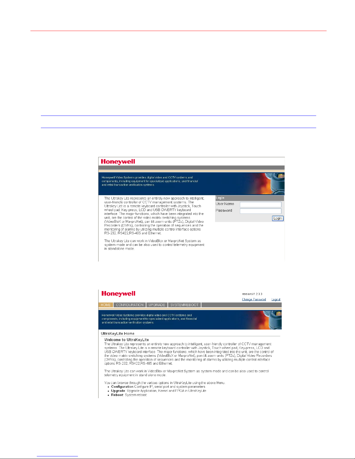
Input the IP address of Ultrakey Lite in the address bar and the following interface is displayed:
Figure 8-1 Honeywell Video System Main Page
Enter user name and password (default user name and password: admin/ultralite) and click
Login. The following figure is displayed:
Figure 8-2 Login and Home Page
40
Page 45
Configuration
In the CONFIGURATION tab, there are six configuration sections listed in the left pane (see
Figure 8-3): System, Standalone, Maxpro, VideoBloX, Serial Port and IP Configuration.
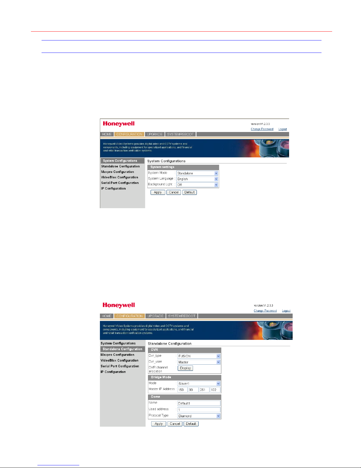
System Configuration
Click System Configuration in the left pane and the following figure is displayed:
Figure 8-3 System Configurations
Honeywell
System Mode – select one mode among Standalone, VideoBloX and Maxpro.
System Language – select the menu language of Ultrakey Lite.
Background Light – disable or adjust the background light brightness of the LCD: Off, Low,
Middle and High.
Click Apply to save the configuration; Cancel to give up the configuration; Default to restore
all default values.
Standalone Configuration
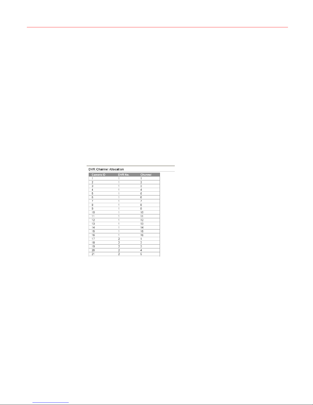
Click Standalone Configuration in the left pane and the following figure is displayed:
Figure 8-4 Standalone Configuration
41
Page 46
Web System
DVR
• Type – select one DVR type to be used.
• User – set the DVR as master or slave.
• Channel allocation – click Display to view channels of all the DVRs and Cameras, as
shown in
Bridge Mode (cascaded connection)
Figure 8-5.
• Mode – set the keyboard as Master or slave in a cascade connection.
• If the keyboard is used as slave, it must be assigned with the master’s IP address in
Master IP Address.
Dome
• Name – enter the name of the dome.
• Used address – enter the address of the dome.
• Protocol Type – select the control protocol of the dome.
Click Apply to save the configuration; Cancel to give up the configuration; Default to restore
all default values.
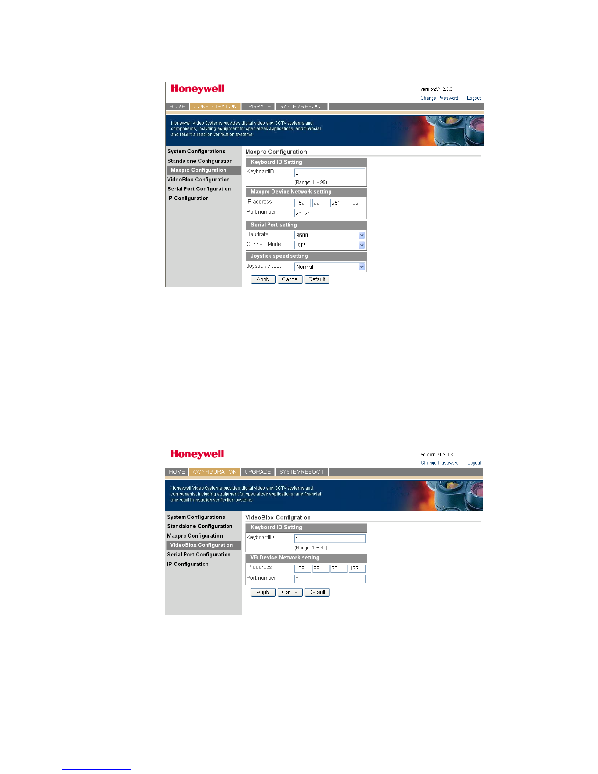
Figure 8-5 DVR Channel Allocation
Maxpro Configuration
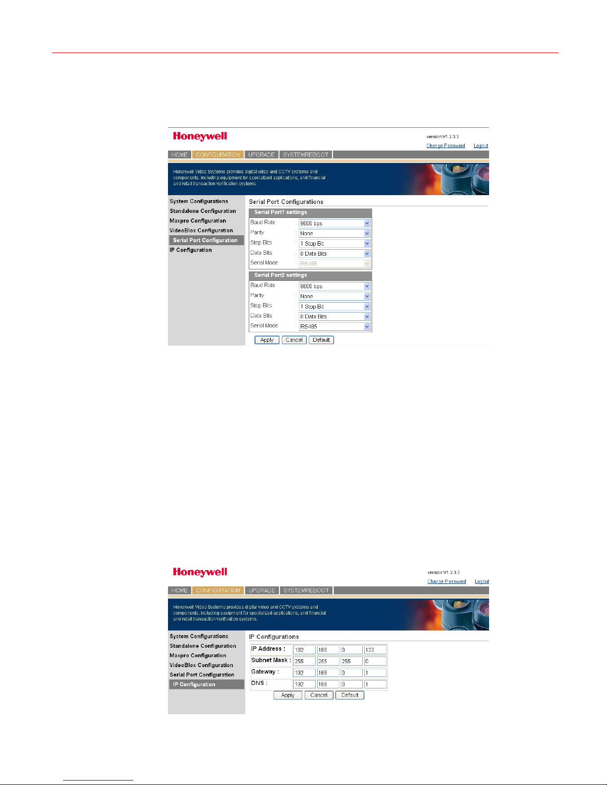
Click Maxpro Configuration in the left pane and the following figure is displayed:
42
Page 47
Honeywell
Figure 8-6 Maxpro Configuration
Keyboard ID Setting – set the ID of the keyboard (range: 1~99).
Maxpro Device Network Setting – set the IP address and port number of the Maxpro device.
Serial Port Setting – set the baud rate and connection mode of the serial port.
Joystick Speed Setting – set the joystick speed to slow or fast.
Click Apply to save the configuration; Cancel to give up the configuration; Default to restore
all default values.
VideoBloX Configuration
Click VideoBloX Configuration in the left pane and the following figure is displayed:
Figure 8-7 VideoBloX Configuration
Keyboard ID Setting – set the ID of the keyboard (range: 1~99).
VB Device Network Setting – set the IP address and port number of the VideoBloX device.
Click Apply to save the configuration; Cancel to give up the configuration; Default to restore
all default values.
43
Page 48
Web System
Serial Port Configuration
Click Serial Port Configuration in the left pane and the following figure is displayed:
Figure 8-8 Serial Port Configuration
Serial Port1 Settings
• Baud Rate – select the proper baud rate of for the serial port.
• Parity – set the parity.
• Stop Bits – select the proper stop bit.
• Data Bits – select the proper data bit.
• Serial Mode – select the proper mode for the serial port.
The same configuration can be made in “Serial Port2 Settings” section.
Click Apply to save the configuration; Cancel to give up the configuration; Default to restore
all default values.
IP Configuration
Click IP Configuration in the left pane and the following figure is displayed:
Figure 8-9 IP Configuration
44
Page 49
Upgrade
Honeywell
Enter IP address, subnet mask, gateway and DNS.
Click Apply to save the configuration; Cancel to give up the configuration; Default to restore
all default values.
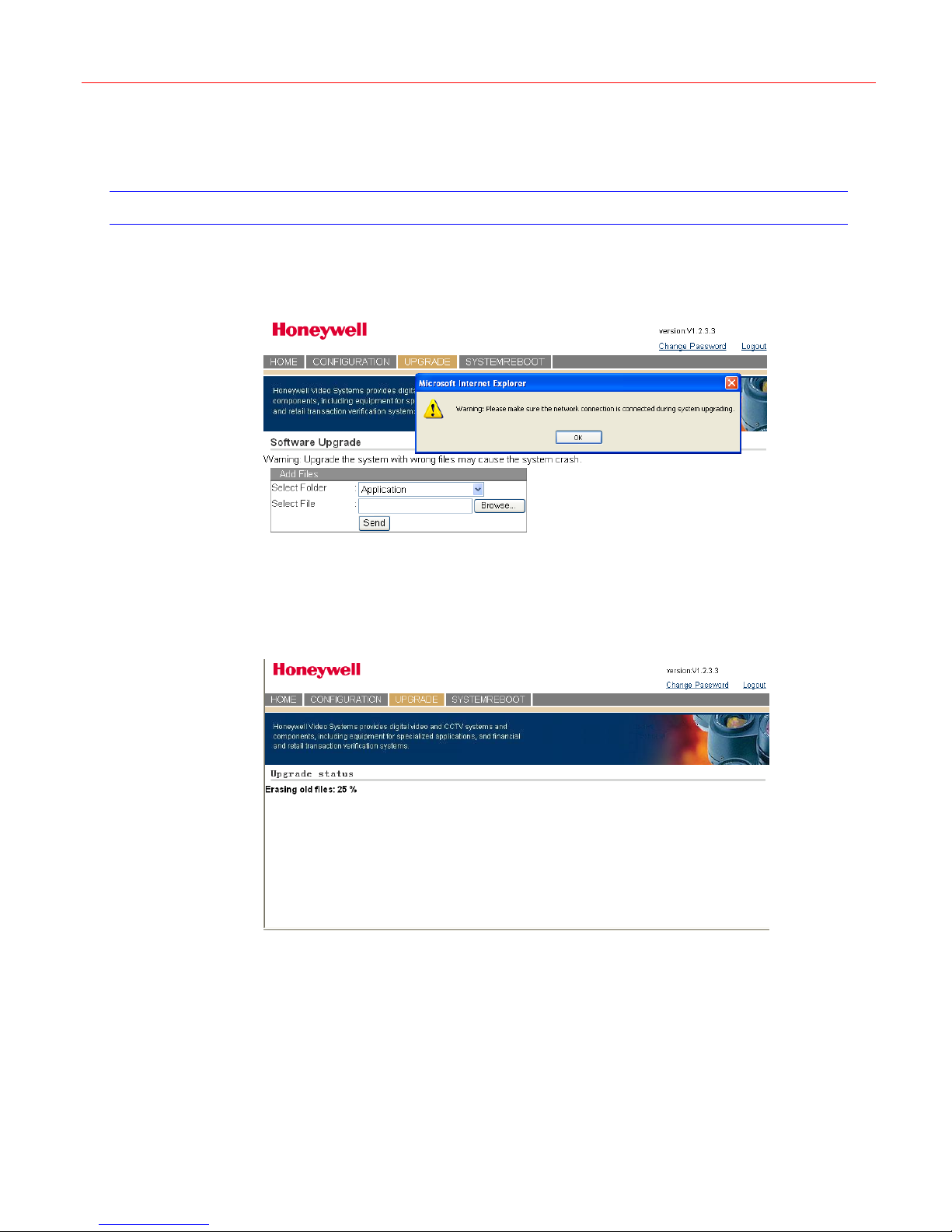
To upgrade the firmware of the keyboard, click the UPGRADE tab and the following figure is
displayed:
Figure 8-10 Upgrade
A warning window is displayed to remind you to make sure the network is connected during
the upgrade. Click OK to close the warning.
Select the corresponding firmware folder to be upgraded (application, FPGA, Kernel or slider
firmware) and specify the file. Click Send to start the upgrade.
Figure 8-11 Upgrade status (Erasing old files)
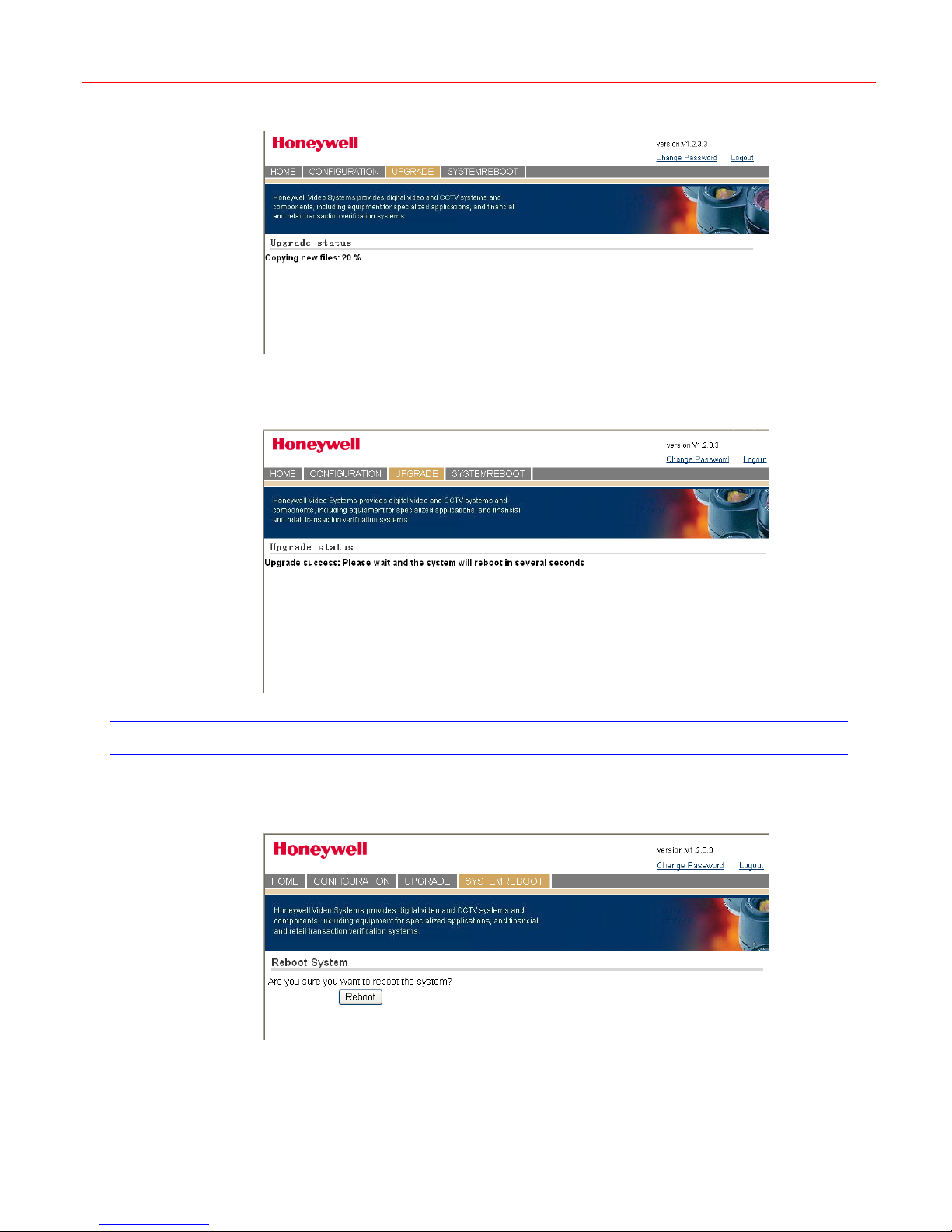
After erasing the old files, it starts coping new files as shown in the following figure:
45
Page 50
Web System
Figure 8-12 Upgrade status (Copying new files)
The following figure displays when the upgrade is completed successively, and then the
system will reboot.
Figure 8-13 Upgrade status (Upgrade success)
System Reboot
In the SYSTEMREBOOT tab, the operator can reboot the keyboard from network.
Figure 8-14 System Reboot
Click Reboot to restart the keyboard.
46
Page 51
Change Password
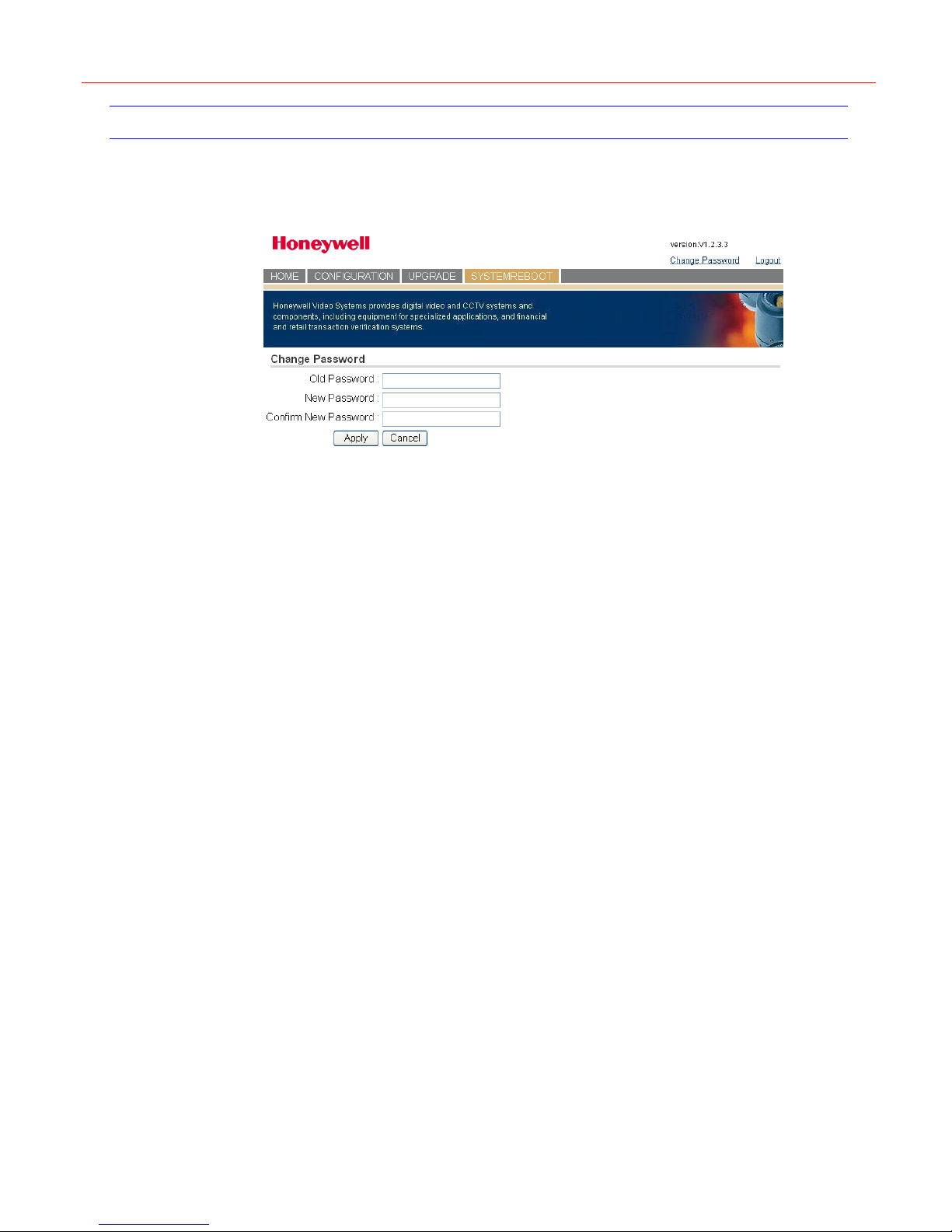
To change the password of the current user, click Change Password at the top right corner
and the following figure is displayed:
Figure 8-15 Change Password
Enter the current password, the new password and confirm it. Click Apply to set the new
password or Cancel to keep the current password.
Honeywell
47
Page 52

Appendix 1: PCKZ-CAS Keyboard Map
9 Appendix 1: PCKZ-CAS Keyboard Map
The following table shows the key value map between Ultrakey Lite and PCKZ-CAS keyboard.
As the Ultrakey Lite include all the functions the PCKZ-CAS keyboard has, pressing the certain
key on the Ultrakey Lite will have the same effect as pressing the corresponding key on the
PCKZ-CAS keyboard.
Ultrakey Lite PCKZ-CAS Ultrakey Lite PCKZ-CAS
1 1 F5 PTZ Slots
2 2 Alt+F5 Door
3 3 F6 User1
4 4 Alt+F6 HardCount
5 5 F7 User2
6 6 Alt+F7 SoftCount
7 7 F8 User3
8 8 Alt+F8 Cash Slots
9 9 F9 User4
0 0 Alt+F9 Cash Cage
Alt+PTZ call AutoPan F10 PTZ Cas
ent ENTER Alt+F10 Back House
SLIDER_KEY_UP
SLIDER_KEY_DOWN
SLIDER_KEY_LEFT
SLIDER_KEY_RIGHT
Seq Seq Review
Alarm Alarm ACK Search
Login Login Logout DVR Recall
set Menu ● Store
CAM Cam Recycle Aux3
MONITOR Mon ◄|| Prev
DVR VCR ||► Next
F1 P clr Clear
Alt+F1 Group13 view PTZ F1
F2 BJ tour PTZ F2
Alt+F2 Group14 PTZ call PTZ F3
F3 AR MonA Aux 1
Alt+F3 Group15 Alt+MonA < -F4 PB MonB Aux2
Alt+F4 Group16 Alt+Mon B Aux4
↑
↓
←
→
Focus (C) Focus(N)
Focus (+)
Iris (-)
Iris (+)
Focus(F)
Iris(C)
Iris(O)
Zoom(-)
Zoom(+)
48
Page 53
10 Appendix 2: USB Keyboard Map
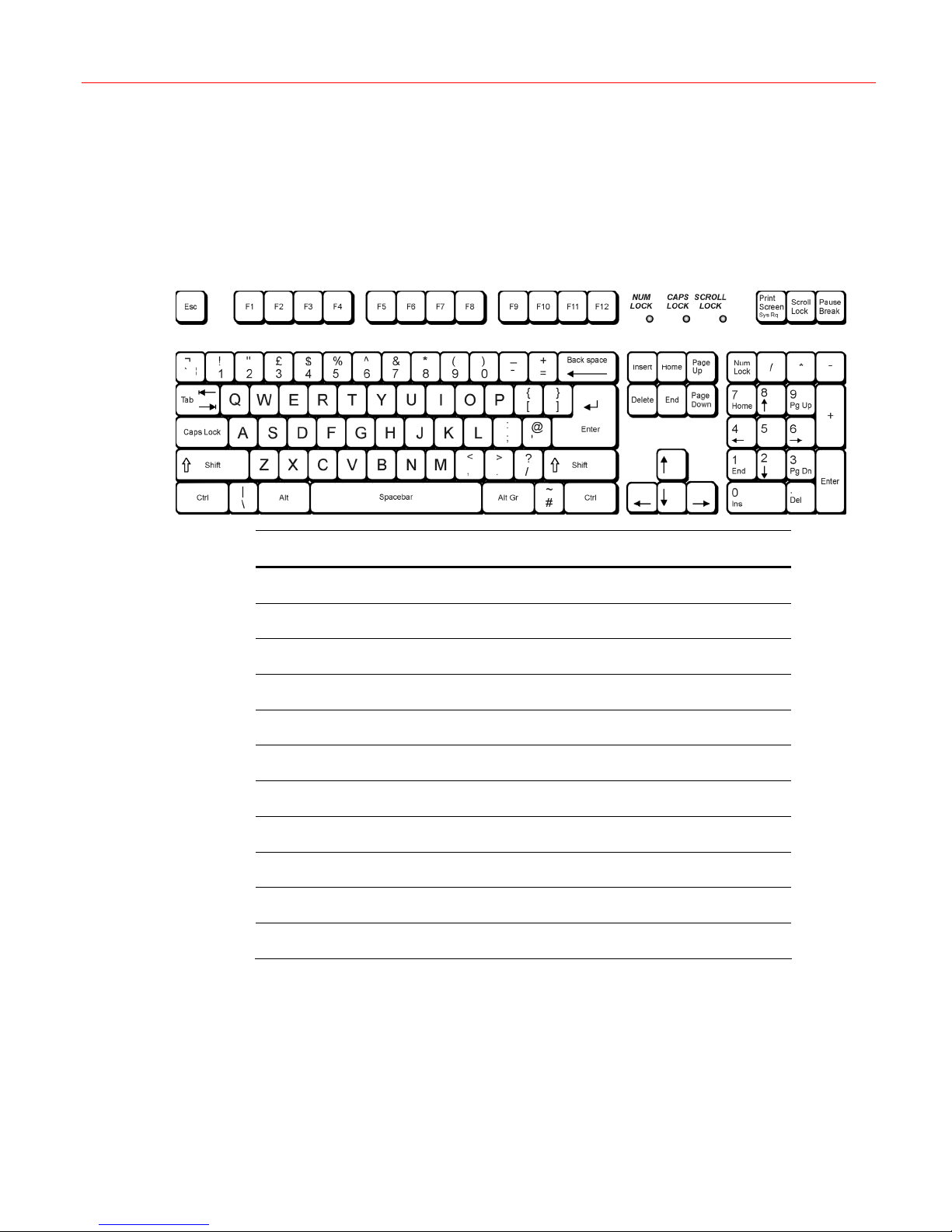
The general USB keyboard is supported.
Honeywell
USB keyboard Ultrakey Lite
ESC CLR
F1~F10 F1~F10
F12 LOGIN
F11 Setup
0~9 0~9
Alt Alt
Left Left
Right Right
Up Up
Down Down
A~Z (it is not case sensitive)
The keys, which are not listed in the table, are not used.
49
Page 54

Honeywell Video Systems (Head Office)
2700 Blankenbaker Pkwy, Suite 150
Louisville, KY 40299, USA
www.honeywellvideo.com
TEL: +1.800.796.2288
Honeywell Security Australia Pty Ltd.
Unit 5, Riverside Centre, 24-28 River Road West
Parramatta, NSW 2150, Australia
www.ademco.com.au
TEL: +61.2.8837.9300
Honeywell Security Asia Pacific
35/F Tower A, City Center, 100 Zun Yi Road
Shanghai 200051, China
www.security.honeywell.com/cn
TEL: +86 21.5257.4568
Honeywell Security Asia
Flat A, 16/F, CDW Building, 388 Castle Peak Road
Tsuen Wan, N.T., Hong Kong
www.security.honeywell.com/hk
TEL: +852.2405.2323
Honeywell Security France
Parc Gutenberg, 8, Voie La Cardon
91120, Palaiseau, France
www.honeywell.com/security/fr
TEL: +33.01.64.53.80.40
Honeywell Security Italia SpA
Via Treviso 2 / 4
31020 San Vendemiano
Treviso, Italy
www.honeywell.com/security/it
TEL: +39.04.38.36.51
Honeywell Security España
Mijancas 1. 3
P.Ind. Las Mercedes
28022 Madrid, Spain
www.security.honeywell.com/es
TEL: +34.902. 667.800
a Planta
Honeywell Video Systems Northern Europe
Netwerk 121
1446 WV Purmerend, The Netherlands
www.SecurityHouse.nl
TEL: +31.299.410.200
Honeywell Video Systems UK Ltd.
Aston Fields Road, Whitehouse Ind Est
Runcorn, Cheshire, WA7 3DL, UK
www.honeywellvideo.com
TEL: +0844 8000 235
Honeywell Security South Africa
Unit 6 Galaxy Park, 17 Galaxy Avenue
Linbro Park, P.O. Box 59904
2100 Kengray, Johannesburg, South Africa
www.honeywell.co.za
TEL: +27.11.574.2500
Honeywell Security Deutschland
Johannes-Mauthe-Straße 14
D-72458 Albstadt, Germany
www.honeywell.com/security/de
TEL: +49.74 31.8 01.0
Honeywell Security Poland
Chmielewskiego 22a, 70-028
Szczecin, Polska
www.ultrak.pl
TEL: +48.91.485.40.60
Honeywell Security Czech Republic
Havránkova 33, Brno
Dolní Heršpice, 619 00, Czech Republic
www.olympo.cz
TEL: +420.543.558.111
Honeywell Security Slovakia Republic
Vajnorská 142, 83104 Bratislava
Slovakia
www.olympo.sk
TEL: +421.2.444.54.660
© 2008 Honeywell International Inc. All rights reserved. No part of this publication may be reproduced by any means
without written permission from Honeywell Video Systems. The information in this publication is believed to be accurate in
all respects. However, Honeywell Video Systems cannot assume responsibility for any consequences resulting from the
use thereof. The information contained herein is subject to change without notice. Revisions or new editions to this
publication may be issued to incorporate such changes.
Honeywell
Video Systems
www.honeywellvideo.com
+1.800.796.CCTV (North America only)
 Loading...