

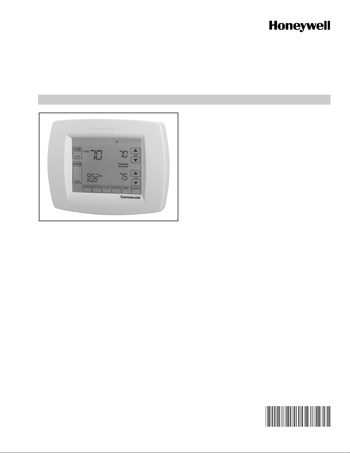
TB8220 Commercial VisionPRO™
Programmable Thermostat
VISIONPRO™ 8000 TOUCHSCREEN
FEATURES
• Large, clear display with backlight shows the current
and set temperature and time—even in the dark.
• Menu-driven programming make setup effortless.
• Beautiful ergonomic design is smart and sophisticated
to match your customers’ lifestyle.
• Touchscreen interaction
• Real-time clock keeps time during power failures and
automatically updates to daylight savings.
• “Saving Changes” notification lets you know when the
schedule changes have been saved.
• Change reminders let you know when to replace the
batteries.
• Holiday Override options allow you to override the
program schedule, as desired.
APPLICATION
The TB8220 Commercial VisionPRO™ 8000 Touchscreen
Programmable Thermostat is an effortless, seven-day
programmable thermostat that provides universal system
compatibility, precise comfort control and is easy-to-program.
• Speedy same-schedule programming—no need to
copy multiple days.
• Armchair programming allows you to remove the
thermostat from the wall for programming.
PRODUCT DATA
The TB8220 provides temperature control for gas, oil, electric
and heat pumps for up to 2 heat, 2 cool systems.
Contents
Application......................................................................... 1
Specifications .................................................................... 2
Ordering Information ......................................................... 2
Installation ......................................................................... 4
Wiring ................................................................................ 5
Installer Setup ................................................................... 12
Operation........................................................................... 18
Troubleshooting (Table 11) ................................................ 23
63-2625—1
TB8220 COMMERCIAL VISIONPRO™ PROGRAMMABLE THERMOSTAT
SPECIFICATIONS
Thermostat Description: See Table 1.
Electrical Ratings: See Table 2.
Temperature:
Ratings:
Operating Ambient:
TB8220: 0°F to 120°F (-18°C to 49°C).
C7089U, C7189U: 5% to 95%.
Shipping: -30 °F to 150 °F (-34.4°C to 65.6°C).
Display Accuracy: ±1°F (±0.5°C).
Setpoint:
Range:
Heating: 40°F to 90°F (4°C to 32°C).
Cooling: 50°F to 99°F (10°C to 37°C).
Default Settings: See Table 3.
Humidity Ratings (RH, non-condensing):
TB8220 VisionPRO Thermostats: 5% to 90%.
C7089U, C7189U: 5% to 95%.
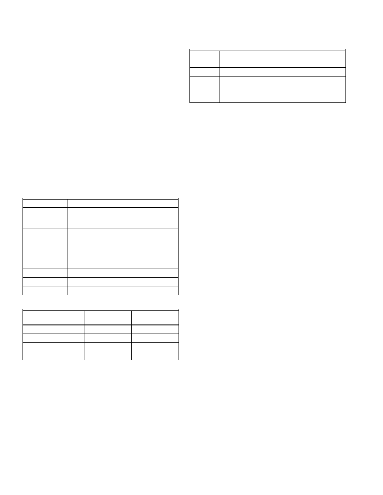
Table 1. Thermostat Description.
Feature Description
Powering
methods
System types
(up to
2 heat/2 cool)
Changeover Manual or Auto changeover selectable
System setting Heat-Off-Cool-Auto
Fan setting Auto-On
Terminal
W (Heating) 20 - 30 Vac 0.02 - 1.0A
Y (Cooling) 20 - 30 Vac 0.02 - 1.0A
G (Fan) 20 - 30 Vac 0.02 - 0.60A
A (Economizer/TOD) 20 - 30 Vac 0.02 - 1.0A
• Battery only
• 24 Vac only
• 24 Vac with battery backup
• Gas or electric heat with air conditioning
• Warm air, hot water, high-efficiency
furnaces, and heat pumps
• Heat only
• Heat only with fan
• Cool only
Table 2. Electrical Ratings
Voltage
(50/60 Hz) Running Current
Table 3. Energy Star Default Program Settings.
Schedule
Period Time
Occ1 8:00am 70°F (21°C) 75°F (24°C) On
Unocc1 10:00pm 55°F (10°C) 85°F (29.5°C) Auto
Occ2 — — — —
Unocc2 — — — —
Cycle Rates (at 50% Load):
Heating: Selectable 1 - 12 cycles per hour.
Cooling: Selectable 1 - 6 cycles per hour.
Interstage Differential:
Droopless control. Once the first stage is running at 90% load,
the thermostat energizes the second stage.
Cool Indication: Displays “Cool On” when Cool is activated.
Heat Indication: Displays “Heat On” when Heat is activated.
Auxiliary Heat Indication: Displays “Aux. Heat On” when
Auxiliary Heat is activated.
Clock Accuracy: ±1 minute per month.
Finish:
TB8000: Premier White® color.
C7189U Wall Mount Remote Indoor Sensor: Premier White®
color.
T7770A Wall Mount Remote Indoor Sensor: Premier White®
color.
Batteries:
Three replaceable AAA alkaline batteries: Power thermostat
when 24 Vac common is not used.
Non-replaceable lithium battery with ten-year life: Under nor-
mal conditions holds calendar and time settings.
NOTE: Alkaline batteries keep calendar and time if lithium
battery is no longer functional.
Resistance Characteristics of Remote Sensors:
C7089U Outdoor Sensor: 10K ohm NTC.
C7189U Remote Indoor Sensor: 10K ohm NTC.
C7772 Flush-Mount Remote Indoor Sensor: 20K ohm NTC.
T7770A1006 Wall-Mount Remote Indoor Sensor: 20K ohm
NTC.
T7770A3002 Wall-Mount Remote Indoor Sensor: 10K ohm
NTC.
Setpoints
Fan
SettingHeat Cool
ORDERING INFORMATION
When purchasing replacement and modernization products from your TRADELINE® wholesaler or distributor, refer to the
TRADELINE® Catalog or price sheets for complete ordering number.
If you have additional questions, need further information, or would like to comment on our products or services, please write or
phone:
1. Your local Honeywell Automation and Control Products Sales Office (check white pages of your phone directory).
2. Honeywell Customer Care
1885 Douglas Drive North
Minneapolis, Minnesota 55422-4386
In Canada—Honeywell Limited/Honeywell Limitée, 35 Dynamic Drive, Scarborough, Ontario M1V 4Z9.
International Sales and Service Offices in all principal cities of the world. Manufacturing in Australia, Canada, Finland, France,
Germany, Japan, Mexico, Netherlands, Spain, Taiwan, United Kingdom, U.S.A.
63-2625—1 2
TB8220 COMMERCIAL VISIONPRO™ PROGRAMMABLE THERMOSTAT
Calibration (TB8220, C7089U, C7189U, T7770A):
No field calibration required.
Mounting Means:
TB8220: Direct wall-mount using mounting screws and
anchors provided. Fits standard vertical or horizontal
2 in. x 4 in. junction box.
C7089U: Mounts outside of living space with mounting clip and
screws provided.
C7189U, T7770A: Mounts directly on the wall using mounting
screws and anchors provided. Fits a vertical 2 x 4 in. junction box.
Cover Plate:
32003796-001 Cover Plate is used to cover marks left on the
wall by the old thermostat.
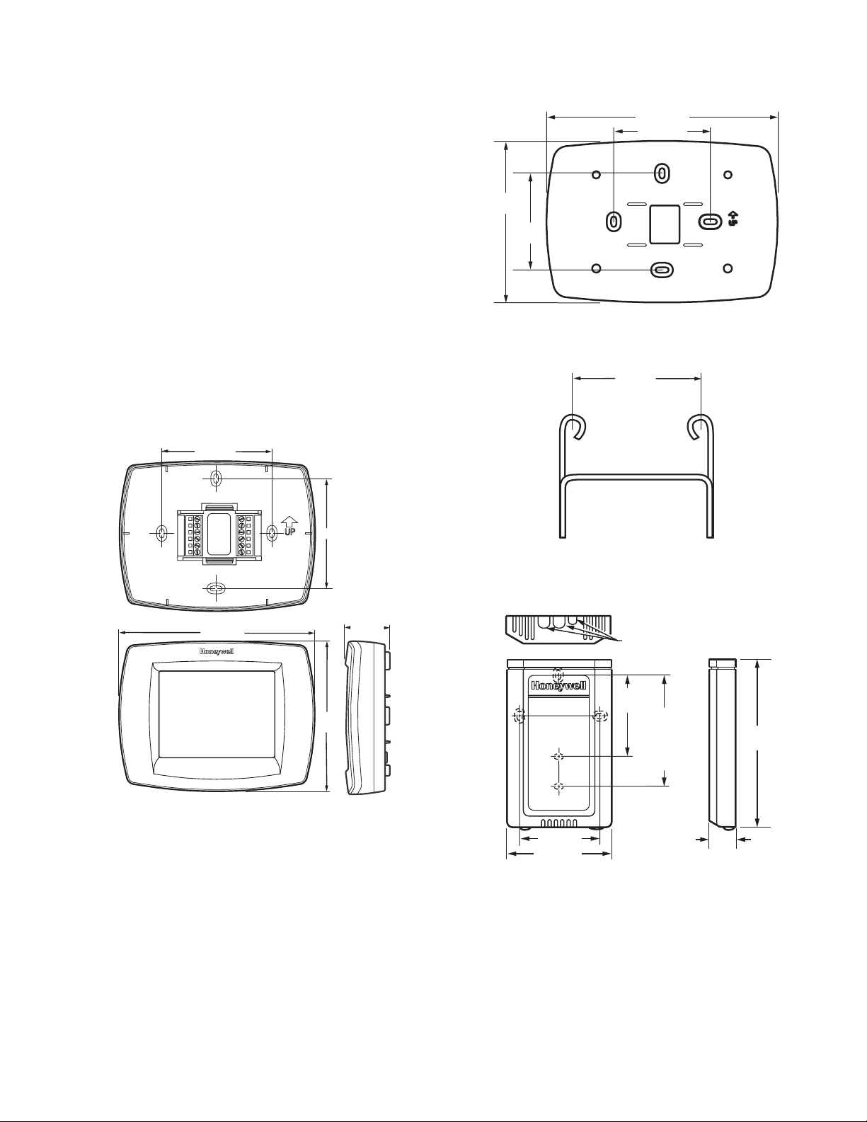
Dimensions:
TB8220 Touchscreen Thermostat: See Fig. 1.
C7089U Outdoor Sensor Mounting Clip: See Fig. 3.
C7189U Remote Indoor Sensor: see Fig. 5.
T7770A: See Fig. 4.
32003796-001 Cover Plate: See Fig. 2.
WALLPLATE
3-3/8 (86)
7-7/8 (200)
3-5/16 (84)
5-1/2
(140)
3-5/16
(84)
M22139
Fig. 2. 32003796-001 Cover Plate dimensions in in. (mm).
1-1/2 (38)
3-3/8 (86)
THERMOSTAT
THERMOSTAT
6 (152)
AND WALLPLATE
4-9/16
(116)
1-3/8 (35)
M22421
Fig. 1. TB8220 Touchscreen Thermostat
dimensions in in. (mm).
M4488
Fig. 3. C7089U Outdoor Sensor Mounting Clip
dimensions in in. (mm).
KNOCKOUTS FOR
EUROPEAN APPLICATIONS
2-3/8
(60)
STANDARD
2-3/8 (60)
3-3/16 (80)
UTILITY
CONDUIT
BOX (2 X 4)
MOUNTING
HOLES
15/16
(23)
5-1/16
(128)
M22936
Fig. 4. T7770A dimensions in in. (mm).
3 63-2625—1

TB8220 COMMERCIAL VISIONPRO™ PROGRAMMABLE THERMOSTAT
4-5/8
(117)
1-1/8
(29)
M4465
2-3/4 (70)
FRONT VIEW SIDE VIEW
Fig. 5. C7189U Indoor Sensor dimensions in in. (mm).
MERCURY NOTICE
If this control is replacing a control that contains
mercury in a sealed tube, do not place your old
control in the trash. Dispose of properly.
Contact your local waste management authority
for instructions regarding recycling and the proper
disposal of an old control.
NO
M22258
NO
NO
YES
5 FEET
[1.5 METERS]
Fig. 6. Select thermostat location.
Do not install the thermostat where it can be affected by:
— Drafts or dead spots behind doors and in corners.
— Hot or cold air from ducts.
— Radiant heat from sun or appliances.
— Concealed pipes and chimneys.
— Unheated (uncooled) areas such as an outside wall behind
the thermostat.
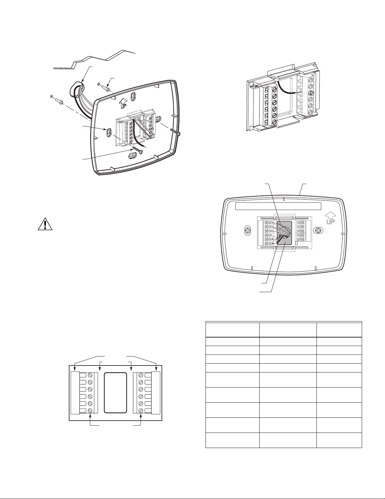
Separate Wallplate from Thermostat
1. Separate the wallplate from the thermostat. See Fig. 7.
WALLPLATE
INSTALLATION
When Installing this Product...
1. Read these instructions carefully. Failure to follow them
could damage the product or cause a
hazardous condition.
2. Check ratings given in instructions and on the product to
ensure the product is suitable for your application.
3. Installer must be a trained, experienced service
technician.
4. After installation is complete, check out product
operation as provided in these instructions.
CAUTION
Electrical Shock or Equipment Damage Hazard.
Can shock individuals or short equipment
circuitry.
Disconnect power supply before installation.
Select Thermostat Location
Select a location for the thermostat about 5 ft (1.5m) above the
floor in an area with good air circulation at average
temperature. See Fig. 6.
WIRE HOLE
THERMOSTAT
M22267
Fig. 7. Separate wallplate from thermostat.
Install Wallplate (See Fig. 8)
Mount the thermostat horizontally on the wall:
1. Pull the wires through the wire hole on the wallplate.
2. Position the wallplate on the wall with the arrow pointing
up. Level the wallplate for appearance only.
3. Use a pencil to mark the mounting holes.
4. Remove the wallplate from the wall and drill two 3/16 in.
holes in the wall (if drywall) as marked. For firmer
material such as plaster, drill two 7/32 in. holes. Tap the
wall anchors (provided) into the drilled holes until flush
with the wall.
5. Pull the wires through the wire hole on the wallplate and
position the wallplate over the wall anchors.
6. Insert the mounting screws into the wall anchors and
tighten.
63-2625—1 4
WALL
WIRES THROUGH WALL
AND WIRE SLOT
WALL ANCHORS (2)
TB8220 COMMERCIAL VISIONPRO™ PROGRAMMABLE THERMOSTAT
3. Insert the wires into the terminal block and tighten each
screw terminal. See Fig. 10.
MOUNTING
HOLES
MOUNTING
SCREWS (2)
M19916
Fig. 8. Install wallplate.
WIRING
CAUTION
Electrical Shock Hazard.
Can cause electrical shock or equipment damage.
Disconnect power supply before connecting wiring.
IMPORTANT
— All wiring must agree with applicable codes,
ordinances and regulations.
— Use 18 gauge thermostat wire. Shielded cable is not
required.
NOTES:
— Refer to Table 5 for terminal designation
descriptions.
— See Fig. 12 through 22 for wiring diagrams for
specific equipment applications.
1. Select set of terminal identifications that correspond to
your system type (conventional or heat pump). See Fig. 9.
HEAT PUMP
CONVENTIONAL
Y2
W1
S1
S2
Y2
L
A
W2
S1
S2
SCREW TERMINALS
RC
R
W
Y
G
C
Fig. 9. Terminal identifications for system type.
2. Loosen screw terminals used for the application.
RC
R
O/B
Y
G
C
M22780
M19917
Fig. 10. Insert wires into terminal block.
4. Push excess wire back into the wall opening and restrict
wires to the shaded area. See Fig. 11.
5. Plug the wall opening with nonflammable insulation to
prevent drafts from affecting the thermostat.
WIRE
WALL OPENING
SHADED AREA
WALLPLATE
M22266
Fig. 11. Restrict wires to shaded area of wire hole.
Table 4. Wiring Diagrams.
System Type
Wallplate Terminal
Identifications
Wiring Diagram
Figure
Standard Heat/Cool Conventional 12, 13
Heat Only Conventional 14
Heat Only with Fan Conventional 15
Cool only Conventional 16
Standard Multistage
Conventional 17, 18
up to 2 Heat/2 Cool
Heat Pump
Heat Pump 19, 20
(No Auxiliary Heat)
Heat Pump
Heat Pump 21, 22
(with Auxiliary Heat)
Multiple T7770A
— 27, 28, 29
Sensors
Multiple C7189U
—30
Sensors
5 63-2625—1
TB8220 COMMERCIAL VISIONPRO™ PROGRAMMABLE THERMOSTAT
Table 5. Terminal Designation Descriptions. NOTES:
Terminal
Designation Description
Rc
(see Note 1)
R
(see Note 1)
Power for cooling—connect to secondary side
of cooling system transformer.
Power for heating—connect to secondary side
of heating system transformer.
Y Compressor output.
C
(see Note 2)
Common wire from secondary side of cooling
system transformer.
W Heat relay.
GFan relay.
W2 Second stage heat relay.
Y2 Second stage cooling.
O/B
Changeover valve for heat pumps.
(see Note 3)
A
(see Note 4)
S1
Economizer/Time-Of-Day (TOD) output—
powered via R terminal.
Optional outdoor or indoor remote sensor.
(See Note 5)
S2
Optional outdoor or indoor remote sensor.
(See Note 5)
L Powers red LED behind plastic in upper right
corner of the thermostat.
1. When used in a single-transformer system, leave
metal jumper wire in place between Rc and R. If
used on a two-transformer system, remove metal
jumper wire between Rc and R.
2. Common wire is optional when thermostat is used
with batteries. When using separate transformers
for heating and cooling, the common must come
from the cooling transformer.
3. If thermostat is configured for a heat pump in the
Installer Setup, configure changeover valve for
cool (O-factory setting) or heat (B).
4. Reference economizer literature for wiring details.
When set for economizer operation, the A terminal
provides the occupancy signal. (Power indicates
occupied.)
5. Sensor wires must have a cable separate from the
thermostat control cable.
Terminal “A” Wiring Details for Economizers
— Wire the A terminal to the W7212 “N” terminal, or the
W7459 “TR” terminal.
— When using dual transformers at the thermostat, the
heating transformer must power the economizer.
— The A signal is powered from the R terminal and energizes
the economizer to signal occupied status and drive the
damper to the set minimum position.
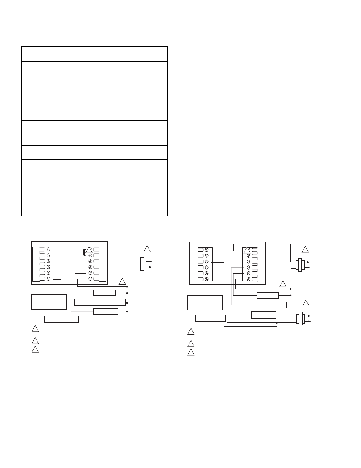
Conventional System Wiring
Y2
L
A
W2
S1
S2
OUTDOOR/INDOOR
TEMPERATURE
SENSOR
ECONOMIZER
POWER SUPPLY. PROVIDE DISCONNECT MEANS AND OVERLOAD
1
PROTECTION AS REQUIRED.
2
FACTORY INSTALLED JUMPER.
3
WHEN USING BATTERIES, THE 24V COMMON CONNECTION
IS OPTIONAL.
Fig. 12. Typical wiring of single transformer 1H/1C system.
RC
2
R
W
Y
G
C
FAN RELAY
COMPRESSOR CONTACTOR
HEAT RELAY
24 VAC
3
1
L1
(HOT)
L2
M22781A
Y2
L
A
W2
S1
S2
OUTDOOR/INDOOR
TEMPERATURE
SENSOR
ECONOMIZER
POWER SUPPLY. PROVIDE DISCONNECT MEANS AND OVERLOAD
1
PROTECTION AS REQUIRED.
2
REMOVE FACTORY INSTALLED JUMPER.
3
WHEN USING BATTERIES, THE 24V COMMON CONNECTION
IS OPTIONAL. WHEN USED, THE COMMON MUST CONNECT
TO THE COOLING TRANSFORMER SECONDARY.
RC
2
2
R
W
Y
G
C
FAN RELAY
COMPRESSOR CONTACTOR
HEAT RELAY
24 VAC
3
24 VAC
1
L1
(HOT)
L2
1
L1
(HOT)
L2
M22782A
Fig. 13. Typical hookup of dual transformer 1H/1C system.
63-2625—1 6
TB8220 COMMERCIAL VISIONPRO™ PROGRAMMABLE THERMOSTAT
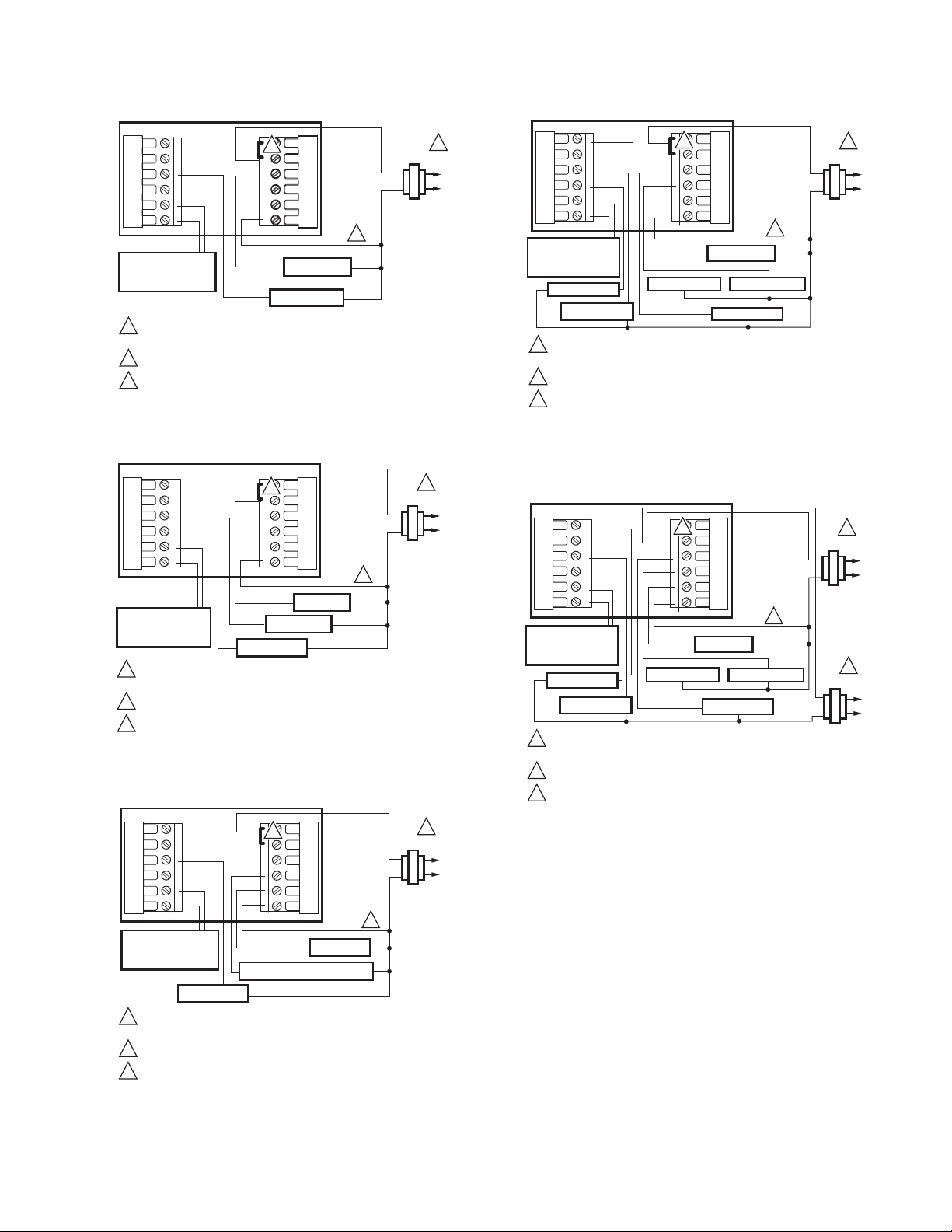
Y2
L
A
W2
S1
S2
OUTDOOR/INDOOR
TEMPERATURE
SENSOR
POWER SUPPLY. PROVIDE DISCONNECT MEANS AND OVERLOAD
1
PROTECTION AS REQUIRED.
2
FACTORY INSTALLED JUMPER.
3
WHEN USING BATTERIES, THE 24V COMMON CONNECTION IS
OPTIONAL.
RC
R
W
Y
G
C
2
2
HEAT RELAY
ECONOMIZER
3
24 VAC
1
L1
(HOT)
L2
M22783A
Fig. 14. Typical hookup of heat-only system.
Y2
L
A
W2
S1
S2
OUTDOOR/INDOOR
TEMPERATURE
SENSOR
POWER SUPPLY. PROVIDE DISCONNECT MEANS AND OVERLOAD
1
PROTECTION AS REQUIRED.
2
FACTORY INSTALLED JUMPER.
3
WHEN USING BATTERIES, THE 24V COMMON CONNECTION
IS OPTIONAL.
RC
2
R
W
Y
G
C
HEAT RELAY
ECONOMIZER
FAN RELAY
24 VAC
3
1
L1
(HOT)
L2
M22784A
Fig. 15. Typical hookup of heat-only system with fan.
Y2
L
A
W2
S1
S2
OUTDOOR/INDOOR
TEMPERATURE
SENSOR
ECONOMIZER
POWER SUPPLY. PROVIDE DISCONNECT MEANS AND OVERLOAD
1
PROTECTION AS REQUIRED.
2
FACTORY INSTALLED JUMPER.
3
WHEN USING BATTERIES, THE 24V COMMON CONNECTION
IS OPTIONAL.
RC
2
R
W
Y
G
C
FAN RELAY
COMPRESSOR CONTACTOR
24 VAC
3
1
L1
(HOT)
L2
M22785A
Fig. 16. Typical hookup of cool-only system.
Y2
L
A
W2
S1
S2
OUTDOOR/INDOOR
TEMPERATURE
SENSOR
HEAT RELAY 2
ECONOMIZER
1
POWER SUPPLY. PROVIDE DISCONNECT MEANS AND
OVERLOAD PROTECTION AS REQUIRED.
2
FACTORY INSTALLED JUMPER.
3
WHEN USING BATTERIES, THE 24V COMMON CONNECTION
IS OPTIONAL.
RC
2
R
W
Y
G
C
COOL RELAY 2
FAN RELAY
COOL RELAY 1
HEAT RELAY 1
3
24 VAC
1
L1
(HOT)
L2
M22786A
Fig. 17. Typical hookup of single transformer multistage
system (up to 2H/2C).
Y2
L
A
W2
S1
S2
OUTDOOR/INDOOR
TEMPERATURE
SENSOR
HEAT RELAY 2
ECONOMIZER
POWER SUPPLY. PROVIDE DISCONNECT MEANS AND
1
OVERLOAD PROTECTION AS REQUIRED.
2
REMOVE FACTORY INSTALLED JUMPER.
3
WHEN USING BATTERIES, THE 24V COMMON CONNECTION
IS OPTIONAL. WHEN USED, THE COMMON MUST CONNECT
TO THE COOLING TRANSFORMER SECONDARY.
RC
2
R
W
Y
G
C
FAN RELAY
COOL RELAY 2
COOL RELAY 1
HEAT RELAY 1
24 VAC
3
24 VAC
1
L1
(HOT)
L2
1
L1
(HOT)
L2
M22787A
Fig. 18. Typical hookup of dual transformer multistage
system (up to 2H/2C).
7 63-2625—1
TB8220 COMMERCIAL VISIONPRO™ PROGRAMMABLE THERMOSTAT
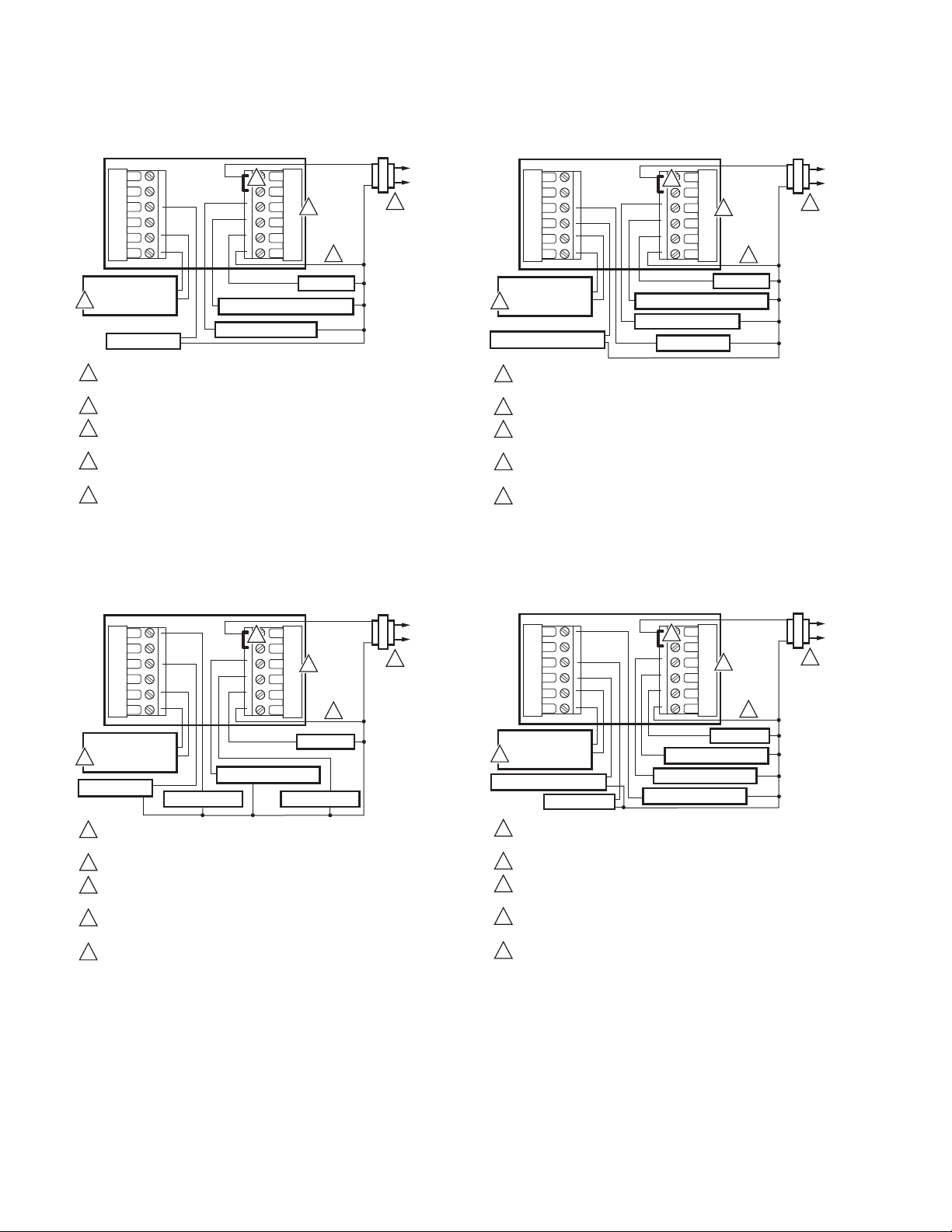
Heat Pump System Wiring
L1
(HOT)
Y2
L
A
W1
S1
S2
OUTDOOR/INDOOR
TEMPERATURE
5
SENSOR
ECONOMIZER
POWER SUPPLY. PROVIDE DISCONNECT MEANS AND OVERLOAD
1
PROTECTION AS REQUIRED.
2
FACTORY INSTALLED JUMPER.
WHEN USING BATTERIES, THE 24V COMMON CONNECTION
3
IS OPTIONAL.
4
"O/B" TERMINAL SET TO CONTROL AS EITHER "O" OR "B"
IN THE INSTALLER SETUP.
OPTIONAL OUTDOOR OR INDOOR REMOTE SENSOR.
5
WIRES MUST HAVE A CABLE SEPARATE FROM THE
THERMOSTAT CABLE.
COMPRESSOR CONTACTOR
CHANGEOVER VALVE
RC
2
R
O/B
Y
G
C
24 VAC
4
3
FAN RELAY
L2
1
M22788B
Fig. 19. Typical hookup of single-stage heat pump with no
auxiliary heat (1H/1C).
L1
(HOT)
Y2
L
A
W1
S1
S2
OUTDOOR/INDOOR
TEMPERATURE
5
SENSOR
AUXILIARY HEAT RELAY
POWER SUPPLY. PROVIDE DISCONNECT MEANS AND OVERLOAD
1
PROTECTION AS REQUIRED.
2
FACTORY INSTALLED JUMPER.
WHEN USING BATTERIES, THE 24V COMMON CONNECTION
3
IS OPTIONAL.
4
"O/B" TERMINAL SET TO CONTROL AS EITHER "O" OR "B"
IN THE INSTALLER SETUP.
OPTIONAL OUTDOOR OR INDOOR REMOTE SENSOR.
5
WIRES MUST HAVE A CABLE SEPARATE FROM THE
THERMOSTAT CABLE.
COMPRESSOR CONTACTOR
CHANGEOVER VALVE
RC
2
R
O/B
Y
G
C
ECONOMIZER
24 VAC
4
3
FAN RELAY
L2
1
M22790B
Fig. 21. Typical hookup of single-stage heat pump with
auxiliary heat (2H/1C).
L1
(HOT)
Y2
L
A
W1
S1
S2
OUTDOOR/INDOOR
TEMPERATURE
5
SENSOR
ECONOMIZER
POWER SUPPLY. PROVIDE DISCONNECT MEANS AND OVERLOAD
1
PROTECTION AS REQUIRED.
2
FACTORY INSTALLED JUMPER.
WHEN USING BATTERIES, THE 24V COMMON CONNECTION
3
IS OPTIONAL.
4
"O/B" TERMINAL SET TO CONTROL AS EITHER "O" OR "B"
IN THE INSTALLER SETUP.
OPTIONAL OUTDOOR OR INDOOR REMOTE SENSOR.
5
WIRES MUST HAVE A CABLE SEPARATE FROM THE
THERMOSTAT CABLE.
COMPRESSOR 2
CHANGEOVER VALVE
RC
2
O/B
COMPRESSOR 1
R
Y
G
C
24 VAC
4
3
FAN RELAY
L2
1
M22789B
Fig. 20. Typical hookup of multistage heat pump with no
auxiliary heat (2H/2C).
Y2
L
A
W1
S1
S2
OUTDOOR/INDOOR
TEMPERATURE
5
SENSOR
AUXILIARY HEAT RELAY
ECONOMIZER
POWER SUPPLY. PROVIDE DISCONNECT MEANS AND OVERLOAD
1
PROTECTION AS REQUIRED.
2
FACTORY INSTALLED JUMPER.
WHEN USING BATTERIES, THE 24V COMMON CONNECTION
3
IS OPTIONAL.
4
"O/B" TERMINAL SET TO CONTROL AS EITHER "O" OR "B"
IN THE INSTALLER SETUP.
OPTIONAL OUTDOOR OR INDOOR REMOTE SENSOR.
5
WIRES MUST HAVE A CABLE SEPARATE FROM THE
THERMOSTAT CABLE.
RC
2
R
O/B
Y
G
C
COMPRESSOR 1
CHANGEOVER VALVE
COMPRESSOR 2
24 VAC
4
3
FAN RELAY
Fig. 22. Typical hookup of multistage heat pump
with auxiliary heat (3H/2C).
L1
(HOT)
L2
1
M22791B
63-2625—1 8
 Loading...