

Page 1
APPLICATIONS
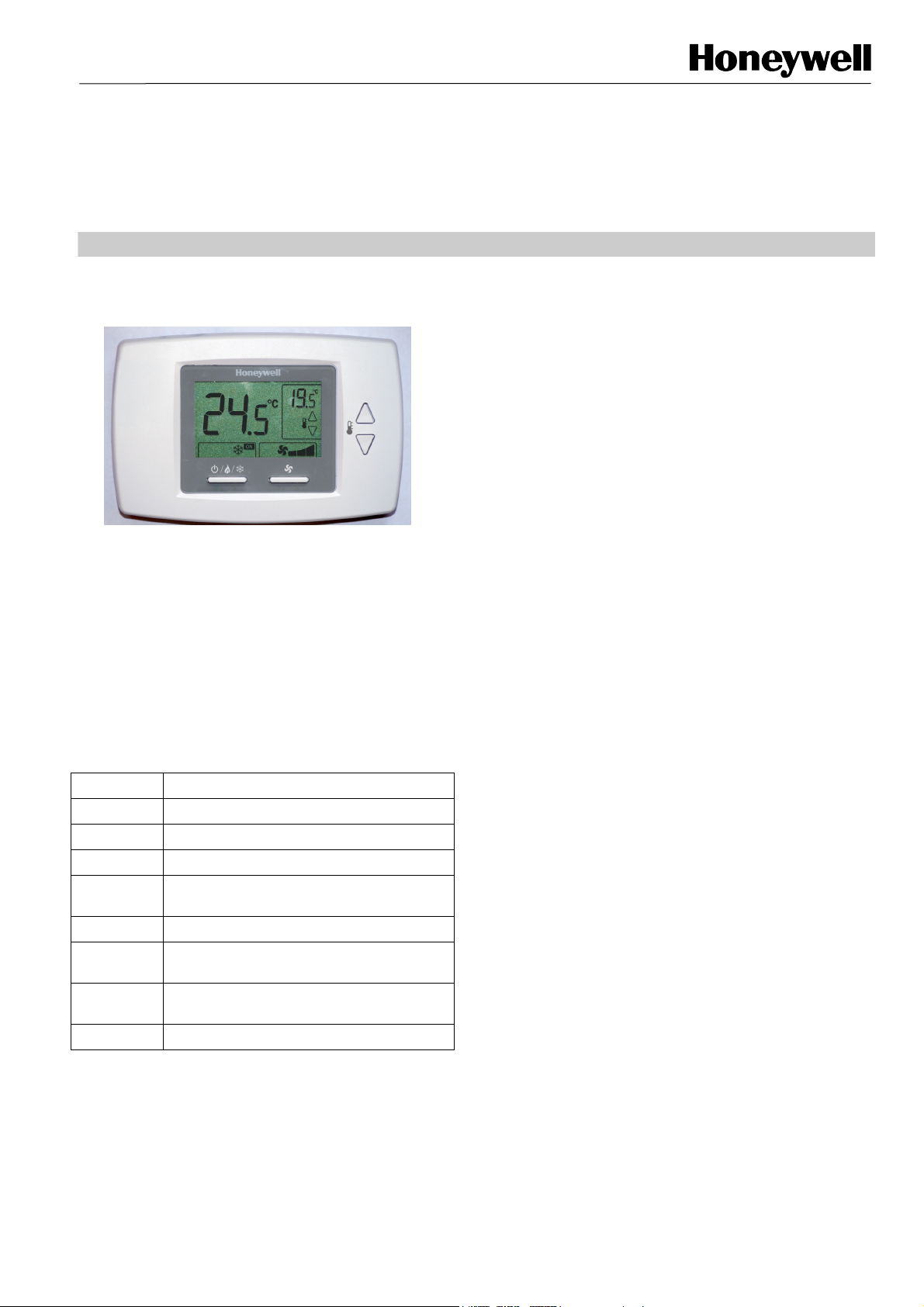
The T6590 range of digital thermostats is designed to control
the valves, fan and auxiliary electric heater within fan-coil
systems.
Modern, attractive styling and comprehensive feature set
makes the T6590 suitable for a wide range of applications.
There are a total of 8 application configurations supported,
and these are:
Application Description
0 2 pipe system, heating only
1 2 pipe system, cooling only
2 2 pipe system, 1 stage heat or 1 stage cool
3 2 pipe system, 1 stage heat or 1 stage cool,
auto changeover
4 4 pipe system 1 stage heat and 1 stage cool
5 4 pipe system 1 stage heat and 1 stage cool
auto changeover
6 2 pipe system, 1 stage heat or 1 stage cool
with auxiliary electric heater
7 4 pipe system, mixed manual and auto
The different applications can be selected from the installer
setup mode and by altering the external wiring connections
T6590 Series
FAN-COIL CONTROLLER
PRODUCT DATA
FEATURES
• Large, easy to read LCD display with backlight
• Heat / Cool or standby mode displayed on LCD
• Lockable keypad
• Room setpoint adjustable via simple-to-use up/down
buttons
• Fan speed ON/Off, low/med/high or auto
• Auto mode, fan speed is proportional to distance of room
temperature from setpoint
• Manual or automatic heat / cool changeover
• Control of auxiliary electric heater
• Inbuilt or remote sensor (NTC20K) options available
• Simultaneous display of room temperature and user
setpoint
• Push button adjustment of setpoint
• Switches allow manual control of system operation
and fan speed
• Special energy savings mode activated by external
input from Energy Management System (EMS) – a
window contact or hotel card-key - overrides the
temperature setting to installer defined heating and
cooling temperatures
• Energy savings input (remote setback) can be
configured to be normally open (NO) circuit or
normally closed (NC) circuit
• All models have a proportional plus integral (P+I)
• T6590 meets all relevant requirements for CE
approval
• Installer setup mode allowing operating parameters
to be changed
• Installer set up settings retained in the event of a
power loss
• Central remote setback for both cooling and heating
operation
• Freeze protection
• Automatic setback to unoccupied mode with no key
operation
• °C display
• 0°C to 2°C Temperature display offset available
• Easy to use installer setup mode allows for simple
thermostat setup
• Adjustable deadband for heat & cool sequence
control
• Setpoint range 10°C to 32°C
• Installer test mode for on-site wiring checks
• Line voltage (230V~) models available
EN0H8579 R0 2009
Page 2
T6590 FAN-COIL THERMOSTAT
SPECIFICATIONS
Setpoint range 10...32oC
Supply voltage
Control Performance
Electrical ratings
230 V~ (+10%, -15%), 50/60 Hz
P+I algorithm applied to ON/OFF control gives typical control to ±1.0°C at 22°C at 50% duty cycle,
nominal control to ±1.0°C
Fan Motor: 230V~, 50…60Hz, 3.0A run, with inrush 6A
Valve Actuators: 230V~, 50…60Hz, 1.0A run, with inrush 3.5A
Operational life
Mounting
Greater than 100,000 cycles (all loads) for thermostat contacts at 230 V~
Mounts directly onto wall or wall-box - a standard 65x65mm junction box (hole pitch 60mm). Mounting
screws supplied.
Wiring 11 screw-in terminals per unit, capable of accepting either 2 wires up to 1.5 mm
Energy Savings Input Voltage-free contact (rating 24Vdc), maximum contact resistance of 1000ohms
Enclosure Plastic 3-piece housing
Dimensions 97 x 148 x 29 mm (h x w x d)
Environmental
requirements
Approvals
Operating temperature range 5 to 45ºC Shipping and storage temperature range -20 to 55ºC
Humidity range 5 to 95% rh, non-condensing
CE mark, complying with standards EN60730-1 (2001), EN55014-1 (2007), EN55014-2 (1997).
Product must be wired as shown for CE compliance.
T6590 APPLICATIONS
2
, or 1 x 2.5mm2
T6590A1000 – 2 Pipe Model
Application Description Changeover Fan speed
0 2 pipe system, heating only No
1 2 pipe system, cooling only No
2
3
6
2 pipe system, 1 stage heat or 1
stage cool
2 pipe system, 1 stage heat or 1
stage cool, auto changeover
2 pipe system, 1 stage heat or 1
stage cool with auxiliary electric
heater
Manual
Seasonal
Changeover
Manual with
seasonal
changeover
On/Off, 3 speed or
Auto
On/Off, 3 speed or
Auto
On/Off, 3 speed or
Auto
On/Off, 3 speed or
Auto
On/Off, 3 speed or
Auto
T6590B1000 – 4 Pipe Model
Application Description Changeover Fan speed
0 2 pipe system, heating only No
1 2 pipe system, cooling only No
2
3
4
5
6
7
2 pipe system, 1 stage heat or 1
stage cool
2 pipe system, 1 stage heat or 1
stage cool, auto changeover
4 pipe system 1 stage heat and 1
stage cool
4 pipe system 1 stage heat and 1
stage cool auto changeover
2 pipe system, 1 stage heat or 1
stage cool with auxiliary electric
heater
4 pipe system, mixed manual and
auto
Manual
Seasonal
Changeover
Manual
Auto
changeover
Manual with
seasonal
changeover
Manual /
Auto
changeover
On/Off, 3 speed or
Auto
On/Off, 3 speed or
Auto
On/Off, 3 speed or
Auto
On/Off, 3 speed or
Auto
On/Off, 3 speed or
Auto
On/Off, 3 speed or
Auto
On/Off, 3 speed or
Auto
On/Off, 3 speed or
Auto
Remote
sensor
Y Y On Off
Y Y On Off
Y Y On Off
Y Y Y On Off
Y Y Y Y On Off
Remote
sensor
Y Y On Off
Y Y On Off
Y Y On Off
Y Y Y On Off
Y Y On Off
Y Y On Off
Y Y Y Y On Off
Y Y On Off
Pipe
sensor
Pipe
sensor
Remote
setback
Remote
setback
Auxiliary
Heater
Auxiliary
Heater
Output
type
Output
type
EN0H8579 R0 2009
2
Page 3
A
INSTALLATION
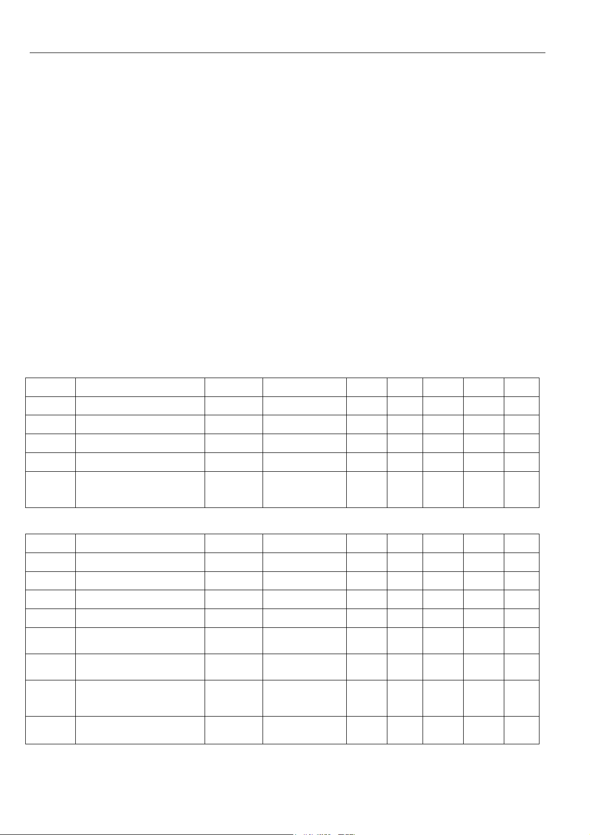
Location
The T6590 Series thermostat is the temperature control
element in the fan-coil or air-conditioning system, and must be
located about 1.2 to 1.5m above the floor (according to local
building regulations) in a position with good air circulation at
room temperature. Do not mount it where it could be affected
by :-
- draughts or dead spots behind doors or in corners
- hot or cold air from ducts
- radiant heat from the sun or appliances
- unheated (uncooled) areas such as an outside wall
behind the thermostat
- concealed pipes or chimneys
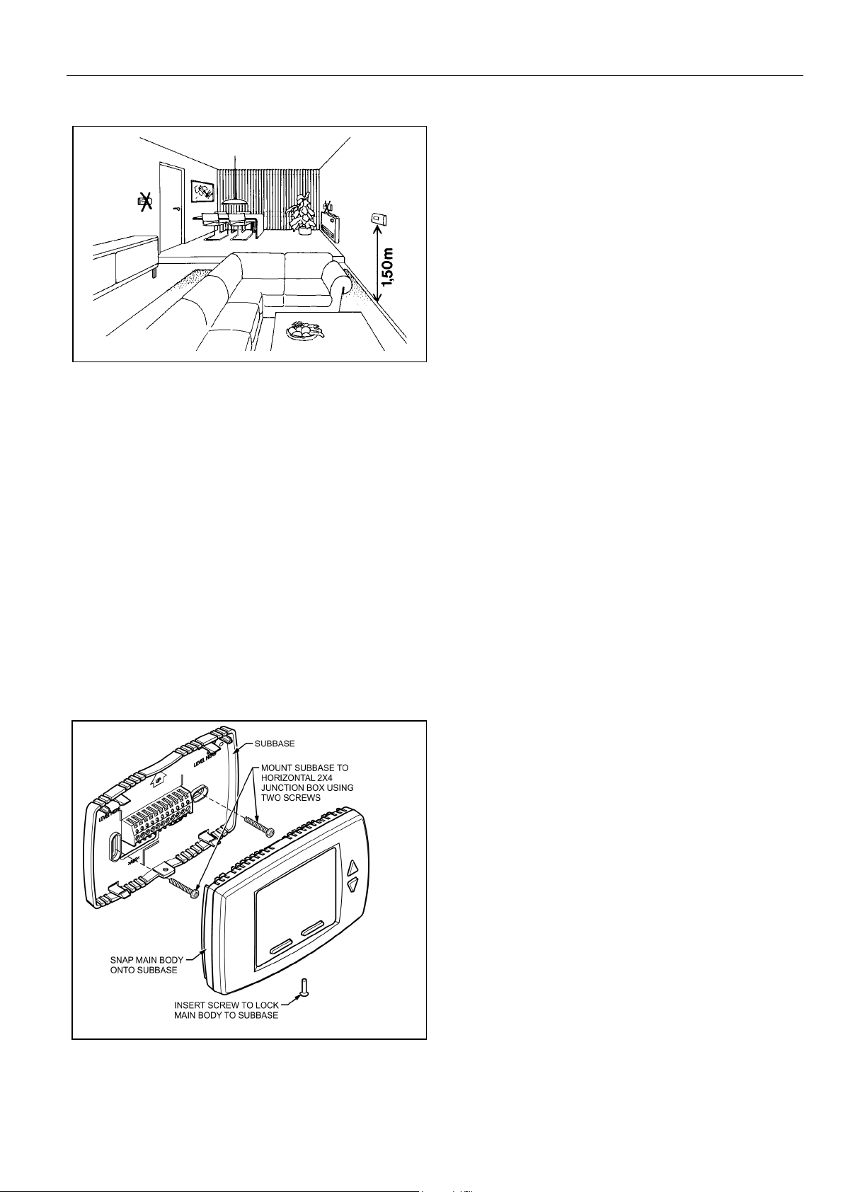
Mounting the thermostat
ny T6590 Series thermostat can be directly mounted on the
wall or horizontally on either a 65x65mm standard junction box
or a 2x4inch US junction box. Mounting screws are supplied for
both alternatives.
IMPORTANT
The installer must be a trained service engineer
Isolate the power supply before beginning installation
T6590 FAN-COIL THERMOSTAT
1. Locate the wall-plate in the mounting position, insert the
mounting screws through the appropriate holes, and
screw into position.
2. Complete the wiring.
3. Attach the thermostat to the wall-plate as follows:
4. Locate the 4 side slots on the wall plate into the
appropriate slots on the back of the thermostat.
5. Press down firmly and snap the thermostat into place.
6. Tighten retaining screw in lower edge of thermostat.
Wiring the thermostat
The standard wiring access is via a hole in the centre of the
thermostat wall-plate.
Removing the thermostat from the wall
If it becomes necessary to remove the thermostat from the
wall-plate:
1. Isolate the power supply before removing the thermostat.
2. Loosen the retaining screw in the lower edge of the
thermostat.
3. Pry the lower edge of the thermostat away from the wallplate.
4. Use both hands to pull the thermostat straight away from
the wall-plate.
5. NOTE - Incorrect removal of the thermostat from the
wall-plate may damage the device.
EN0H8579 R0 2009
3
Page 4

T6590 FAN-COIL THERMOSTAT
)
–
INSTALLER SETUP MODE (ISU
ISU Number and
description
Units Range
- 0 = 2 Pipe system Heat Only
- 1 = 2 Pipe system Cool Only
- 2 = 2 Pipe system 1H1C manual changeover
T6590A1000 & T6590B1000
-
1 System Type
- 4 - 4 pipe system with manual changeover (not available on T6590A1000)
-
- 6 = 2 pipe system 1H1C with Auxiliary Heater. Manual changeover
- 7 = 4 pipe system, mixed manual and automatic changeover (not available on T6590A1000)
-
2 Valve output type
- 1 NC ON/OFF
-
3 Sensor Type
- 1 remote sensor (NTC20K)
-
4 Pipe sensor (Note: This
item will be automatically
populated based on ISU #2
selection).
5 Threshold for pipe sensor
cooling
6 Threshold for pipe sensor
heating
7 Fan control type
-
-
8 Dead band for four pipes ºC
9 Cycles Per Hour (CPH)
value for heating
10 Cycles Per Hour (CPH)
value for cooling
11 Cycles Per Hour (CPH)
value for Auxiliary Heater
-
-
-
-
ºC
ºC
-
-
-
-
3 = 2 Pipe system 1H1C auto changeover (default on T6590A1000)
5 = 4 Pipe system auto changeover (default on T6590B1000) (Not available on T6590A1000)
0 NO ON/OFF (Default)
0 Onboard Sensor (Default)
0 NO input (default mode is Heat)
1 NO input (default mode is Cool)
2 NC input (default mode is Heat)
3 NC input (default mode is Cool)
4 Analog input (Default)(NTC20K, T7414C1012)
Range: 10-18 ºC (Default 15 ºC)
Range: 24-32 ºC (Default 27 ºC)
0 User can choose Cycle or Constant (Default)
(3 speed: Low->Med->High->Auto-> Low)
1 CONSTANT ONLY
(3 speed: Low->Med->High-> Low)
2 CYCLE ONLY
Auto has fan ramping algorithm
1ºC, 2ºC (Default), 3ºC, 4ºC, 5ºC (not available on T6590A1000)
1 – 12CPH (Default 4)
1 – 6CPH (Default 3)
1-12 (Default 6)
N0H8579 R0 2009
Page 5

ISU Number and
description
12 Display
Temperature
adjustment
13 Temperature
Display mode
- 1 display Setpoint
Units Range
ºC -2ºC - +2ºC (Default 0ºC)
- 0 display Room Temperature
T6590 FAN-COIL THERMOSTAT
-
14 Heating setpoint
Range Stops
15 Cooling setpoint
Range Stops
16 Keypad Lockout
- 1 System button Locked out
- 2 Fan and System button Locked out
- 3 All buttons locked out
17 Remote setback
-
-
-
18 Remote setback
heating setpoint
19 Remote setback
cooling setpoint
20 Activity Sensing (No
single key pressed after
certain period which is
configured in this
parameter, the system
will enter unoccupied
mode)
- 1 4 Hour Sensing
ºC
ºC
-
-
ºC
ºC
-
2 display both (Default)
10-32ºC (default 32ºC)
10-32ºC (default 10ºC)
0 All keys available(default)
1: Hotel card NO, with 1 second software delay going from UnOcc to Occupied; 2 minute delay
going from Occupied to UnOcc.
2: Hotel Card NC, with 1 second software delay going from UnOcc to Occupied; 2 minute delay
going from Occupied to UnOcc.
3: Hotel Card enabled, NO, with 1 second software delay going from UnOcc to Occupied; 30 minute
delay going from Occupied to UnOcc
4: Hotel Card enabled, NC, with 1 second software delay going from UnOcc to Occupied; 30 minute
delay going from Occupied to UnOcc.
Range 10-21ºC (Default 18ºC)
Range 22-32ºC (Default 26ºC)
0 Disabled (Default)
- 2 12 Hour Sensing
-
21 Freeze Protection
-
22 Auto Fan Reset
-
-
23 Fan run-on time
after auxiliary heater is
switched off
-
-
S 0 – 600Sec (Default 60Sec)
3 24 Hour Sensing Comment: Anytime the thermostat is not touched (no single key pressed), the
thermostat will automatically fall back into unoccupied setpoints. When any key is pressed,
thermostat controls to occupied mode.
0 Disabled (Default)
1 Enabled – Stat Cycles On Heat when room temperature reaches 4ºC and disables Heat when
room temperature reaches below 8ºC. This feature can not activate if the application is cool only
0 Inactive (Default)
1 Reset back to Auto after 2 hours (Not when constant fan is selected in ISU #7). The start time is
calculated after the initial call for heat/cool.
2 Reset back to Auto after 4 hours (Not allowed when constant fan is selected in ISU #7). The start
time is calculated after the initial call for heat/cool.
5
EN0H8579 R0 2009
Page 6

T6590 FAN-COIL THERMOSTAT
DIMENSIONS
Remote sensor
Remote setback
WIRING DIAGRAMS
Remote sensor
Remote setback
Application 2: Two pipes heating or Cooling, manual
changeover wiring diagram
Remote sensor
Remote setback
Pipe sensor
Application 3: Two pipes, one stage heating or cooling – Auto
changeover wiring diagram
Application 0: Two Pipes, Heating-Only wiring Diagram
N
Remote sensor
Remote setback
Application 1: Two Pipes, Cooling-Only wiring diagram
N0H8579 R0 2009
Remote sensor
Remote setback
Application 4, 5 & 7: Four pipes (Heat + Cool) Manual / Auto
changeover wiring diagram
Page 7

WIRING DIAGRAMS (CONT)
T6590 FAN-COIL THERMOSTAT
Remote sensor
Remote setback
Pipe sensor
Application 6: Two pipe heating or cooling with Auxiliary
electric heater wiring diagram
N
ORDERING SPECIFICATIONS
OS Number Description
T6590A1000
T6590B1000
FCU Controller two pipe,
230VAC
FCU Controller two or four
pipe, 230VAC
Honeywell Control Systems Limited http:/ /europe.hbc.honeywell.com
Newhouse Industrial Estate
Motherwell ML1 5SB
United Kingdom
EN0H8579 R0 2009
7
 Loading...