

Page 1
T6580
FAN COIL CONTROLLER
PRODUCT SPECIFICATION SHEET
30
20
10
DESCRIPTION
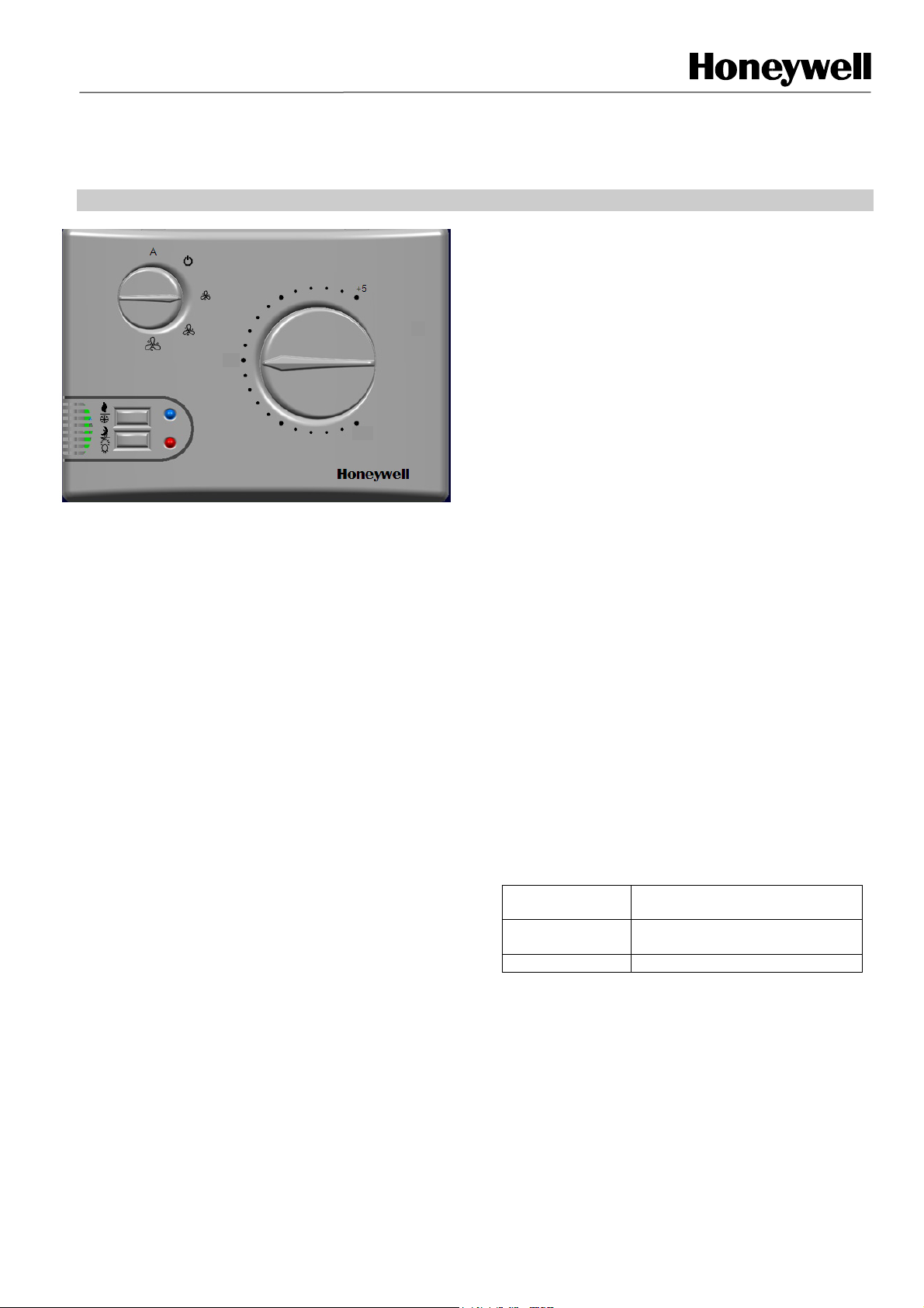
A pleasing and modern appearance makes the T6580 ideal
for living quarter applications, in particular offices and hotels.
In all versions, the control is Proportional + Integral (P+I).
This ensures accurate temperature control in all operating
conditions.
The controller is suitable for mounting on a fan-coil chassis or
for wall mounting.
In 2-pipe plants the summer/winter switching can be activated
by a central contact, controlled automatically through a
connected thermostat or by a sensor installed on the pipe
near the fan coil.
There are two pre-set room regulating levels: Comfort and
Economy, to which two temperature levels are linked; the
selection of which can be made through the room unit or by
digital inputs.
The sensor for the temperature regulation is located inside
the room unit and is overridden if the optional remote sensor
is fitted.
Commands available: set-point configuration knob, fan speed
knob, push button for operating mode setting; push button for
summer/winter switching (Economy mode and summer/winter
switch buttons are not included on the Lite model).
FEATURES
• 2-pipe or 4-pipe fan coil applications
• Installer setup mode allows 11 parameters to be
changed easily on-site
• Proportional + integral digital control regulator
• Heating / cooling sequence and supplementary-
heating with electrical resistance heater
• Electrical resistance / cooling sequence
• Cooling / cooling sequence
• Ventilation only
• Manual or automatic summer / winter switching
• Automatic 3-speed fan control or manual override
• Selectable valve actuators: ON-OFF, PWM
• Actuator voltage: 230 Vac
• Digital inputs: water thermostat, change of season,
economy, window contact
• Analogue inputs: room temperature, inlet water
temperature
• Regulator voltage: 230 Vac, 50/60 Hz
• Destratification cycle
• Filter clean timer
• CE certification
GENERAL INFORMATION
The T6580 microprocessor controls were designed to
regulate heating and/or cooling within a room air-conditioning
systems. The T6580 regulates the water valves, the fan
speed, and the electrical resistance heater (where installed),
in 2-pipe and 4-pipe fan coil systems.
Table 1. Ordering codes for the T6580 FCU Controller:
Model Description
T6580A1008
T6580A1016 LITE FCU Controller 2/4 Pipe
FCU Controller 2/4 Pipe with S/W
switch & Economy function
1 EN0H8560UK07 R0
Page 2

RFC BASIC FAN COIL CONTROLLER
DESCRIPTION
INPUTS AND OUTPUTS
Digital Inputs
PRESENCE or TIMED PROGRAM:
The open contact indicates a presence in the room (room
occupied) and the set point changes from economy to
comfort. This contact can also be linked to an external
timer system.
WINDOW:
The closed contact indicates that the window is open. This
causes the valve(s) to close and the fan to stop (energy
saving function). The anti-freeze protection function is
automatically activated, with 4 °C as default.
SUMMER / WINTER SWITCHING:
A closed contact indicates that warm water is flowing
through the pipes. This automatically changes the control
from summer to winter mode. NB that the water
temperature sensor can also be connected as an
alternative for this feature to operate.
WATER TEMPERATURE THERMOSTAT:
A thermostat can be installed at the water outlet of the heat
exchanger. This thermostat will automatically detect the
presence of warm water in the system during the winter
heating mode. The fan cannot start until warm water is
detected. The temperature of the water must be set on the
thermostat itself.
C) Sensor set to enable both functions: In 2-pipe
systems the sensor detects the supply water temperature
and determines the summer or winter function mode. The
fan function consent during the winter operating mode is
given with a configurable delay time set in Parameter 24.
Analogue and digital outputs
FAN:
Fan speed control, from one to three speeds. A 230 Vac
output, 50 Hz .Max 1.25 (3 peak)A.
HEATING VALVE:
Choice of a 230 Vac, 0.8 A command module for maximum
four on-off or thermal actuators.
COOLING VALVE:
Choice of a 230 Vac, 0.8 A command module for maximum
four on-off or thermal actuators.
Analogue Inputs
RETURN AIR TEMPERATURE SENSOR:
When installed, this sensor has priority over the room unit
internal sensor. The sensor is positioned at the air intake of
the fan coil and is used as alternative to the room sensor.
WATER TEMPERATUR SENSOR:
This sensor can be set to either switch the summer / winter
mode, or to enable fan operation, or both
A) Summer / winter switching: The sensor measures
water supply temperature. When this drops below the limit
value set in Parameter 14, the summer function mode is
activated. When the water supply temperature is above the
limit set in Parameter 15, the winter function mode is
activated. Supply water between the upper and lower limits
means that the thermostat stays OFF.
B) Enabling fan function: In 2 and 4-pipe fan coils the
sensor is installed on the return pipe after the heating coil.
This enables the fan function. Parameters 14 and 15 set
the temperature that enables the fan to start.
2 EN0H8560UK07 R0
Page 3
RFC BASIC FAN COIL CONTROLLER
TECHNICAL FEATURES
BASIC
Regulation range 10…30 °C
Voltage 230 Vac, 50/60 Hz
Outputs (warm and cold
water)
Selector or Keys
Temperature levels Comfort / Economy Pushbutton
Seasons Summer/Winter Pushbutton
Set point Temperature: 10,…30 °C Dial
Analogue Inputs
Room Temperature Air intake probe (remote) NTC10K
Water Temperature Contact or immersion probe NTC10K
Digital Inputs
Window opening
Presence/timed program
Proportional band Selectable from 1 to 5 °C
Dead Zone From 0 to 4 °C
Applications Fan only
2-pipe system with/without electrical
4-pipe system with/without electrical
Housing Single housing
Automatic valve commands
Local Communication No
Centralized Communication No
Table 2. Technical Features
PWM
On-Off
Fan Auto-0-1-2-3
Consent thermostat/summer-winter
switching/anti-condensation pump
resistance
resistance
5-position selector
dial
9
9
9
9
9
9
9
9
9
9
9
9
9
9
9
9
9
9
9
9
9
9
3 EN0H8560UK07 R0
Page 4
RFC BASIC FAN COIL CONTROLLER
FAN FUNCTION
The fan can function provided the consent thermostat is
satisfied or the water temperature probe detects a
temperature above the fixed value, where these inputs are
present.
The fan is controlled through the 5 position-speed selector
dial.
0 = fan OFF. In this position the valve is also closed.
Only the anti-freeze function is activated.
1 = always 1st fan speed
2 = always 2nd fan speed
3 = always 3rd fan speed
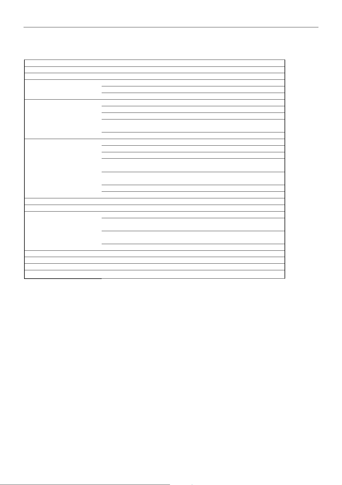
FAN SPEED
3
DEAD BAND
2
1
COOLING PROP. BANDHEATING PROP. BAND
DESTRATIFICATION CYCLE
When the room probe is positioned at the air intake, and
the setpoint is reached, the fan cycles according to the time
settings made in Parameters 20 and 21 to enable correct
reading of the room temperature.
FAN START DELAY DURING THE WINTER
SEASON
During the heating action, the fan switches from OFF to the
first speed, after the delay programmed in Parameter 22.
ELECTRICAL RESISTANCE
When using electrical resistance heater, (i.e., instead of the
water heating system), the fan is started after the delay set in
Parameter 23, starting as soon as the resistance heater was
turned on. When the resistance heater turns off the fan
continues to operate for the time set in Parameter 24.
0
WINTER SETPOINT SUMMER SETPOINT
TEMPERATURE
Fig. 1 Fan speed sequence
In the AUTO function, the fan and the valves are
automatically activated. The fan output varies as a function
of the difference between the room temperature and the set
point.
Auto Position: the fan operates with the speed determined
by the regulator.
In the heating mode, the fan will have speed 0 when Tamb
> (set point ).
1st speed when (set point -30% of the BP) <Tamb < (set
point).The minimum time at this speed is 2 minutes in
normal conditions.
2nd speed when (set point -90% of the BP) <Tamb < (set
point –30% of the BP).The minimum time at this speed is 2
minutes in normal conditions.
3rd speed when Tamb < (set point –90%).The minimum
time at this speed is 2 minutes in normal conditions.
If a variation of more than the BP value occurs between the
set point and the actual temperature, the minimum length
of time in any one state is reduced to 5 seconds.
If the action is cooling, fan control will be opposite to that
used during the heating action.
During the cooling cycle function, and if the set point is
satisfied, the fan will continue to operate at speed 1 for 3
minutes, and will then stop.
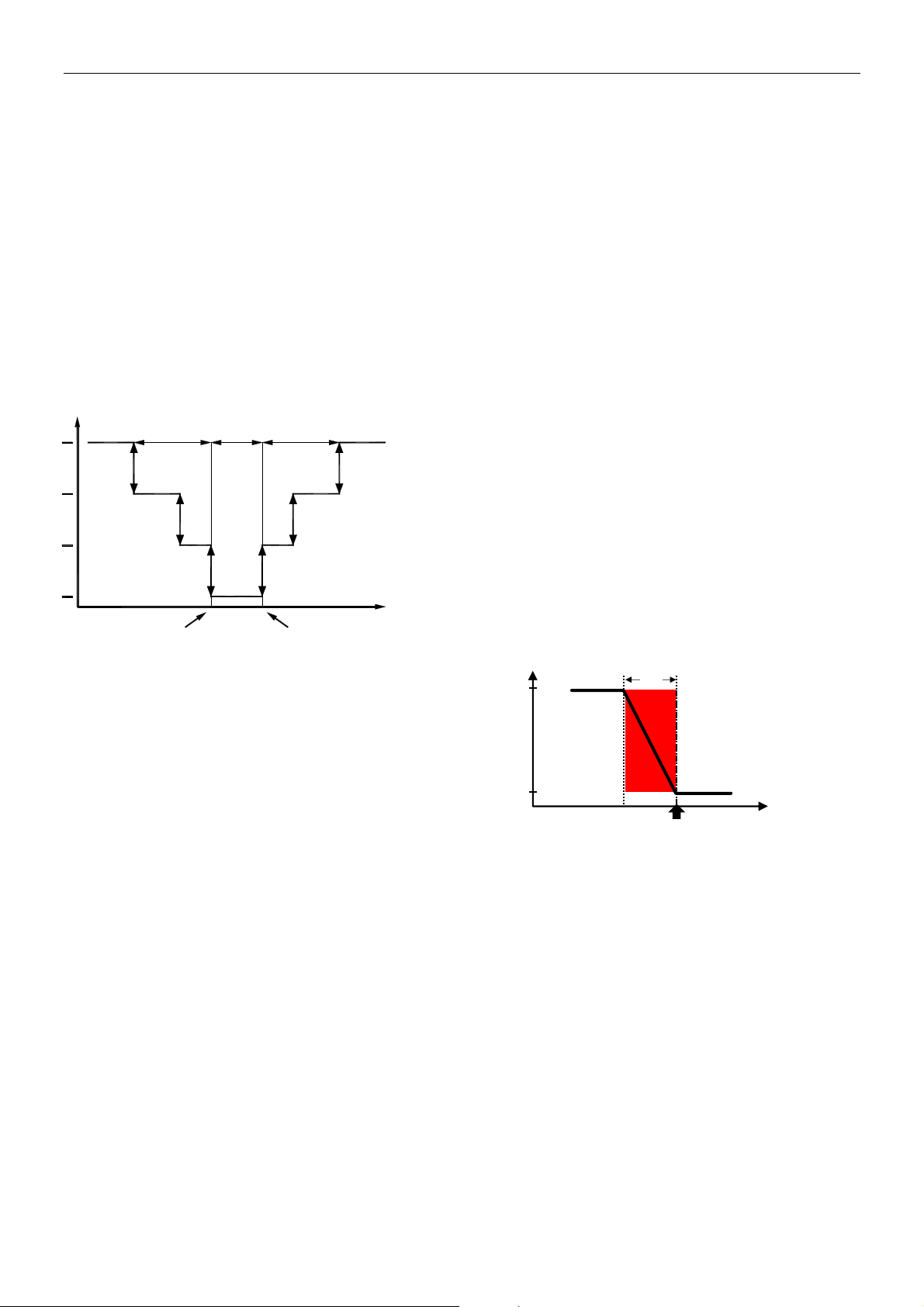
HEATING & COOLING
OUTPUT FUNCTION
Valve Opens
100%
0%
2-PIPE FAN COIL WITH AN ON-OFF and PWM
ACTUATOR:
Fig. 2 :
2-PIPE FAN COIL WITH AN ON-OFF & PWM ACTUATOR
The set point is set to the upper point (to the lower point for
cooling) of the proportional band, so the valve is closed
when the temperature exceeds the set point.
The valve opening percentage is regulated by the P+I algorithm.
X
pH
Set
Temperature (
o
EN0H8560UK07 R0
4
Page 5

RFC BASIC FAN COIL CONTROLLER
4-PIPE FAN COIL WITH ON-OFF & PWM OUTPUT:
Fig. 3
4-PIPE FAN COIL WITH ON-OFF & PWM
Valve Opens
0%
X
pH
ZEB
Set
X
pC
Temperature o C
OUTPUT
The heating set point is set to the upper point, while the
cooling setpoint is set to the heating setpoint plus the dead
band.
The valve opening percentage is regulated by the P+I algorithm.
SIGNALS AND COMMANDS
A
20
30
SEL
2
SEL
3
SEL
1
10
Honeywell
SEL
LED MOD
LED SUMMER/WINTER
LED FILTE
LED MODE
0
E
Fig. 4 Room Unit
The room unit has two signal LEDs that give different
indications during the various operating and configuration
phases.
SUMMER/WINTER LED (BASIC MODEL ONLY):
RED ON when the RFC is in the WINTER function mode.
GREEN ON when the RFC is in the SUMMER function
mode.
RED or GREEN LED BLINKING (1 second ON, 1 second
OFF) when the set point is satisfied, but the fan is still
running, or when the valve is opening and the fan hasn’t
been started yet.
ORANGE LED BLINKING (1 second ON, 5 seconds OFF)
when the room temperature is in the dead band or the set
point is satisfied, since the controller is in the COMFORT
mode.
ORANGE LED BLINKING (1 second ON and 1 second
OFF) in the ECONOMY mode, when the set point is
satisfied.
A
30
20
Honeywell
R
10
ORANGE LED BLINKING (1 second ON and 15 seconds
OFF) in the OFF state.
MODE LED:
Function mode display
The flashing of the Mode LED shows the current state of
the regulator (COMFORT or ECONOMY).
When pressing the SEL 3 key, the changes to the flashing
of the Mode LED indicates the state of the device. In
particular:
With the controller in COMFORT mode: when pressing the
SEL 3 key the Mode LED turns on.
With the controller in the ECONOMY mode: when pressing
the SEL 3 key the Mode LED flashes regularly 3 times a
second.
Dirty Filter Signal and Alarm
With the controller in normal operating mode the
Mode LED turns on
have been reached.
This signal indicates that the filter must be cleaned.
After cleaning the filter, proceed as described below to
reset the operating hours count down:
1. Press the SEL3 knob until the Mode LED briefly
blinks 8 times. The filter operating hours are then
reset to zero.
when the filter maintenance hours
Daily valve drive
SEL
SEL
To prevent a possible valve blockage due to a prolonged
0
standstill period, the valve is driven automatically at least
2
once every 24 hours for 150 seconds. This function is
enabled by parameter 19.
CHANGE OF THE ROOM UNIT
FUNCTION MODES
FOR ROOM UNITS WITHOUT A DISPLAY
CHANGE OF SEASON – SUMMER / WINTER
(BASIC MODEL ONLY)
If Parameter #9 (summer / winter switching) is in the
MANUAL mode, changing the season is possible by using
the SEL1 KEY on the front panel. Press this key for 5
seconds until the colour of the selected season appears on
the S/W LED for 5 seconds. After this, the LED will assume
the appropriate operating mode. The default value of
Parameter #9 is Manual.
CHANGE OF FUNCTION MODE (COMFORT /
ECONOMY)
During normal functioning, while the unit is turned ON, it is
possible to change the operating mode mode, from
COMFORT to ECONOMY, in succession by using SEL3.
Proceed as follows:
In the COMFORT mode: when pressing the SEL3 key, the
Mode LED turns on and stays on (comfort). By continuing
5 EN0H8560UK07 R0
Page 6

RFC BASIC FAN COIL CONTROLLER
to press the key, the controller switches to the ECONOMY
mode after 5 seconds and the Mode LED blinks for 0,3
seconds ON - 0,3 seconds OFF until the key is released.
From the ECONOMY mode: if the SEL3 key is pressed
again, the Mode LED blinks for 0,3 seconds ON - 0,3
seconds OFF. By continuing to press the key for another 5
seconds the controller switches to the COMFORT mode,
and the Mode LED will turn to on and stay on.
INSTALLATION
POSITION
The RFC series room unit is the room temperature control
element in a fan coil plant, or small split system units. The
room probe of the unit must be positioned 1.5 m from the
floor (according to local legislation, this may be 1.2m), in a
position exposed to good room air circulation. It should not
be affected by:
Fig. 5 Positioning the room unit
INSTALLATION
IMPORTANT: this product must be installed according to
the local safety norms in force and only by qualified
personnel. Isolate the electrical power supply before
starting to install or dismantle the device.
INSTALLING THE ROOM UNIT
a. Air currents or dead zones behind doors or in
corners
b. Warm or cold air coming from air ducts
c. Solar radiation or radiation from household
appliances
d. Non heated or cooled areas such as external walls
behind the room unit
e. Pipes or chimneys embedded in the wall
1. Using a screwdriver, loosen the retaining screw in
the bottom side of the housing, until the cover can
be removed.
2. Pass the wires to rear holes of housing and then
fix to the wall with screws.
3. Fix the wires to the connector, taking care to
follow the electrical diagram.
4. Replace the cover and secure it by tightening the
screw in the bottom part of the housing.
TO
THE
WALL
C
WALL
FIXING
HOLES
A
B
A
30
20
10
Honeywell
Fig. 6
Installing the wall-mount room unit
INSTALLING THE SENSORS:
1. Water Temperature sensor for automatic
Summer/Winter switching: position the sensor
upstream from the valve as shown in Fig. 7.
2. Water Temperature sensor for automatic
Summer/Winter switching and fan start
consent thermostat: position the sensor as
shown in Fig. 7.
3. Temperature sensor with fan start consent
thermostat function: position the sensor on the
exchanger fins as shown in Fig. 8.
Fan Coil System
Fig. 7 Locating the Summer / Winter water sensor
EN0H8560UK07 R0
6
Page 7

RFC BASIC FAN COIL CONTROLLER
Exchanger Fins
Fig. 8 Locating the Fan Coil consent water sensor
WIRING THE REGULATOR
2
The terminals are suitable for 1.5 mm
cables.
WIRING THE ACTUATORS FOR 4-PIPE SYSTEMS
The actuators must be wired to terminals 4-3 (heating
water valve) and 4-2 (cooling water valve).
WIRING THE ACTUATORS FOR 2-PIPE SYSTEMS
In 2-pipe fan coil systems, the actuator must be connected
to the heating water outlet, terminals 4, 3.
STARTUP
MANUAL PARAMETER SETUP PROCEDURE
The RFC regulator allows manual access to the
parameters without the need of a PC.
SEL
2
SEL
3
SEL
1
Fig. 9
Setting the parameters
The SEL0 selector knob allows parameters (from 1 to 10)
to be selected, (see parameter table below).
The fan speed selector SEL2 allows the value of the
chosen parameter to be set.
The SEL1 and SEL3 keys, if pressed simultaneously for 5
seconds, allow access to the “parameter settings mode”.
A
30
20
10
Honeywell
SEL
0
LED MOD
LED SUMMER/WINTER
LED FILTE
LED MODE
E
R
SEL1 is used as the “Enter” button when pressed during
the programming phase and confirms the newly set value.
If pressed for 5 seconds during programming, SEL1 saves
the parameter settings (the green S/W LED blinks 3 times
to indicate that the data has been saved).
The green or red LED indicates which value was set in the
parameter selected by the “selector SEL 0” knob.
SETTING OR CHANGING THE PARAMETER
VALUES
To access the “parameter setting” mode, proceed as
follows:
1) Rotate and set the SEL0 knob to position 10 degrees.
2) Set the SEL2 knob to the AUTO position.
3) Press keys SEL1 and SEL3 for >= 5 sec.
After pressing the keys for 5 seconds, the S/W LED will
start to blink alternating red-green-red-green for 3 seconds
to indicate that the “parameter setting” mode Has been
accessed.
Three seconds after accessing the ‘parameter selection
menu’, the LED turns to green if the current parameter
corresponds to the value selected with the SEL0 knob.
The LED turns red if the current parameter is not the
selected one.
To change a parameter value, position the SEL2 knob to
the selected value (the LED will turn red), then press the
SEL1 programming key and wait until the LED turns to
green.
To save a new setting in the permanent memory of the
controller, press the SEL1 key for >= 5 seconds; the green
LED will blink 3 times to confirm the new parameter
settings.
After saving the value, the controller immediately exits the
parameter configuration mode.
The above sequence is valid for the configuration of all
parameters that are selectable with the SEL0 knob,
therefore:
Select a parameter by rotating the SEL0 knob, and set its
value with the selector knob SEL2.
CHECKING THE PARAMETER SETTINGS
By simply moving selector knob SEL2 one can also check
which value was set in any specific parameter (green LED
= the same chosen parameter, red LED = a different
parameter). If no controls are touched for two minutes, the
controller will revert to normal operating mode.
RESETTING TO THE DEFAULT VALUES
1. Set the SEL0 knob to + 10 °C.
2. Set the SEL2 knob to position 2.
3. The red LED blinks quickly to indicate that the
default parameter table has been chosen.
4. Press the programming key SEL1.
5. The GREEN LED on the device blinks 3 times to
indicate that the device is saving the DEFAULT
parameter table.
7 EN0H8560UK07 R0
Page 8

RFC BASIC FAN COIL CONTROLLER
st
1
LEVEL PARAMETER TABLE
The parameters below are the ones that can be directly modified from the controller key pad.
SEL0
KNOB
POSITIO
N
10 1
11 2 DEAD BAND
12 3
13 4
14 5
15 6
16 7
17 8
18 9
19 10
20 11
PARAMETER
No.
TO BE SET
PARAMETER
COMFORT
SET POINT
RANGE
TYPE OF
PLANT
TYPE OF
OUTPUT
WINDOW
CONTACT
DESTRATIFIC
ATION
WATER
TEMPERATUR
E SENSOR
FUNCTION
SUMMER /
WINTER
SWITCHING
SENSOR
READING
OFFSET
RESET
FAN
Selector Position
PARAMETER
DESCRIPTION
DEFAULT VALUE
Configuring the
COMFORT
set point range
Defines the Dead
Band
by 4-pipe plants
Type of plant 2-PIPE 4-PIPE FAN ONLY
Defines the fan
operating
mode in the dead
band
Defines the type of
regulation at output 1
Defines if the window
contact is n. o. or n. c.
Activate or deactivate
the destratification
function
Selecting the NTC
probe function for the
water temperature
Selecting summer
to winter switching
Modifies the room
temperature sensor
reading
Resetting the
DEFAULT
values or the Filter
hours
10-30 12-28 13-27 14-26 15-25
CONTINUOUSLY
FAN FUNCTION
SEL 1
AUTO
4 3 2 1 0
CYCLED CONTINUOUS
PWM ON-OFF
ACTIVE =
CLOSED
ENABLED DISABLED
CONSENT
Manual
0 + 1°C - 1°C + 2°C - 2°C
Selector
Position
SEL 1
OFF
ACTIVE =
CONTINUOUSL
YOPEN
SUMMER /
WINTER
SWITCHING
Centralized
or by
NTC probe
Setting the filter
hours to zero
Selector
Position
SEL 1
1
CYCLED IN
WINTER /
CONTINUOUS
IN SUMMER
WITHOUT
PROBE
From the room
unit
Selector
Position
SEL 1
CYCLED
SUMMER /
CONTINUO
US IN
WINTER
SUMMER /
WINTER
SWITCHIN
+ FAN
FUNCTION
CONSENT
Resetting
the default
parameters
Other parameters that are listed in the following table can be modified with factory software, though the TTL port.
Selector
Position
2
IN
G
SEL 1
3
EN0H8560UK07 R0
8
Page 9

RFC BASIC FAN COIL CONTROLLER
nd
2
LEVEL PARAMETER TABLE
PARAMETER
No
12
13
14
15
16
17 Dirty filter signal Parameter K value 0 0 (disabled) 1 – 20 K x300 HH
18 NOT AVAILABLE
19 Valve exercise
20
21
22
23
24
PARAMETER TO
BE
CONFIGURED
Proportional band
°C
Economy set point
variation
Winter
temperature
function consent
Summer
temperature
function consent
Anti-freeze
protection °C
De-stratification,
maximum
fan OFF time
(minutes)
De-stratification,
minimum
fan ON time
(minutes)
Fan start delay
(seconds)
Fan start through
electrical
resistance
(seconds)
Fan stop through
electrical
resistance
(seconds)
PARAMETER DESCRIPTION DEFAULT VALUE RANGE NOTES
Defines the temperature range in which
the P+I regulation is carried out
Defines the value to be added to the summer
set point and subtracted from the winter set
point
when the room is not occupied
This parameter defines the water
temperature
above which the system switches to the
winter mode or enables the fan
This parameter defines the water
temperature
below which the system switches to the
summer mode or enables the fan
Room temperature value, below which
the anti-freeze function is activated
Enables or disables a periodic valve
activation to avoid valve blockage
Defines the fan disabling time
during the de-stratification process
Defines the fan enabling time
during the de-stratification process
The fan start delay with respect to
the heating output activation time
Defines the time delay between the electrical
heater switching on and the fan starting
Defines the time that the fan overruns after
the electrical heater is switched off
2 1-5
2 5-10
38 20-60
14 5 - 25
4 0 - 10 °C
Disabled
15 1 – 60
1 1-10
120 0 – 250
30 0-250
60 0-250
• Disabled
• Enabled
9 EN0H8560UK07 R0
Page 10

RFC BASIC FAN COIL CONTROLLER
ELECTRICAL CONNECTIONS
L
1
2
3
EN0H8560UK07 R0
10
Page 11

RFC BASIC FAN COIL CONTROLLER
,
DIMENSIONS
A
20
30
10
Honeywell
The T6580 product family and its associated documentation and packaging are protected by various intellectual property rights belonging to
Honeywell Inc and its subsidiaries and existing under the laws of the UK and other countries. These intellectual and property rights may include
patent applications, registered designs, unregistered designs, registered trade marks, unregistered trade marks and copyrights.
Honeywell reserves the right to modify this document, product and functionality without notice. This document replaces any previously issued
instructions and is only applicable to the product(s) described.
This product has been designed for applications as described within this document. For use outside of the scope as described herein, refer to
Honeywell for guidance. Honeywell cannot be held responsible for misapplication of the product(s) described within this document.
Manufactured in the UK, for, and on behalf of the Environment and Combustion Controls Division of Honeywell Technologies Sàrl, ACS-ECC
EMEA
Z.A. La Pièce 16, 1180 Rolle, Switzerland by its Authorised Representative Honeywell Inc.
Honeywell Control Systems Ltd.
Newhouse Industrial Estate,
Motherwell ML1 5SB,
United Kingdom
http://europe.hbc.honeywell.com EN0H8560UK07 R0
 Loading...