

Page 1
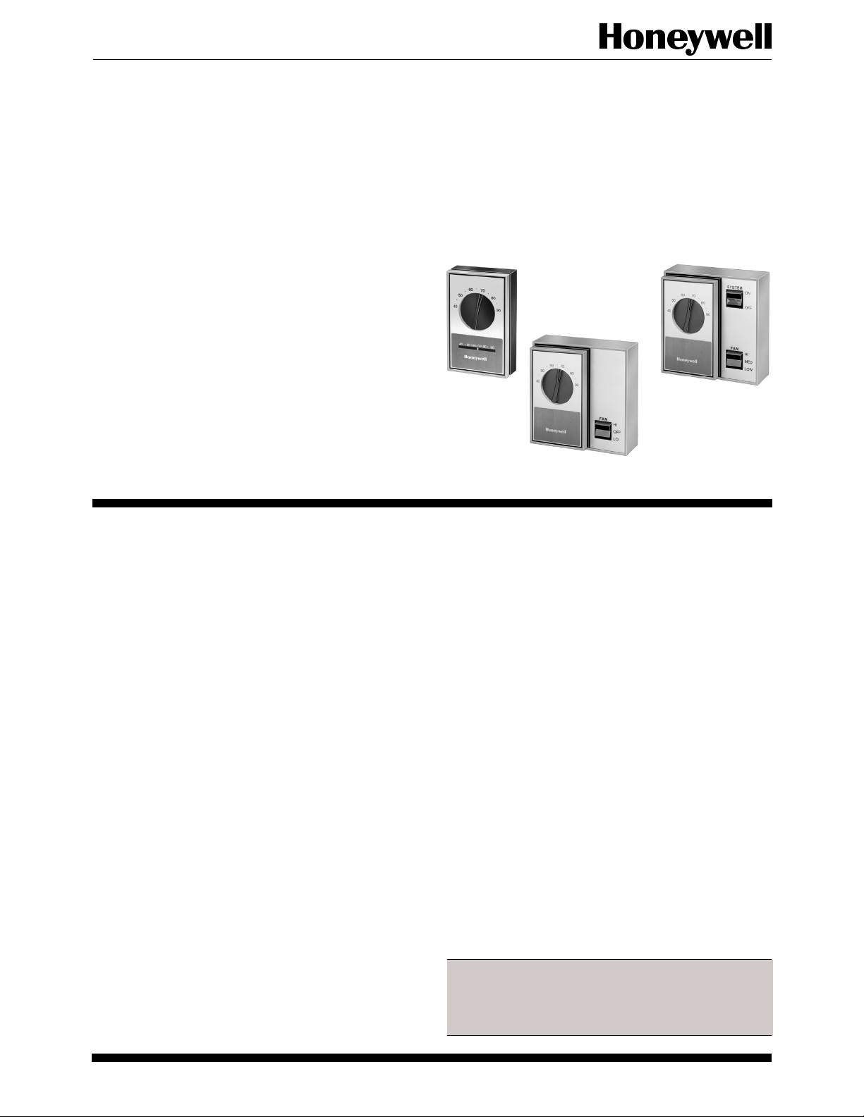
T451A, T651A, T694A,B,D,F
Line Voltage Thermostats
T451, T651, T694 Thermostats provide on-off
control of valves, fans, motors, contactors, electric
heat elements, duct furnaces and fan coil units in
heating/cooling systems. Switching subbases provide manual control of heating, cooling and fan.
Light Duty
■ T451A provides heating control only.
■ T651A provides heating and cooling control.
■ T694A,B,D,F supplied with switching subbase to pro-
vide manual control of heating, cooling and fan.
■ Q473A,B switching subbase available for T451A/
T651A.
■ Automatic cooling anticipator for 120, 208, 240 and
277 Vac.
T451A,
T651A
T694A
■ Thermostats use spst or spdt snap switches activated
by bimetal sensor.
■ T451A/T651A mount on standard vertical or horizontal junction box.
■ Options include adjustable range stops, locking cover,
concealed setpoint, locking setpoint, positive off control, cover thermometer.
T694B,D,F
CONTENTS
Specifications ................................................. 2
Ordering Information..................................... 2
Installation ..................................................... 4
Checkout......................................................... 7
1 63-2051—4J. H. • Rev. 9-92 • ©Honeywell Inc. 1992 • Form Number 63-2051—4
Page 2
T451A, T651A, T694A,B,D,F
SPECIFICATIONS • ORDERING INFORMATION
Specifications
SUPER TRADELINE MODEL
TRADELINE models are selected and packaged to provide
ease of stocking, ease of handling and maximum replacement value. TRADELINE model specifications are the
same as those of standard models except as noted below.
SUPER TRADELINE MODEL AVAILABLE:
T651A2028 Light Duty Line Voltage Thermostat.
FEATURES:
— Temperature scale range 35° F to 95° F.
— Spdt switch breaks heating contacts and makes cooling
contacts on temperature rise.
— Automatic cooling anticipator for 120, 208, 240 and
277 Vac.
— Vertical faceplate with Fahrenheit scale and ther-
mometer.
— Horizontal faceplate with Fahrenheit scale and ther-
mometer.
—Blank vertical faceplate.
—Blank horizontal faceplate.
— Wallplate.
— Adjustable range stops.
— Locking cover screw.
STANDARD MODELS:
Model Changeover
Number Application System Switch Switch Fan Switch
T451A2007aHeating only. — — —
T451A2015 Heating only with positive OFF. — — —
T651A2028aHeating/cooling. — — —
T694A2002 Heating/cooling. OFF position breaks ON-OFF — HI-MEDIUM-LO
fan circuit.
T694B2001 Heating/cooling. OFF position breaks ON-OFF HEAT-COOL HI-MEDIUM-LO
cooling and fan circuits.
T694D2009 Heating/cooling. Heating circuits isolated ON-OFF HEAT-COOL HI-MEDIUM-LO
from cooling circuits. OFF position
breaks all control circuits except heat.
T694F2007 Heating/cooling. Heating circuits isolated ON-OFF HEAT-COOL HI-MEDIUM-LO
from cooling circuits. OFF position breaks
all power to fan and thermostat.
a
With thermometer.
Ordering Information
When purchasing replacement and modernization products from your TRADELINE® wholesaler or your distributor, refer to the
TRADELINE Catalog or price sheets for complete ordering number, or specify—
1. Order number.
2. Accessories, if desired.
3. Order additional components and system accessories separately.
If you have additional questions, need further information, or would like to comment on our products or services, please write or phone:
1. Your local Honeywell Home and Building Control Sales Office (check white pages of your phone directory).
2. Home and Building Control Customer Satisfaction
Honeywell Inc., 1885 Douglas Drive North
Golden Valley, MN 55422-4386 (612) 951-1000
In Canada—Honeywell Limited/Honeywell Limitee, 740 Ellesmere Road, Scarborough, Ontario M1P 2V9, International Sales and
Service offices in all principal cities of the world. Manufacturing in Australia, Canada, Finland, France, Germany, Japan, Mexico,
Netherlands, Spain, Taiwan, United Kingdom, U.S.A.
2
Page 3
T451A, T651A, T694A,B,D,F
[48]
SPECIFICATIONS
ELECTRICAL RATINGS (A):
Voltage (Vac)
120 208/240/277
Full Load 8 4
a
Locked Rotor 48 24
a
Wider temperature differential ranges can occur when
used in cooling applications with current draws that are
more than four amps. If a wider differential range is
unacceptable, use a T6051 Heavy Duty Line Voltage
Thermostat for a smaller differential range.
Pilot Duty: 125 VA.
7.2A Resistive: heating contacts only.
TEMPERATURE SETTING RANGE: 35° F to 95° F [2° C
to 35° C] (with range stops removed).
STORAGE TEMPERATURE: -40° F to 150° F [-40° C to
66° C].
FIXED DIFFERENTIAL: 2° F [1° C].
SWITCHING ACTION:
T451: Spst. Contacts make on temperature fall.
T651: Spdt. Heating contacts break and cooling contacts
make on temperature rise.
T694: Spdt. Heating contacts break and cooling contacts
make on temperature rise.
FIELD WIRING CONNECTIONS: No. 10 screw terminals
on T451A/T651A; color-coded leads on T694 models.
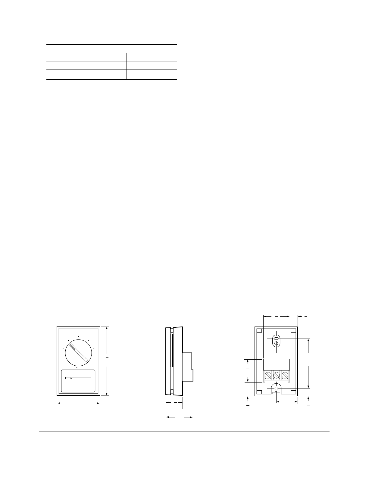
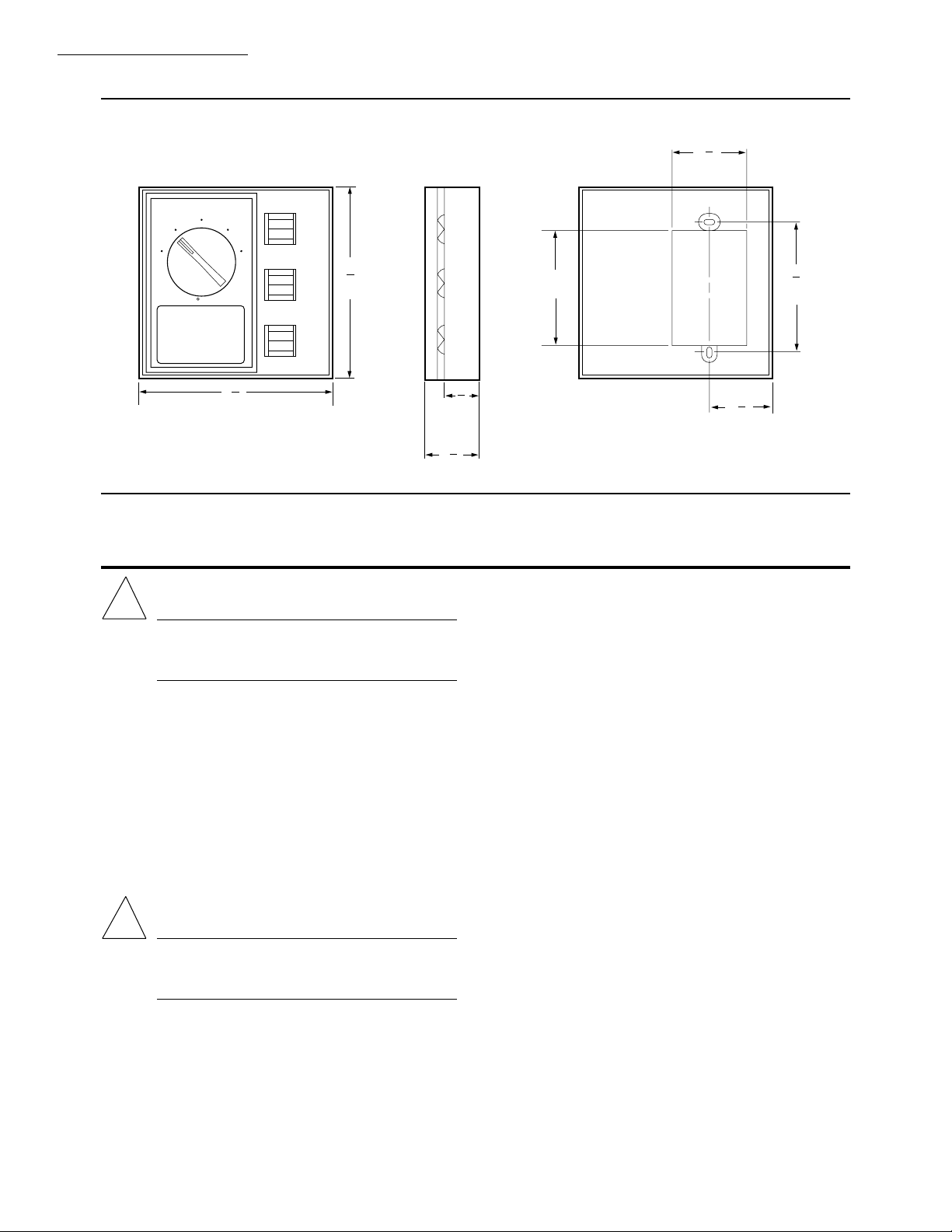
DIMENSIONS: See Figs. 1 and 2.
FINISH: Brushed champagne gold and dark pewter face-
plate; beige and brown case.
UNDERWRITERS LABORATORIES INC.: Listed.
ACCESSORIES:
Q473A2006 Switching Subbase: Use with T651A for
HEAT-OFF-COOL manual system switching.
Q473B2005 Switching Subbase: Use with T451A/
T652A for AUTO/OFF switching in heating only or
cooling only applications.
220124A Faceplate vertical, Fahrenheit scale, with
thermometer.
a
220124B Faceplate vertical, Celsius scale, with ther-
mometer.
220124C Faceplate, horizontal, Fahrenheit scale, with
thermometer.
a
220124D Faceplate, horizontal, Celsius scale, with ther-
mometer.
220125A Faceplate, horizontal, Fahrenheit scale, with-
out thermometer.
220125B Faceplate, vertical, Fahrenheit scale, without
thermometer.
220125C Faceplate, horizontal, Celsius scale, without
thermometer.
220125D Faceplate, vertical, Celsius scale, without ther-
mometer.
220126A Faceplate, horizontal, blank (concealed setpoint,
without thermometer).
220126B Faceplate, vertical, blank (concealed setpoint,
without thermometer).
220213 Wallplate, covers old T451A/T651A wall marks
when installing new T451A/T651A.
a
a
a
199242 Wallplate, covers old T694 wall marks when
installing new T694.
Fig. 1—T451A, T651A mounting dimensions in in. [mm].
70
60
50
40
40 50 60 70 80 90
80
90
17
4
32
F
13
2
16
[70]
[114]
1
[22]
1
8
13
1
16
a
Supplied with SUPER TRADELINE model T651A.
1
[45]
15
16
[24]
3
4
15
1
32
[35]
COOL HEAT COM
1
[37]
9
16
[14]
3
[83]
1
8
[14]
M6130
9
32
17
32
3 63-2051—4
Page 4
T451A, T651A, T694A,B,D,F
[36]
!
!
INSTALLATION
Fig. 2—T694A,B,D,F mounting dimensions in in. [mm].
70
60
50
40
80
F
7
1
8
[48]
SYSTEM
ON
OFF
90
HEAT
COOL
FAN
MED
LOW
7
4
8
[124]
HI
[76]
3
9
3
32
[83]
29
4
32
[125 ]
(T694B SHOWN)
1
WARNING
Do not use on electric heat. Possible fire hazard if
T694A,B,D used on electric heat. T694F can be
used on electric heat.
WHEN INSTALLING THIS PRODUCT…
1. Read these instructions carefully. Failure to follow
them could damage the product or cause a hazardous
condition.
2. Check the ratings given in the instructions and on
the product to make sure the product is suitable for your
application.
3. Installer must be a trained, experienced service
technician.
4. After installation is complete, check out product op-
eration as provided in these instructions.
CAUTION
Disconnect power supply before making wiring
connections to prevent electrical shock and equipment damage. Use copper wire only.
LOCATION
Select the same location as control to be replaced, or
select a new location about 5 ft. [1.5 m] above the floor, on
an inside wall where there is good air circulation at average
room temperature.
15
13
32
[35]
32
9
1
16
[40]
Installation
Do not install the thermostat where it may be affected by:
•drafts, or dead spots behind doors and in corners.
• hot or cold air from ducts.
•radiant heat from sun or appliances.
• concealed pipes and chimneys.
• unheated (uncooled) areas behind the thermostat,
such as an outside wall.
WIRING AND MOUNTING
Disconnect power supply before making wiring connections to prevent electrical shock and equipment damage.
All wiring must comply with applicable electrical codes,
ordinances and regulations. Use copper wire only. Make
sure that thermostat electrical rating is sufficient for current
requirements of controlled equipment, and that listed voltage matches power supply.
T451A/T651A THERMOSTATS (Fig. 3)
T451A/T651A Thermostats mount vertically on a 2 x 4
in. or 4 x 4 in. junction box. See Fig. 3. Use 2 x 4 in. cover
plate with 4 x 4 in. junction. For horizontal mounting, the
appropriate horizontal faceplate is required. Horizontal
with thermometer and horizontal blank faceplates are
packaged with the T651A2028 SUPER TRADELINE
model. For additional faceplates or T451 applications, see
Accessories. When replacing old style T451A/T651A, use
a wallplate to cover previous wall marks. This wallplate is
packaged with the T651A2028 SUPER TRADELINE
model. For T451 applications, see Accessories.
M6129
4
Page 5

T451A, T651A, T694A,B,D,F
INSTALLATION
1. Before mounting thermostat, connect system wiring
to proper terminals at rear of thermostat. Follow equipment manufacturer instructions or refer to Fig. 4 for
typical system hookup.
2. Remove cover assembly from thermostat. Attach
thermostat to junction box with two screws provided. Replace cover assembly. See Fig. 3.
3. Use 1/16 hex Allen wrench to install Allen locking
cover screw.
Fig. 3—Mounting T451A/T651A.
220213 WALLPLATE
ACCESSORY
(OPTIONAL)
(COVERS OLD T651A
WALL MARKS WHEN
INSTALLING NEW T651A)
2. Remove thermostat cover assembly. Attach thermostat to junction box with two screws provided. Replace
thermostat cover assembly.
Fig. 4—T652A in heating-cooling system.
Fig. 5—Mounting T694A,B,D,F.
TABS HOLD
COVER ASSEMBLY
AT TOP (SNAP
IN AT BOTTOM)
MOUNTING
SCREWS (2)
70
80
60
90
USE 2x4
JUNCTION
BOX
M6131
50
40
40 50 60 70 80 90
F
T694A,B,D,F THERMOSTATS (Fig. 5)
All T694A,B,D,F Thermostats mount vertically on a 2 x
4 in. or 4 x 4 in. junction box. See Fig. 5. Use 2 x 4 in. cover
plate with 4 x 4 in. junction box.
1. Before mounting, connect system wiring to proper
color-coded leads at rear of thermostat. Follow equipment
manufacturer instructions or refer to Figs. 6-9 for typical
system hookups.
4x4 JUNCTION
BOX
USE 2x4 OR 4x4
JUNCTION BOX
M6135
(T694B SHOWN)
TABS HOLD
COVER ASSEMBLY
AT TOP (SNAP
IN AT BOTTOM)
ON
SYSTEM
OFF
HEAT
COOL
HI
FAN
MED
LOW
COVER PLATE
MOUNTING
SCREWS (2)
70
60
50
40
F
80
90
5 63-2051—4
Page 6

T451A, T651A, T694A,B,D,F
INSTALLATION
Fig. 6—T694A in heating-cooling system with
independent valve and fan circuits.
Fig. 8—T694D with isolated switching for heating
and cooling.
Fig. 7—T694B connected for positive-off switching in COOL position.
Fig. 9—T694F with positive-off position.
6
Page 7

T451A, T651A, T694A,B,D,F
CHECKOUT
Checkout
After the thermostat is wired and mounted, perform the
following system checkout procedure.
T451/T651
IN HEATING APPLICATION:
1. Close disconnect switch (if used).
2. Adjust setpoint above room temperature and check
that heating system turns on.
3. Adjust setpoint below room temperature and check
that heating system turns off.
4. Adjust thermostat for desired room temperature.
IN COOLING APPLICATION:
1. Close disconnect switch (if used).
2. Adjust setpoint below room temperature and check
that cooling system turns on.
3. Adjust setpoint above from temperature and check
that cooling system turns off.
4. Adjust thermostat for desired room temperature.
NOTE: Wider temperature differential ranges can occur
when used in cooling applications with current draws
that are more than four amps. If a wider differential
range is unacceptable, use a T6051 Heavy Duty Line
Voltage Thermostat for a smaller differential range.
T694
NOTE: System switch must be in ON position to check
out system.
1. Close the disconnect switch (if used) and press
HEAT switch; adjust setpoint above room temperature
and check that heating system turns on.
2. Adjust setpoint below room temperature and check
that heating system turns off.
3. Press COOL switch; adjust setpoint below room
temperature. Check that cooling system turns on and fan
runs continuously.
4. Press fan LO, MED, HI switches and check that fan
control operates properly.
5. Adjust setpoint above room temperature and check
that cooling system turns off. Fan operates continuously.
6. Adjust thermostat for desired room temperature.
If questions arise regarding this product, contact your
distributor or local Honeywell representative.
7 63-2051—4
Page 8

Home and Building Control Home and Building Control Helping You Control Your World
Honeywell Inc. Honeywell Limited—Honeywell Limitée
1985 Douglas Drive North 740 Ellesmere Road
Golden Valley, MN 55422 Scarborough, Ontario
Printed in U.S.A.
M1P 2V9
8
QUALITY IS
KEY
 Loading...