

Page 1
T641A,B,C
Floating Control Thermostats
Installation instructions for the trained service technician.
Application
The T641A,B,C Floating Control Thermostats provide
spdt outputs to control floating actuators in applications
such as variable air volume (VAV) terminal units.
—T641A: standard spdt floating control thermostat.
—T641B: incorporates momentary system override switch
to provide external relay connection to be energized for
override in building management systems or other
applications.
—T641C: provides manual heat/cool changeover switch.
Operation
FLOATING CONTROL
The control provided by the T641 is conventionally
termed floating control. During floating control, a variation
of two-position control, the thermostat provides a three
output control, Advance motor, Reverse motor, and Hold.
On a change in temperature, the T641 drives the actuator
to an intermediate position and then opens the circuit to the
actuator. The actuator remains in this position until there is a
temperature change at the T641. The actuator is said to float
between the limits of the T641 to satisfy various load requirements. See Fig. 1.
VAV SYSTEMS
VAV systems control the temperature within a space by
varying the volume of supply air. Air is delivered to the space
at a fixed temperature. The volume of supply air is controlled
by the space thermostat modulating the supply air damper.
When full heating and cooling flexibility is required in a zone,
it is handled by perimeter heating, or reheat capability in the
air terminal units. As individual zones shut down, the total air
flow in the system is regulated by a central duct static pressure
controller. The fan system is sized to handle an average peak
load, not the sum of the individual peaks. As each zone peaks
at a different time of day, extra air is borrowed from the offpeak zones. This transfer from low-load to high-load zones
occurs only in true VAV systems.
Pressure dependent systems do not incorporate an individual zone air flow sensor and depend on a stable system
pressure to maintain flow. These systems require slower
motors such as the seven minute ML6161 models that are
typically controlled by the T641 thermostats.
HEAT ANTICIPATION/COOL ANTICIPATION
Control of heating or cooling units with a thermostat does
not allow for the temperature to remain exactly at the thermostat set point, but varies within a certain temperature range.
Anticipation is added to the thermostat to reduce this range.
The anticipator is a small resistive heater in the thermo-
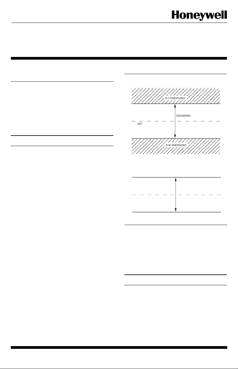
Fig. 1—T641 floating control.
R-Y ENERGIZED
DEADBAND
SET POINT
R-W ENERGIZED
FOR EXAMPLE, WITH SET POINT = 70°F
R-Y SWITCH WILL ENERGIZE AT 71.5°F
R-W SWITCH WILL ENERGIZE AT 68.5°F
71.5°F
SET POINT 70°F
68.5°F
stat which heats when the system is on or off. The heat
produced by the anticipator raises the internal bimetal temperature slightly faster than the surrounding room temperature. The thermostat anticipates the need to shut off the
heating system sooner than it would if affected by room
temperature only. The T641 has fixed or voltage anticipation.
R-Y ENERGIZED
3° DEADBAND
R-W ENERGIZED
M2283
Installation
WHEN INSTALLING THIS PRODUCT…
1. Read these instructions carefully. Failure to follow
them could cause a hazardous condition.
2. Check the ratings given in the instructions and on the
product to make sure the product is suitable for your application.
3. Installer must be a trained experienced service technician.
4. After installation is complete, check out product operation as provided in these instructions.
1 62-0101
J. H. • 9-92 • © Honeywell Inc. 1992 • Form Number 62-0101
Page 2
CAUTION
1. Disconnect power supply to prevent electrical
shock or equipment damage.
2. To prevent interference with the thermostat linkage, keep wire length to a minimum and run
wires as close as possible to the subbase.
3. Do not overtighten thermostat captive mounting
screws, because damage to subbase threads can
result.
4. Do not short across coil terminals on relay. This
can burn out the thermostat heat anticipator.
IMPORTANT: An incorrectly leveled thermostat will cause
the temperature control to deviate from set point. It is
not a calibration problem.
LOCATION
Install the thermostat about 5 ft. [1.5 m] above the floor in
an area with good air circulation at average temperature.
Do not install the thermostat where it may be affected
by—
— drafts, or dead spots behind doors and in corners.
— hot or cold air from ducts.
— radiant heat from sun or appliances.
— concealed pipes and chimneys.
— unheated (uncooled) areas behind the thermostat,
such as an outside wall.
MOUNTING AND WIRING
IMPORTANT: The T641 is electrically compatible and
designed to operate with actuators that have seven
minute timings for a full stroke of 90° (angular). Using
with motors that have timings less than seven minutes
(90° full stroke) will result in unstable temperature
control.
The thermostat can be mounted on a horizontal outlet box
or directly on the wall. Choose the method that best fits your
installation.
In replacement applications, check the existing thermostat wires for cracked or frayed insulation. Replace any
wires in poor condition. All wiring must comply with local
codes and ordinances. The T641 utilizes a four-wire operation, so an additional transformer common wire must be
present for correct wiring and operation. See Fig. 2 for
functional schematic of T641. Screw terminals are on the
back of the thermostat. See Fig. 3.
The part no. 221618 Cover Plate is available when replacing a competitive device that has left marks on the wall. See
Fig. 4.
1. Grasp the thermostat cover at the top and bottom with
one hand. Pull outward on bottom edge of the cover until it
snaps free of the thermostat base. Carefully remove and save
the packing material surrounding the mercury switches. See
Fig. 3.
2. Run wiring from the actuator (if necessary) to the
location. If the wiring is plastered into the wall, make a hole
next to the cable and loosen the wires so they can be pushed
back into the wall later. Thread wires through hole in packing
material saved in step 1. Connect the wires to the terminals on
the back of the thermostat. See Figs. 5 and 6.
3. Push the excess wire back through the hole and plug
any opening with packing material to prevent drafts that may
affect thermostat performance.
4. Through the thermostat two middle mounting holes,
use the screws provided to loosely secure the T641 to the wall
or outlet box.
5. Level the thermostat exactly using a spirit level or
plumb line. Tighten the two mounting screws at the middle
of the device. See Fig. 3.
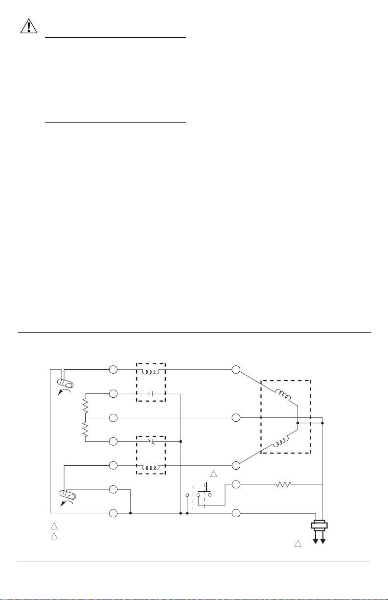
Fig. 2—Functional equivalent anticipator circuit of T641.
SOLID STATE RELAY
HEAT
FALL
RISE
1
POWER SUPPLY. PROVIDE DISCONNECT MEANS AND OVERLOAD PROTECTION AS REQUIRED.
ONLY T641B HAS SYSTEM OVERRIDE SWITCH.
2
COOL
HEAT
ANTICIPATOR
COOL
ANTICIPATOR
N.O.
SOLID STATE RELAY
N.C.
ON
SYSTEM
OVERIDE
2
OFF
W
C
Y
2
X
R
DAMPER CONTROL
DRIVE
CLOSED
COIL
DRIVE
OPEN
COIL
SYSTEM OVERIDE RELAY
1
L1
(HOT)
L2
M6112
Page 3

Fig. 3—Thermostat components and leveling procedure
FRONT OF THERMOSTAT
(COVER REMOVED)
SPIRIT LEVEL
MOUNTING
HOLES (4)
HEATING
CONTACT
COOLING
CONTACT
SYSTEM OVERRIDE
80
70
60
50
ON
OFF
Fig. 4—Mounting T641 using the accessory wallplate.
HONEYWELL PART NO. 221618
ACCESSORY WALLPLATE
WALLPLATE
INTERNAL
SET POINT
LEVER
MOUNTING
HOLES (4)
BACK OF THERMOSTAT
WIRING
TERMINAL
(UP TO 5)
Y
X
R
C
W
M 965
M6111
THERMOSTAT BASE
EXTERNAL
SET POINT LEVER
MOUNTING
SCREWS (4)
WARM
80
70
60
COOL
50
THERMOSTAT COVER
3 62-0101
Page 4

Fig. 5—ML6161 used with T641 for Type
damper applications. Y terminal will energize
counterclockwise winding on call for cooling,
driving motor open.
T641A THERMOSTAT
CY
R
CCW
120
VAC
SYSTEM
TRANSFORMER
M2257A
Fig. 6—T641B showing terminals X and C
energizing external relay when momentary
system override switch is pressed to ON
position.
R
24 VAC
X
PHASE SHIFT CAP.
DRIVE
CCW
WINDING
COMMON
T641B THERMOSTAT
CY
B
W
DRIVE
CW
WINDING
COM
MOTOR ML6161
Settings
TEMPERATURE SETTING
Move the heating and cooling set point levers to the
desired comfort positions. See Fig. 3.
SWITCH SETTING
T641B—momentary system override switch that in the
ON position will energize a relay that can be used in
CW
W
building management systems or other application.
The momentary override switch will output a 24 Vac
signal as long as the switch in held in the ON position.
In the OFF position, no output signal will be present.
For use in building management systems, the system
that the T641B interfaces with must be capable of
detecting a contact closure and respond accordingly to
perform a desired action.
T641C—manual heat/cool changeover switch. With this
switch set in the cool position, wire to damper actuator
as shown in Fig. 5. Be sure to determine direction of
damper opening for correct wiring between the T641
and ML6161. See Fig. 7. The changeover switch can
be placed in the heat position to reverse action at
terminals Y and W.
Fig. 7—Determining direction of damper opening
for correct wiring of ML6162 to T641.
120
VAC
SYSTEM
TRANSFORMER
24
VAC
CCW
DRIVE
CCW
WINDING
COMMON
EXTERNAL
RELAY
PHASE SHIFT CAP.
CW
DRIVE
CW
WINDING
COM
MOTOR ML6161
M2268
IMPORTANT: An incorrectly leveled thermostat will
cause the temperature control to deviate from set
point. It is not a calibration problem.
6. Install two screws in top mounting holes and tighten.
7. Replace the thermostat cover.
WARNING
Because the cooling anticipator operates continuously in the floating band, the T641 incorporates a
factory offset that calibrates the thermostat. The
offset causes the T641 to appear to be switching
10.5° F lower when not powered compared to
actual operation. The cooling anticipator is needed
to provide proper thermostat cycling by matching
the current draw of the ML6161 Actuator. To
ensure proper thermostat calibration and operation,
the C terminal must be used.
TYPE A DAMPER
Cooling
Air Flow
CW TO OPEN, CCW TO CLOSE
TYPE B DAMPER
Cooling
Air Flow
CCW TO OPEN, CW TO CLOSE
M2067A
NOTE: The ML6161 is designed to open a damper by
driving the damper shaft in either the clockwise (cw)
or counterclockwise (ccw) direction. To wire the
T641 correctly to the ML6161, see Figs. 5 and 7.
4
Page 5

Checkout
With the T641 controlling the ML6161 or equivalent
actuator, lower the set point of the thermostat to call for
cooling. Observe the operation of the motor. If the damper is
closed, it should begin to open. If not, adjust the set point of
the T641 higher to determine if the wiring is correct. If no
movement is observed, check for the presence of 24 Vac
between terminals C and Y during a call for cooling. With the
proper wiring and 24 Vac present, the actuator should operate
correctly. If 24 Vac is not present between C and Y on a call
for cooling, replace the T641.
To check out the ML6161 when controlled by the T641,
determine the direction the damper shaft moves to open the
damper (cw or ccw). See Fig. 7. Place 24 Vac across the
appropriate common-cw or common-ccw
terminals to energize the actuator. The ML6161 should
begin to open the damper. If the motor does not run, try
switching the 24 Vac across opposite common-cw or ccw
terminals to determine if the damper will begin to close.
Replace the ML6161 if the motor does not run in either
direction.
5 62-0101
Page 6

Automation and Control Solutions
Honeywell International Inc. Honeywell Limited—Honeywell Limitée
1985 Douglas Drive North 35 Dynamic Drive
Golden Valley, MN 55422 Scarborough, Ontario
M1V 4Z9
6
6
 Loading...