

Page 1
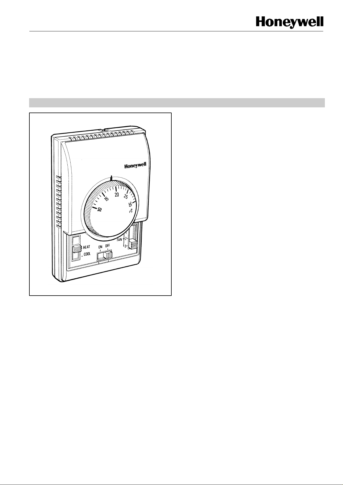
XE70 SERIES T6376/T6377
The T6376 and T6377 are designed
with the
FEATURES
•
Thermostat mounts directly onto a wall or conduit
THERMOSTATS
HEATPUMPS & SMALL AIR CONDITIONERS
PRODUCT SPECIFICATION SHEET
to control the valves,
the fan and the compressor in split units, heatpumps and
small air conditioners.
The thermostat operates the compressor to provide either
heating or cooling (as selected by the system switch) at
the desired setpoint temperature.
The fan can also be controlled from the thermostat. In some
cases it is wired to run continuously, and can be switched off
system ON/OFF switch, while with other models
there is a switch which gives the choice of running the fan
continuously, or cycling it with the thermostat.
Versions are available with a manual 3-SPEED FAN switch,
and with a system ON/OFF switch, or a HEAT/OFF/COOL
switch
Heat/cool changeover operation can be accomplished either
by a manually operated HEAT/FAN/ COOL switch or a
HEAT/OFF/ COOL switch on the front of the thermostat.
• Dual diaphragm sensing element ensures close
temperature control for all loads and applications
• Attractive modern styling makes this thermostat
ideal for locating in the occupied space, particularly
in offices or hotels
• Versions with heat anticipator, which improves
temperature control in both heating and cooling
operation
box
• Slide switches allow manual control of system
operation and fan speed
• Optional extras:
- rangestops F42006646-001
- tamperproof cover F42008489-001 (opaque),
F42008489-002 (transparent)
EN0R8405 R3 1998
Page 2
T6376/T6377 THERMOSTATS HEATPUMPS & SMALL AIR CONDITIONERS
SPECIFICATIONS
:
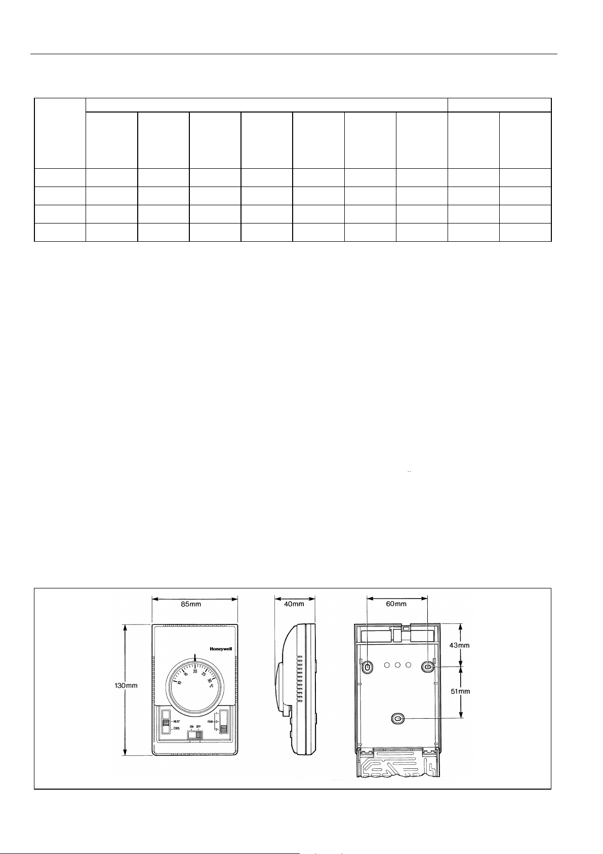
DIMENSIONS
Model Switches Features
ON/OFF 3-speed Fan/ Heat/Cool Heat/Cool Heat/Off/ Heat/Fan/ Fixed Auto
Fan Auto/Cont Cool Cool Deadband Change-
(SPST) (SPTT) (SPDT) (SPDT) (DPDT) (DPTT) (DPTT) (Aquastat)
T6376B1004
T6377B1003
T6377B1011
T6377B1045
4 4 4
4 4 4
4 4 4
4 4
over
Setpoint range: 10...30oC. By means of a large setpoint
dial
Supply voltage : 230 V~, 50...60 Hz
Thermostat
switch
Performance : Typical differential 1 oC (heating &
Electrical ratings : 4(2) A, 230 V~
Operational life : Greater than 100,000 cycles (all loads)
: S.P.D.T.
cooling) at 20oC at 50% load with
anticipator connected
Typical loads are fans, zone valves,
relays, compressors. Compressors of
greater than 0.5 kW capacity should be
switched via a contactor.
for thermostat contacts at 230 V~
Greater than 6,000 operations for all
manually operated switches
Mounting
Wiring : Up to 9 screw-in terminals per unit,
Enclosure : Plastic 2-piece housing
Dimensions : 85 x 130 x 40 mm (w x h x d)
Protection class : IP30
Environmental
requirements
Approvals : CE mark, complying with standards
Mounts directly onto wall or wall-box
(mounting screws supplied)
capable of accepting wires up to 1.5
2
mm
:
Operating temperature range 0 to 40oC
Shipping and storage temperature range
-20 to 50oC
Humidity range 0 to 90% rh, noncondensing
EN60730-1 (1995), EN55014-1 (1997),
EN55014-2 (1996).
Product must be wired as shown for CE
EN0R8405 R3 1998 2
Page 3

T6376/T6377 THERMOSTATS HEATPUMPS & SMALL AIR CONDITIONERS
INSTALLATION
OPERATION
wall or on a conduit box (see diagram). Mounting screws are
which disables all the outputs except that of the fan. In both
APPLICATION
T6376B
T6377B
T6377B
T6377B
Application
manual
manual
manual
Location
The XE70 Series thermostat is the temperature control
element in the fan-coil or air-conditioning system, and must
be located in a position with good air circulation, on an
inside wall about 1.5 m above the floor to sense the average
temperature. Do not position the thermostat in draughts,
near hot or cold air sources or where it will be affected by
radiant heat from the sun or other appliances.
Mounting the thermostat
Any XE70 Series thermostat can be directly mounted on the
supplied for both alternatives.
Wiring the thermostat
The standard wiring access is via a hole in the base of the
thermostat, near the top edge.
Sensing element
The thermostat sensing element comprises two circular,
flexible metal plates welded together at the rims and
encapsulating a gas/liquid combination whose pressure
changes in response to variations in temperature. This dualdiaphragm expands and contracts with ambient temperature
changes to operate a snap-acting switch which controls the
heating or cooling circuit.
Heat anticipator
It is recommended that the heat anticipator is always
connected for both heating and cooling operation.
1004 1003 1011 1045
Ventilation
2-pipe fan-coil
4-pipe fan-coil
Heatpump
Air-conditioner
[ [ [
[ [
IMPORTANT
1. The installer must be a trained service engineer
2. Disconnect the power supply before beginning
installation
Switches
All switches are slide switches for ease of operation.
The ON/OFF switch is a system on/off switch, as it removes
power from the thermostat.
The FAN SPEED switch allows selection of 3 different fan
speeds, 1 (low), 2 (medium), and 3 (high).
The FAN AUTO/CONT switch allows The choice of 2
different operating modes for the fan - either continuously
(cont), or cycled by the thermostat (auto)
The DPTT HEAT/OFF/COOL and HEAT/FAN/COOL
switches allow selection of either heating or cooling
operation, but also have an additional selection position
these cases the fan can be controlled separately, either by
the system ON/OFF switch or by the FAN AUTO/CONT
Heat or Cool
Heat/cool [ [ [ [
Control Changeover (auto or manual)
Capability Fan control (auto or cont) either cont either either
Fan speed control
Valve control
Compressor control
manual
[ [ [
[ [ [ [
[ [ [ [
EN0R8405 R3 19983
Page 4

T6376/T6377 THERMOSTATS HEATPUMPS & SMALL AIR CONDITIONERS
REVERSING
C/O
REVERSING
REVERSING
WIRING
ANTICIPATOR
HEAT C/O
COOLING
HEATING
HEAT C/O
COOL C/O
HEAT/
COOL
COOL
HEAT
/COOL
VALVE
VALVE
COMPRESSOR
LOAD
LOAD
FAN
REVERSING
VALVE
REVERSING
VALVE
COMPRESSOR
FAN
HEAT-PUMP
ANTICIPATOR
HEAT C/O
HEAT/COOL
ANTICIPATOR
HEATING
COOLING
HEAT/
COOL
VALVE
COMPRESSOR
FAN
HEAT-PUMP
LOAD
COMPRESSOR
FAN
AIR CONDITIONER
Honeywell Control Systems Limited http://europe.hbc.honeywell.com
Newhouse Industrial Estate
Motherwell ML1 5SB
United Kingdom
EN0R8405 R3 1998
 Loading...