

Page 1
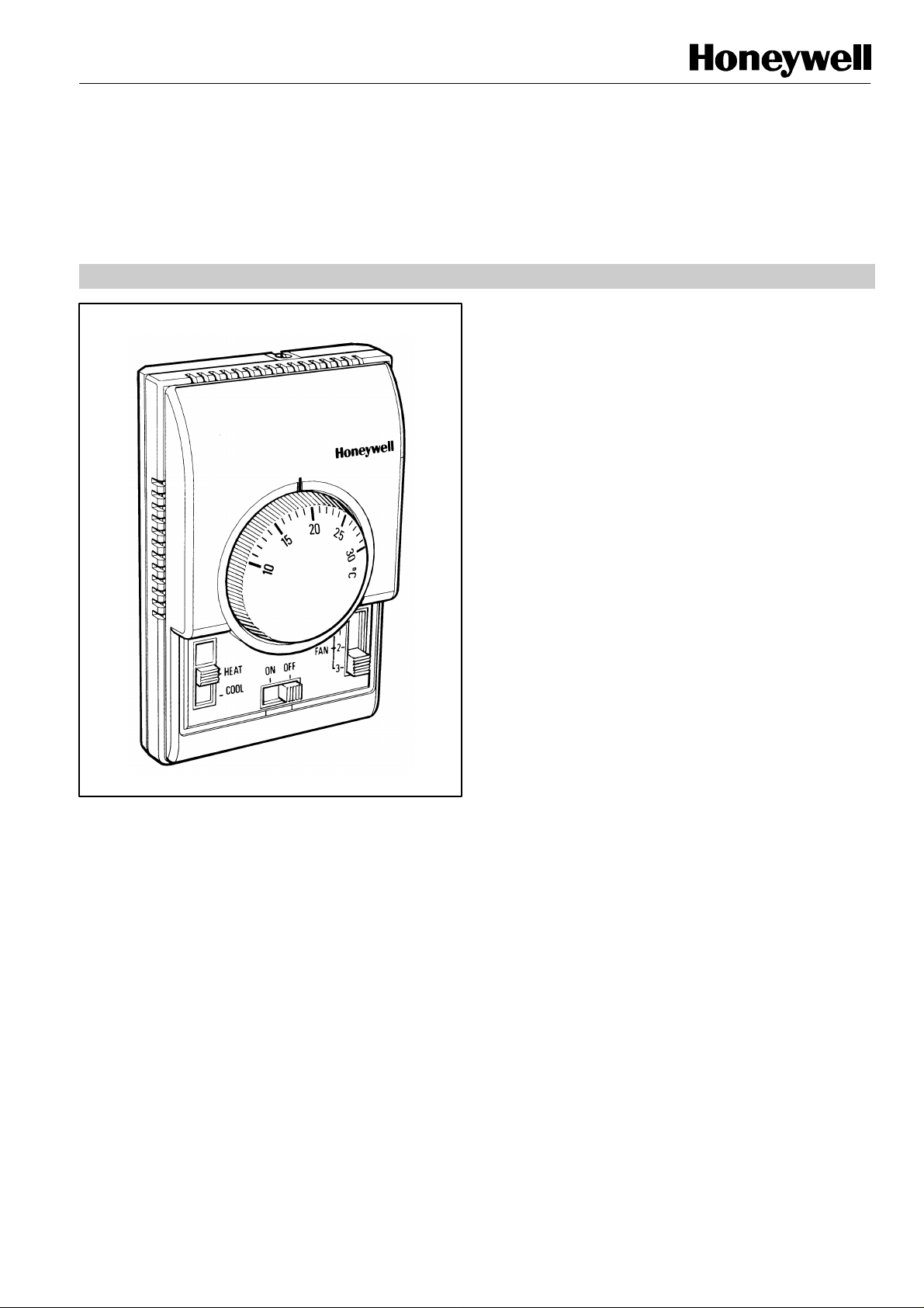
XE70 SERIES T6372/T6373
FEATURES
• • Slide switches allow manual control of system
FAN-COIL THERMOSTATS
2-PIPE FAN-COIL CONTROL
PRODUCT DATA
The T6372 and T6373 are designed to control the valve, or
the valve and the fan in 2-pipe fan-coil applications.
The thermostat operates an on/off valve to provide control at
the desired setpoint temperature.
The fan can also be controlled from the thermostat. In some
cases it is wired to run continuously, and can be switched off
with the system ON/OFF switch, while with other models
there is a choice of running the fan continuously, or cycling it
with the thermostat.
Versions are available with a manual 3-speed fan switch, and
with a system on-off switch.
Heat/cool changeover operation is also possible on some
versions. This function can be accomplished either by a
manually operated heat/ cool switch on the front of the
thermostat or in some versions automatically by the use of a
pipe thermostat on the supply water pipe of the fan-coil.
• • Dual diaphragm sensing element ensures close
temperature control for all loads and applications
• • Attractive modern styling makes this thermostat ideal
for locating in the occupied space, particularly in
offices or hotels
• • All versions have heat anticipator, which improves
temperature control in both heating and cooling
operation
• • Thermostat mounts directly onto a wall or conduit
box
operation and fan speed
• • Auto heat/cool changeover possible (on some
versions) by using pipe thermostat
• • Optional extras:
- range stops
- tamperproof cover
EN002-0903
Page 2
T6372/T6373 FAN -COIL TERMOSTATS 2-PIPE FAN-COIL CONTROL
SPECIFICATIONS
:
:
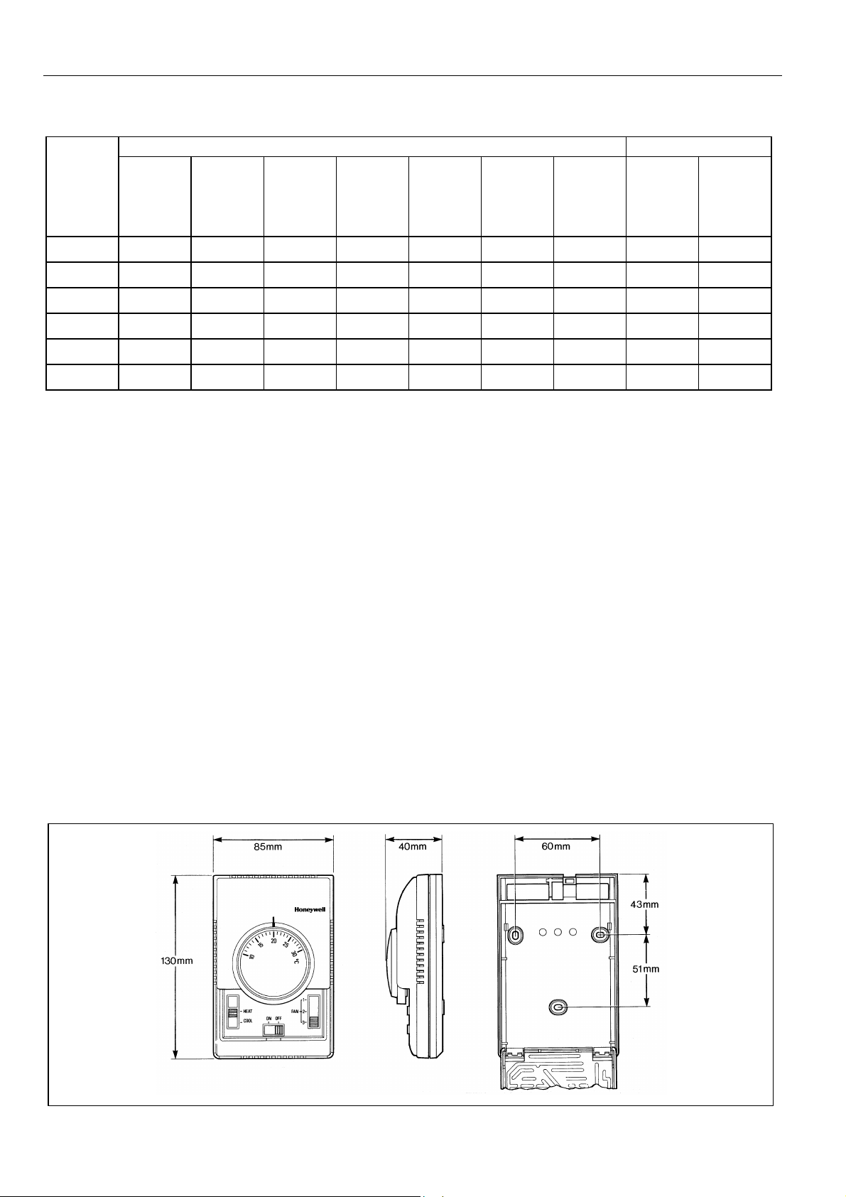
DIMENSIONS
Model Switches Features
ON/OFF 3-speed Fan/ Heat/Cool Heat/Cool Heat/Off/ Heat/Fan/ Fixed Auto
Fan Auto/Cont Cool Cool Deadband Change-
(SPST) (SPTT) (SPDT) (SPDT) (DPDT) (DPTT) (DPTT) (Aquastat)
T6372A1018
T6372B1024
T6372B1032
T6372C1014
T6373AC1108
T6373BC1130
4
4
4 4
4 4
4 4
4 4 4
over
Setpoint range
Supply voltage : 230 V~, 50...60 Hz
Thermostat
switch
Performance : Typical differential 1K (heating & cooling)
Electrical ratings : 4(2) A, 230 V~
Operational life : Greater than 100,000 cycles (all loads)
Mounting : Mounts directly onto wall or wall-box
10...30oC. By means of a large setpoint
dial
: S.P.D.T.
at 20oC at 50% load with anticipator
connected
Typical loads are fans, zone valves and
relays
for thermostat contacts at 230 V~
Greater than 6,000 operations for all
manually operated switches
(mounting screws supplied)
Wiring
Enclosure : Plastic 2-piece housing
Dimensions : 85 x 130 x 40 mm (w x h x d).
Protection class : IP30
RFI suppression Provided to B.S. EN 55014
Environmental
requirements
Approvals : Designed to meet harmoniosed EC
Up to 8 screw-in terminals per unit,
capable of accepting wires up to 1.5 mm
:
Operating temperature range 0 to 40oC
Shipping and storage temperature range
-20 to 50oC
Humidity range 0 to 90% rh, noncondensing
approvals standard IEC 730
2
EN002-0903 2
Page 3

T6372/T6373 FAN -COIL TERMOSTATS 2-PIPE FAN-COIL CONTROL
INSTALLATION
Location
The XE70 Series thermostat is the temperature control
element in the fan-coil or air-conditioning system, and must
be located in a position with good air circulation, on an inside
wall about 1.5 m above the floor to sense the average
temperature. Do not position the thermostat in draughts,
near hot or cold air sources or where it will be affected by
radiant heat from the sun or other appliances.
Mounting the thermostat
Any XE70 Series thermostat can be directly mounted on the
wall or on a conduit box (see diagram). Mounting screws are
supplied for both alternatives.
Wiring the thermostat
The standard wiring access is via a hole in the base of the
thermostat, near the top edge.
OPERATION
Sensing element
The thermostat sensing element comprises two circular,
flexible metal plates welded together at the rims and
encapsulating a gas/liquid combination whose pressure
changes in response to variations in temperature. This dualdiaphragm expands and contracts with ambient temperature
changes to operate a snap-acting switch which controls the
heating or cooling circuit.
Heat anticipator
It is recommended that the heat anticipator is always
connected for both heating and cooling operation.
Application
T6372A T6372B T6372B T6372C T6373AC T6373BC
1018 1024 1032 1014 1108 1130
Ventilation F F F
2-pipe fan-coil
Application 4-pipe fan-coil
Heatpump
Air-conditioner
F F F F F F
IMPORTANT
1. The installer must be a trained service engineer
2. Disconnect the power supply before beginning
installation
Switches
All switches are slide switches for ease of operation.
The ON/OFF switch is a system on/off switch, as it removes
power from the thermostat.
The FAN SPEED switch allows selection of 3 different fan
speeds, 1 (low), 2 (medium), and 3 (high)
The SPDT HEAT/COOL switch allows selection of either
heating or cooling operation. There is only a single output
connection capable of powering a fan or a single zone valve
in a 2-pipe fan-coil unit.
Control Changeover (auto or manual) manual manual auto manual
Capability Fan control (auto or cont) a or c a or c a or c a or c cont cont
Heat or Cool F F
Heat/cool
Fan speed control
Valve control
Compressor control
F F F F F F
F F F F
F F
EN002-09033
Page 4

T6372/T6373 FAN -COIL TERMOSTATS 2-PIPE FAN-COIL CONTROL
WIRING
T6373AC1108
T6373BC1130
ANTICIPATOR
HEAT
COOL
CLOSE VALVE
ANTICIPATOR
HEAT/COOL
CLOSE
VALVE
CLOSE VALVE
VALVE
VALVE
VALVE
FAN
FAN
ANTICIPATOR
HEAT/COOL
CLOSE
VALVE
ANTICIPATOR
HEAT
COOL
VALVE
FAN
VALVE
FAN
ANTICIPATOR
HEAT
COOL
CLOSE VALVE
ANTICIPATOR
HEAT/COOL
link 4 & 5 for fan continuous, 3 & 5 for fan automatic (cycled)
VALVE
VALVE
LOAD
FAN
FAN
ANTICIPATOR
HEAT/COOL
CLOSE
VALVE
CLOSE VALVE
ANTICIPATOR
HEAT
COOL
VALVE
FAN
VALVE
FAN
Honeywell Limited
25/F Honeywell Tower
Olympia Plaza
255 King's Road
North Point, Hong Kong
EN002-0903
 Loading...