

Page 1
AU4360I-01 1
T4360G, T6360D, T6360E
Line Voltage Thermostat
APPLICATION
The T4360G thermostat with on/off switch provides control of 240Vac heat only (16A) or cool only (10A)
systems with the optional indicator light operating on temperature fall. The T6360D thermostat with on/off
switch provides control of 240Vac cool only or heat only systems with the optional indicator light operating
on temperature rise. The T6360E thermostats provide control of 240Vac heat pump systems with or without
fan control.
INSTALLATION
When Installing this Product…
1. Read these instructions carefully. Failure to follow the
instructions can damage the product or cause a
hazardous condition.
2. Check the ratings given in the instructions and on the
product to make sure the product is suitable for your
application.
3. Installer must be a trained, registered electrician or
service technician.
4. After completing installation, use these instructions to
check out the product operation.
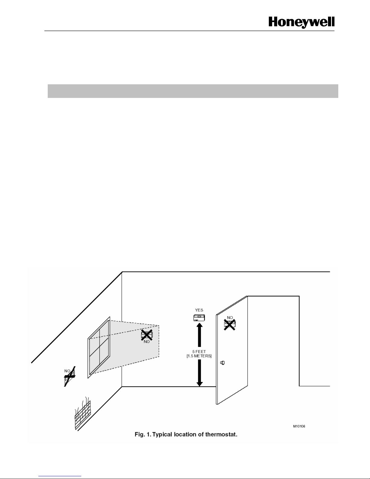
Location
Install the thermostat about 5 ft (1.5m) above the floor in an
area with good air circulation at average temperature. See
Fig. 1.
Do not install the thermostat where it can be affected by:
— Drafts, or dead spots behind doors and in corners.
— Hot or cold air from ducts.
— Radiant heat from sun or appliances.
— concealed pipes and chimneys.
— unheated (uncooled) areas such as an outside wall
behind the thermostat.
INSTALLATION INSTRUCTIONS
Page 2
T4360G, T6360D,E Line Voltage Thermostat
AU4360I-01 2
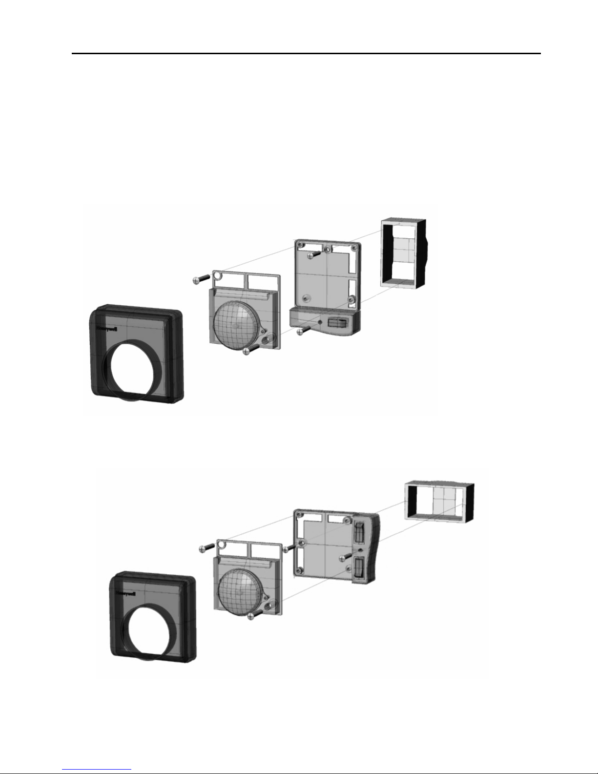
Sub Base Installation
The thermostat can be mounted horizontally or vertically
on the wall or a wall plate/box. Refer to Figs 2 and 3.
1. Position and level the sub base (for appearance
only). The thermostat will function properly even
when not level.
2. Use a pencil to mark the mounting holes.
3. Remove the sub base from the wall and drill two
holes in the wall as marked. Gently tap anchors into
the drilled holes until flush with the wall.
4. Position the sub base over the holes, pulling wires
through the wiring opening.
5. Loosely insert the mounting screws into the holes.
6. Tighten mounting screws.
Fig 2: Vertical Installation diagram
Fig 3: Horizontal Installation diagram
Page 3

T4360G, T6360D,E Line Voltage Thermostat
AU4360I-01
3
Wiring
All wiring must comply with local electrical codes and
ordinances. Refer to Figs. 4 - 8 for typical wiring. A
number code is located near each terminal for
identification.
1. Loosen the terminal screws on the subbase and
connect the fan wires (T6360E fan models only).
2. Remove the cover from the thermostat and attach
thermostat base to subbase.
3. Loosen the terminal screws on the thermostat
base and connect the system wires (all models).
4. Replace thermostat cover.
CAUTION
Disconnect power before wiring to prevent
electrical shock or equipment damage.
WIRING DIAGRAMS
b)a)
OPTIONAL - LAMP CONNECTION
b) Terminal #4 for cooling
a) Terminal #3 for heating
TERMINAL OPTION:
SUBBASE LEADS
T4360G1006
LINE
(240Vac)
1
2
23415
Fig 4: T4360G1006 (Heat or Cool, light operates on temp fall) wiring diagram
51432
2
1
(240Vac)
LINE
SUBBASE LEADS
TERMINAL OPTION:
a) Terminal #3 for heating
b) Terminal #4 for cooling
a) b)
OPTIONAL - LAMP CONNECTION
T6360D1008
Fig 5: T6360D1008 (Cool or Heat, light operates on temp rise) wiring diagram
Page 4

AU4360I-01 4
Fig 6: T6360E1005 (Heat Pump Heat/Off/Cool) wiring diagram
Fig 7: T6360E1013 (Heat Pump Heat/Off/Cool Cont/Auto Fan) wiring diagram
Fig 8: T6360E1021 (Heat Pump Heat/Off/Cool Lo/Med/Hi Fan) wiring diagram
Environmental Controls
Honeywell
2 Richardson Place
North Ryde NSW 2113
T6360E1005
L
N
(240Vac)
LINE
REVERSING
VALVE
51432 6
COMPRESSOR
OPTIONAL - LAMP CONNECTION
SUBBASE LEADS
42
3
COMP.
623415
REVERSING
VALVE
LINE
(240Vac)
N
L
T6360E1013
9
FAN
SUBBASE LEADS
42
3
OPTIONAL - LAMP CONNECTION
1
7
T6360E1021
51432 6
8
9
Hi
Lo
Med
COMP.
L
(240Vac)
LINE
N
REVERSING
VALVE
FAN
OPTIONAL - LAMP CONNECTION
SUBBASE LEADS
423
1
 Loading...