

Page 1
T6120A,B
SINGLE- AND DUAL-STAGE
INDUSTRIAL ROOM THERMOSTATS
SPECIFICATION DATA AND MOUNTING INSTRUCTIONS
GENERAL
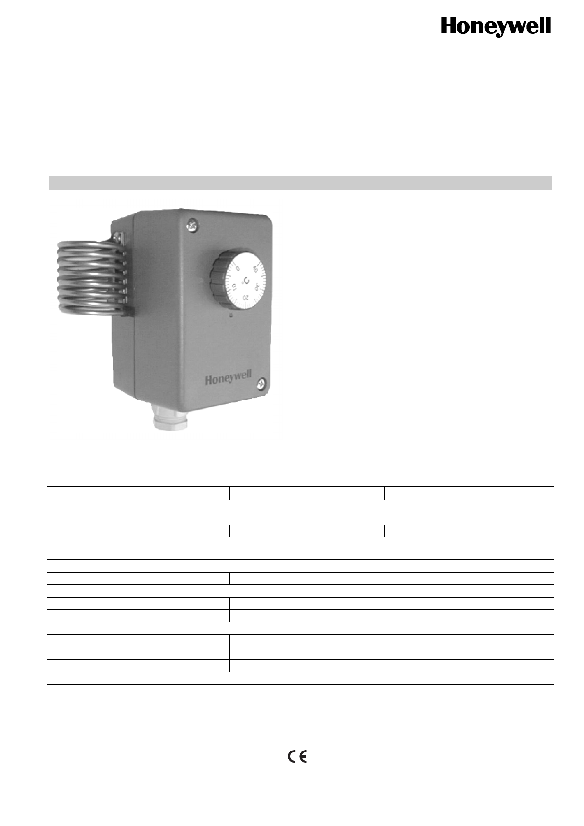
The T6120A and B Single- and Dual-Stage Industrial Room
Thermostats are designed for measuring, monitoring, and
controlling temperatures in heating and cooling systems.
These thermostats are suitable for the following areas of
applications:
· commercial buildings,
· storage rooms,
· garages,
· machine rooms,
· factories,
· greenhouses, and
· agricultural installations.
FEATURES
· Liquid-filled stainless steel or copper (T6120A1005, only)
bulb.
· Rugged design.
· Easy installation and wiring connection.
· Dust-tight microswitches with switching contacts for
heating and cooling.
MODELS
T6120A1005 T6120A1013 T6120A1021 T6120A1039 T6120B1003
no. of stages 1 2
switch contact 1 SPDT 2 SPDT
hysteresis 1 K (fixed) 2...15 K (adjustable) 1 K (fixed) 1 K (fixed)
switching differential
between stages
adjustment range 0...60 °C -30...+30 °C
working temperature -10...+65 °C -35...+65 °C
storage temperature -20...+70 °C
current 10 (1.5) A 15 (8) A
voltage 250 Vac 24...250 Vac
housing ABS, re-inforced
sensor material 1.4301 copper
weight 360 g 530 g
protection standard IP54 IP65
W x H x L (mm) 108 x 70 x 72
Copyright © 2004 Honeywell Inc.
All Rights Reserved EN0B-0317GE51 0304
n.a. 2...10 K (adjustable)
Page 2
T6120A,B SINGLE- AND DUAL-STAGE INDUSTRIAL ROOM THERMOSTATS
T6120A1005
Function and Wiring
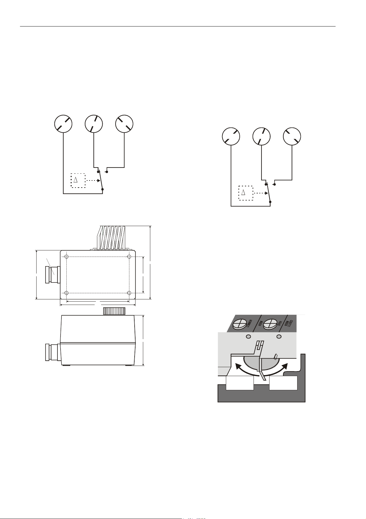
To control a heating unit, connect terminals 2 and 3 of the
thermostat to the heating unit. When the temperature rises,
the contact will open (see Fig. 1).
To control a cooling unit, connect terminals 1 and 2 of the
thermostat to the cooling unit. When the temperature
drops, the contact will open (see Fig. 1).
2 3 1
T
Fig. 1. T6120A1005 wiring
Dimensions
T6120A1013/A1021/A1039
Function and Wiring
To control a heating unit, connect the red terminal
("COMMON") and the blue terminal ("NORM OPEN") of the
thermostat to the heating unit. When the temperature rises,
the contact will open (see Fig. 3).
To control a cooling unit, connect the red terminal
("COMMON") and white terminal ("NORM CLOSED") of the
thermostat to the cooling unit. When the temperature
drops, the contact will open (see Fig. 3).
whitebluered
T
Fig. 3. Wiring T6120A1013/1021/1039 and T6120B1003
PG 13.5
90
108
Fig. 2. Dimensions T6120A1005 (in mm)
Adjusting the Hysteresis
(T6120A1013/A1021, only)
In the case of the T6120A1013/A1021 Single-Stage
105
5270
72
Thermostats, it is possible to adjust the hysteresis to a
value of between 2 K (factory setting) and 15 K. This can
be done as follows:
Pull off the adjustment knob, unscrew the two fastening
screws, and remove the housing cover. The hysteresis
adjustment dial is now visible (see Fig. 4). The dial settings
are numbered from "2" (corresponding to the min. setting
of 2 K) to "15" (corresponding to the max. setting of 15 K).
dial
increasing
hysteresis
(max.: 15 K)
Fig. 4. Adjusting the hysteresis (T6120A1013/A1021,
only)
decreasing
hysteresis
(min.: 2 K)
EN0B-0317GE51 R0304 2
Page 3

T6120A,B SINGLE- AND DUAL-STAGE INDUSTRIAL ROOM THERMOSTATS
Dimensions
PG 11
26 5270
90
108
150
86
72
20
Fig. 5. Dimensions T6120A1013/A1021/A1039 and
T6120B1003 (in mm)
T6120B1003
Function and Wiring
To control a heating unit, connect the red terminal and the
blue terminal of both stages of the thermostat to the
corresponding terminals of the heating unit (see Fig. 6).
When the temperature rises, the contact of stage 1 will
open; if the temperature rises an additional value
corresponding to the set switching differential (see section
"Adjusting the Switching Differential between Stages"), the
contact of stage 2 will then likewise open.
To control a cooling unit, connect the red terminal and
white terminal of both stages of the thermostat to the
corresponding terminals of the cooling unit (see Fig. 6).
When the temperature drops, the contact of stage 1 will
open; if the temperature drops an additional value
corresponding to the set switching differential (see section
"Adjusting the Switching Differential between Stages"), the
contact of stage 2 will then likewise open.
stage 1 stage 2
whitebluered whitebluered
T
Fig. 6. Wiring T6120B1003
Adjusting the Switching Differential
between Stages
In the case of the T6120B1003 Dual-Stage Thermostat, it
is possible to adjust the switching differential (i.e. the
difference in temperatures at which the two stages are
activated) to a value of between 2 K (factory setting) and
10 K. This can be done as follows:
Pull off the adjustment knob, unscrew the two fastening
screws, and remove the housing cover. The switching
differential adjustment lever is now visible (see ). Sliding
the lever to the right increases (max.: 10 K) the switching
differential. Sliding it to the left decreases (min.: 2 K) the
switching differential.
lever
10 K
decreasing
hysteresis
(min.: 2 K)
2 K
increasing
hysteresis
(max.: 10 K)
Fig. 7. Adjusting the switching differential
EN0B-0317GE51 R03043
Page 4

T6120A,B SINGLE- AND DUAL-STAGE INDUSTRIAL ROOM THERMOSTATS
Automation and Control Solutions
Honeywell GmbH
P.O. Box 1254
D-71099 Schönaich
Phone: (49) 7031-637-02
Fax: (49) 7031-637-850
http:/honeywell.de/fema
Subject to change without notice. Printed in Germany Manufacturing location certified to
EN0B-0317GE51 R0304
 Loading...