

Page 1

APPLICATION
The T4051, T6051, and T6052 are heavy duty. line
voltage thermostats used to control fan coils, fans, motor T6051A gleat)b 1 Full load
starters, valves, contactors, and circulator motors in
heating and/or cooling systems.
The T4051 A is for heating only control. The T4051 B and cool)
‘IS for cooling only control. The T4051D is for electric
‘heat applications and is used without a subbase.
TABLE I-ELECTRICAL RATINGS (AMPS)
T4051A.B.Da I I
76052AI.Lagel)~I~ ,I /
T6052B (Auto i ;ii.i
changeover heat Locked rotm 96
T605tA (cool)
T6052A (stage 2) Locked rotor 48 ~24
Full&ad :~ 8 4
i12OV AC1240V AC
I
1 16 1, 8
/ 4B
The T6051A may be used in heating only systems,
cooling only ‘systems, combination heat-cool systems
,(changeover must be provided), or as a series 60 controller for valves and motors.
: The T6052A is for two stage heating or two stage
jcooling systems. The T6052B is for one stage heating-
cooling systems with automatic changeover.
The 0651 Subbase may be used with the thermostats
bo provide system switching at the thermostat location.
iRefer to applicable specification sheet for additional
mformation.
~Electrical ratings for the heavy duty thermostats are
given in Table 1.
aT4051D also has non-inductive rating: 19 amps at
277~ ac; 22 amps at 12Ol24Ov ac.
bT6051 D may be used without subbase for 22 amp non-
inductive load switching.
Pilot duty rating (all models): 125 va.
INSTALLATION
CAUTION
1. Disconnect power supply before making wiring
connections to prevent electrical shock and
!
equipment damage.
2. Installer must be a trained, experienced
serviceman.
3. Always conduct a thorough checkout when installation is complete.
Rev. 6-72
ES.
Fig. l-Mounting therlmostat to outlet box.
Form NlirnbF,
95-6979-l
R es, S" 10 D,.. '2 ,' /
Page 2
LOCATION
Locate the thermostat about five feet above the floor
on an inside wall where it will be affected only by the
average temperature of the room. These thermostats are
:mounted vertically.
If using a Q651 Subbase, refer to the instructions
packed with the subbase.
MOUNTING
1. Mount a 2,by 4 inch outlet box either vertically
or horizontally depending on the model used. Models
with vertical faceplate mount on vertical outlet box;
models with horizontal faceplate mount on horizontal
outlet box.
2. Run conduit between the outlet box, powersource,
and the unit being controlled. Leave about six inches
of wire in the box forconnections. (Refertothe WIRING
section for the number of wires required.)
3. Place the mounting plate on the outlet box. Insert
the two furnished mounting screws, leaving theme loose
enough to move the mounting plate for leveling.
4. Level the mounting plate and tighten the mounting
screws. (See Fig. 1.)
5. Connect the heating and/or cooling system wires
or the series 60 equipment wires to the back terminals
of the thermostat. (See Figs. 2 through 12.)
6. When wiring is complete, secure the fiber insulator on all models except the T4051 B by snapping the
holes in the flap over the switch rivet heads. When
the normally open switch terminal is used, clip the
flap to allow it to pass around the wire. On the T4051 B,
secure the flap by snapping it over a projection on the,
molded resistor cover.
7. Hang thermostat on mounting plate tabs. (See
Fig. 1.)
8. Take socket-head cover mounting screw (fur- The T4051D~ is used to control electric heating
nished) and insert it into tab at bottom of base. Do not equipment. It makes on temperature fall and breaks on
tighten. Replace cover. temperature rise. Because it has a higher load rating,
9. Insert set point knob into socket-head screw the T4051 D should NOT be used with a subbase.
and tighten. This fastens cover and thermostat to the
mounting plate previously attached to outlet box. Remove knob.
The T40516 is for cooling equipment control. The
switch makes on a rise in temperature and breaks on a
fall in temperature. Subbase is available.
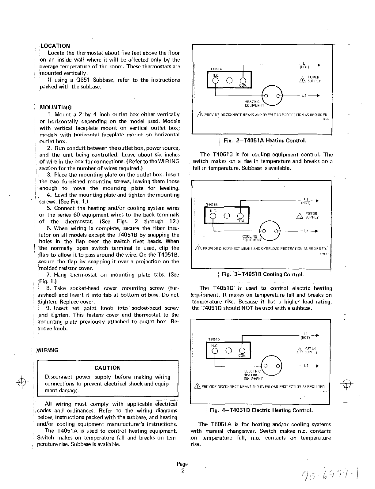
Fig. Z-T4051A Heating Control.
Fig. 3-T4051 B Cooling Control.
WIRING
CAUTION
Disconnect power supply before making wiring
connections to prevent electrical shock and equipment damage.
All wiring must comply with applicable electrical
codes and ordinances. Refer to the wiring diagrams
below, instructions packed with the subbase, and heating
and/or cooling equipment manufacturer’s instructioiw.
The T4051A is used to control heating equipment. with manual changeover. Switch makes n.c. contacts
Switch makes on temperature fall and breaks on tem- on temperature fall, n.0. Contacts on temperature
perature rise. Subbase is available. rise.
Fig. 4-T4051 D Electric Heating Control.
The T6051A is for heating and/or cooling systems
Page 3

i Fig. 5-T6051A in heating only application.
: ‘Fig. 6-T6051A ‘in,,cooling only application.
I. 9-T6051A used as a series 60 controller, 3.wire,
line voltage, two position control.
The T6052A is for two stage heating or cooling
systems. Switches make stages 1 and 2 in sequence.
The T605’2B is for heating-cooling with auto changeover;
stage 1 makes on temperature fall; stage 2 makes on
temperature rise.
ig. 7-T6051A in heat-cool control for separate heating,
and cooling equipment.
g. 8-T6051A Heat-Cool Control for combination
heating-cooling equipment.
Fig. IO-Typical hookup of T6052A to control tn
stage heating system.
Page
3
95-6979-l
Page 4

Fig
I. 12-Typical hookup of T6052B to control heating-
cooling system with auto changeover.
ELEVATION
(IN FEET)
0 to 2,000
2,000 to 4,000 Move counterclockwise 1 notch
to
4,000
6,000 and above Move counterclockwise 3 notches
TO LOCK
After altitude adjustment is complete, replace the
cover and cover setscrew. Move the set point indicator
to the desired temperature setting. Remove the set point
knob to lock the set point.
6,000 Move counterclockwise 2 notches
INDICATOR
Leave as is
,‘AL TITUDE CALIBRATION
This thermostat was calibrated at the factory for
accuracy at 1,000 feet above sea level. It may be
necessary to reset the thermostat for the altitude of
your locality. If you do not know your altitude,eonsult
your local U.S. Weather Bureau or Public Library.
I
I I
~ Fig. 13-Altitude calibr&ion.
Each notch on the calibration mechanism represents
2,000 feet. If you are above sea level use the chart to
determine how far to move the indicator.
OPERATION AND CHECKOUT
After the thermostat is installed and wired, operate
it manually to make certain it is connected properly.
Checkout will depend on type of hookup and controlled
equipment.
,
F~or cooling control check, turn the setting knob to
move the indicator down the scale. This initiates a
call for cooling, and the cooling equipment should
respond. For heating control check, turn the setting
knob to move the indicator up the scale. This initiates
‘a calls for heat, and the heating equipment should
:heating and cooling as described above. For series 60
control check, cycle the equipment through the T6051A
and make sure it functions as intended.
internal pressure. Rapid cycling might damage
compressor and overload electrical circuit.
By using this Honeywell literature, you agree that Honeywell will have no liability for any damages arising out of your use or modification to, the
literature. You will defend and indemnify Honeywell, its affiliates and subsidiaries, from and against any liability, cost, or damages, including
attorneys’ fees, arising out of, or resulting from, any modification to the literature by you.
 Loading...