

Page 1
HONEYWELL I
TRADELINE
I CONTROLS
T6051 A; T6052A.B
HEAVY DUTY THERMOSTATS
The T6051 Heavy Duty Thermostat may be used in
heating only systems, cooling only systems, combination
heat-cool systems (system changeover means must be
provided), or as a series 60 controller for valves or motors.
The T6052A is for two stage heating or two stage
cooling systems. The T6052B is for one stage heatingcooling systems with automatic changeover.
The Q651 Subbase may be used with the T6051 and
T6052B thermostats to provide system witching at the
thermostat location. Refer to applicable specification
sheet for additional information.
INSTALLATION
---
--------------------------------------—
LOCATION
Locate the thermostat about five feet above the floor
on an inside wall where it will be affected only by the
average temperature of the room. The T6051A may be
mounted either vertically or horizontally.
If using a 0651 Subbase, refer to the instructions
packed with the subbase.
MOUNTING
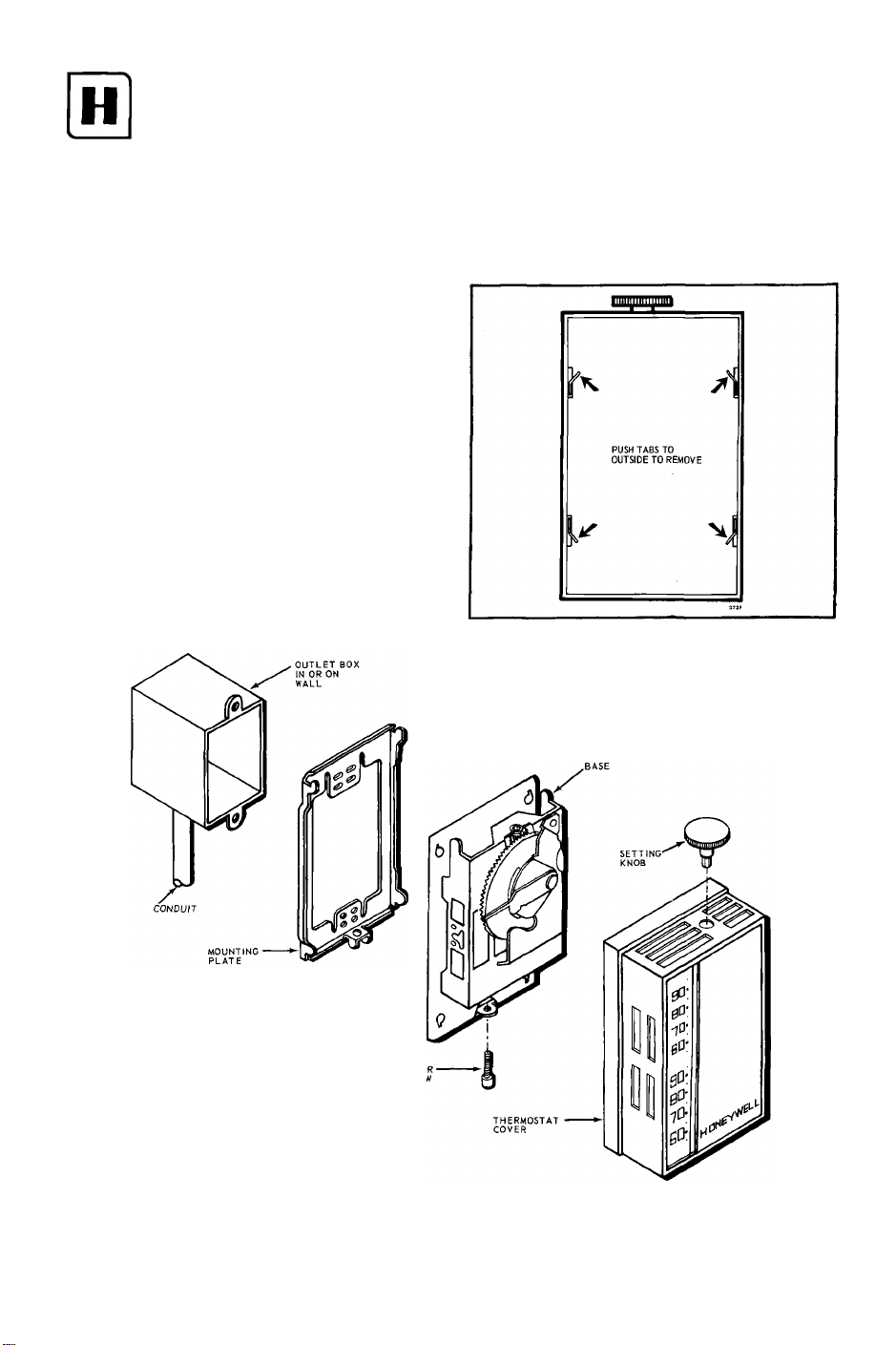
1. If mounting horizontally, coverplate must be
changed. To remove vertical coverplate, bend four
corner tabs to outside and oush out on cover. Place
horizontal coverplate on cover frame and bend four
corner tabs to inside. (See Fig. 1).
Fig. 1—Changing coverplate for horizontal mounting.
2-72
E.S.
Fig. 2—Mounting Thermostat on Outlet Box.
THERMOSTAT
Form Number
95-6980-1
Residential Div.
Page 2
2. Mount the 2 by 4 inch outlet box either vertically
or horizontally, as desired.
3. Run conduit between the outlet box, power source,
and the unit being controlled. Leave about six inches of
wire in the box for connections. (Refer to the WIRING
section for the number of wires required.)
4. Place the mounting plate on the outlet box either
vertically or horizontally. Insert the two furnished
mounting screws, leaving them loose enough to move
the mounting plate for leveling. See Fig. 2.
5. Level the mounting plate and tighten the mounting
screws. (See Fig. 2.)
6. Connect the heating and/or cooling system wires
or the Series 60 equipment wires to the back terminals
of the thermostat. See Figs. 3—10.
7. When wiring is complete, secure the fiber insulator
by snapping the holes in the flap over the switch rivet
heads. When the normally open terminal is used, clip the
flap to allow it to pass around the wire.
8. Hang thermostat on mounting plate tabs, see
Fig. 2.
9. Take socket-head cover mounting screw (furnished)
and insert it in tab at bottom of base. Do not tighten.
Replace cover.
10. Insert set point knob into socket-head screw and
tighten. This fastens cover and thermostat to the mount
ing plate previously attached to outlet box. Remove knob.
WIRING
CAUTION
Disconnect power supply before making wiring
connections to prevent electrical shock and
equipment damage.
All wiring must agree with local electrical codes and
ordinances. Refer to the wiring diagrams below, instruc
tions packed with the subbase, and heating and/or cooling
equipment manufacturer's instructions.
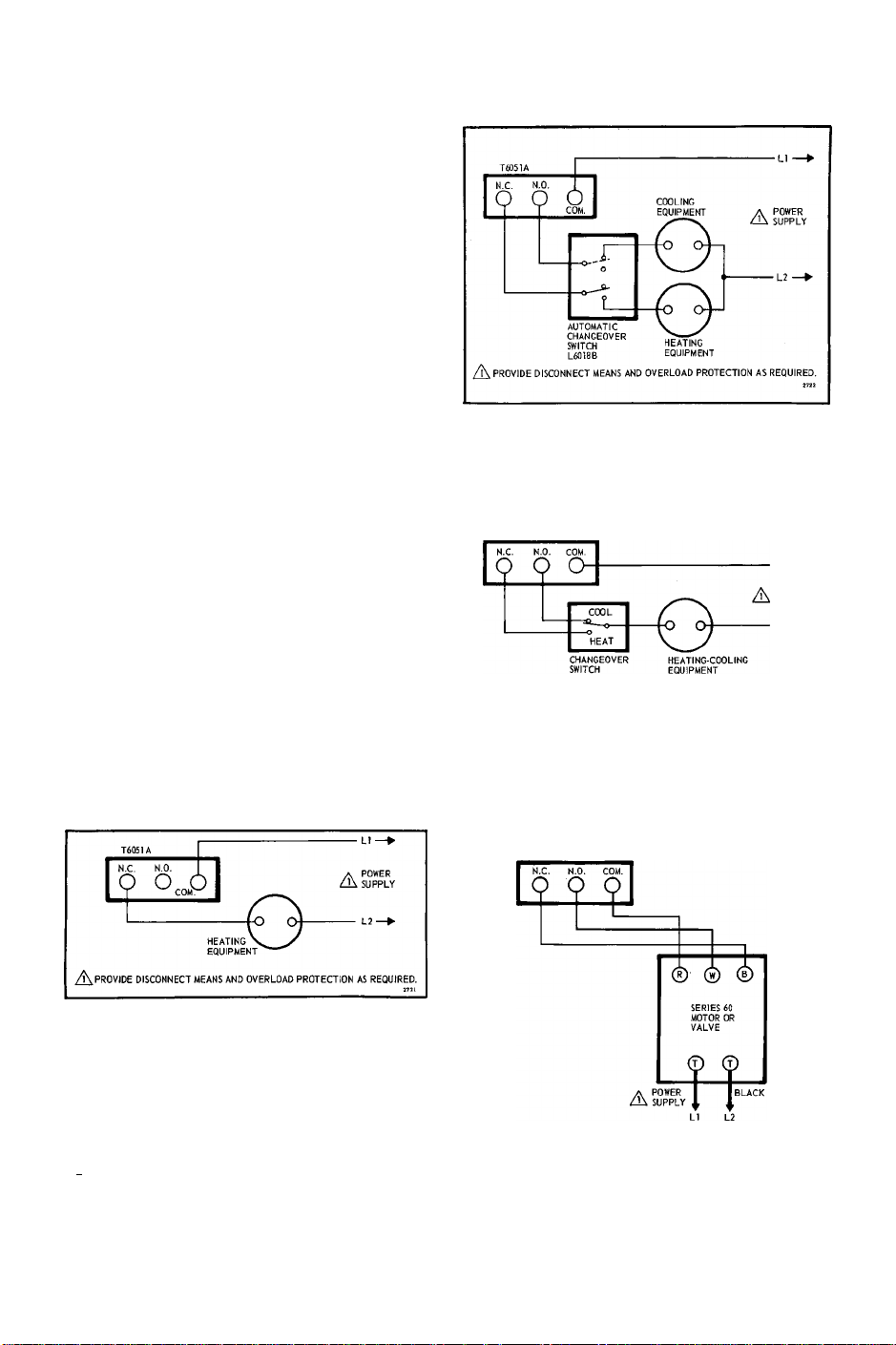
Fig. 5-T6051A heating-cooling control for separate
heating and cooling equipment.
/^PROVIDE DISCONNECT MEANS AND OVERLOAD PROTECTION AS REQUIRED.
Fig. 6—T6051 heating-cooling control with changeover
switch for combination heating-cooling
equipment.
POWER
SUPPLY
Fig. 3—T6051A used in heating only application.
N.C. N.O
O ‘
cooLmc
EQUIPMENT.O'
/i\ PROVIDE DISCONNECT MEANS AND OVERLOAD PROTECTION AS REQUIRED.
A
POWER
Fig. 4—T6051A used in cooling only application.
SUPPLY
PROVIDE DISCONNECT MEANS AND OVERLOAD PROTECTION AS REQUIRED.
A
Fig. 7—T6051 used as a series 60 control. 3-wire, line
voltage, two position control.
Page
2
Page 3

POWER
SUPPLY
A
/К PROVIDE DISCONNECT MEANS AND OVERLOAD
PROTECTION AS REQUIRED.
Fig. 8--Typical hookup of T6052A to control two
stage heating system.
A\ PROVIDE DISCONNECT MEANS AND OVERLOAD
PROTECTION AS REQUIRED.
Fig. 9—Typical hookup of T6052A to control two
stage cooling system.
POWER
SUPPLY
A
POWER
SUPPLY
Each notch on the calibration mechanism represents
2,000 feet. If you are above sea level use the chart to
determine how far to move the indicator:
ALTITUDE CALIBRATION
This thermostat was calibrated at the factory for
accuracy at 1,000 feet above sea level. It may be nec
essary to reset the thermostat for the altitude of your
locality. If you do not know your altitude, consult your
local U.S. Weather Bureau or Public Library.
Elevation (in feet)
0 to 2,000
2,000 to 4,000
4,000 to 6,000
6,000 and above
OPERATION AND CHECKOUT
Indicator
Leave as is
Move down 1 notch
Move down 2 notches
Move down 3 notches
------------------------
After the thermostat is installed and wired, operate
it manually to make certain it is connected properly.
Checkout will depend on type of hookup and controlled
equipment. For cooling control check, turn the setting
knob to move the indicator down the scale. This ini
tiates a call for cooling and the cooling equipment
should respond. For heating control check, turn the
setting knob to move the indicator up the scale. This
initiates a call for heat, and the heating equipment
should respond. For heating/cooling control, check
both heating and cooling as described above. For
Series 60 control check, cycle the equipment through
A
the T6051A and make sure it functions as intended.
CAUTION
If the thermostat is controlling a compressor, allow
at least two minutes between on cycles to equalize
the internal pressure. Rapid cycling might damage
the compressor and overload the electrical circuit.
Д PROVIDE DISCONNECT MEANS AND OVERLOAD
PROTECTION AS REQUIRED.
Fig. 10—Typical hookup of T6052B to control heating
cooling system with auto changeover.
TO LOCK
After altitude adjustment is complete, replace the
cover and set cover screw with set point knob. With
the knob again in place, move the set point indicator
to the desired temperature setting. Remove the set
point knob to lock the set point.
Page
3
Page 4

WARRANTY “Utüess otherwise specified, the Company warrants all Residential Division equipment manufactured by It and bearing its nameplate to be free from defects in worhmandiip
and materials under normal use and service as follows:
1. Equipment which is received transportation prepaid at the factory originating shipment (1) within twelve months after date of manufacture, or (2) with a certification by the installer to be
within twelve months after date of installation, and found by the Company’s inspection to be defective in workmanship or materials within the guarantee, will be repaired or replaced at the
Company's option, free of charge and returned lovrest cost transportation prepaid. Premium transportation will be used at customer's request and expense;
2. If inspection by the Company does not disclose any defect covered by the guarantee, equipment will be repaired or replaced and the Company's regular service charge will apply;
3. WITH EXCEPTION OF THE FOREGOING AND UNLESS SPECIFICALLY EXPRESSED IN WRITING, THE COMPANY MAKES NO EXPRESS WARRANTIES, NO WARRAN’HES
OF MERCHANTABILITY AND NO WARRANTIES WHICH EXTEND BEYOND THE DESCRIPTION OF THE FACE HEREOF."___________________________________________
HONEYWELL MINNEAPOLIS, MINN. 55408 INTERNATIONAL Sales Offices in all principal cities of the world. Manufacturing in Australia, Canada, Finland, France, Germany, Japan,
Mexico, Netherlands, Spain, Taiwan, United Kingdom, U.S.A.
 Loading...