

Page 1
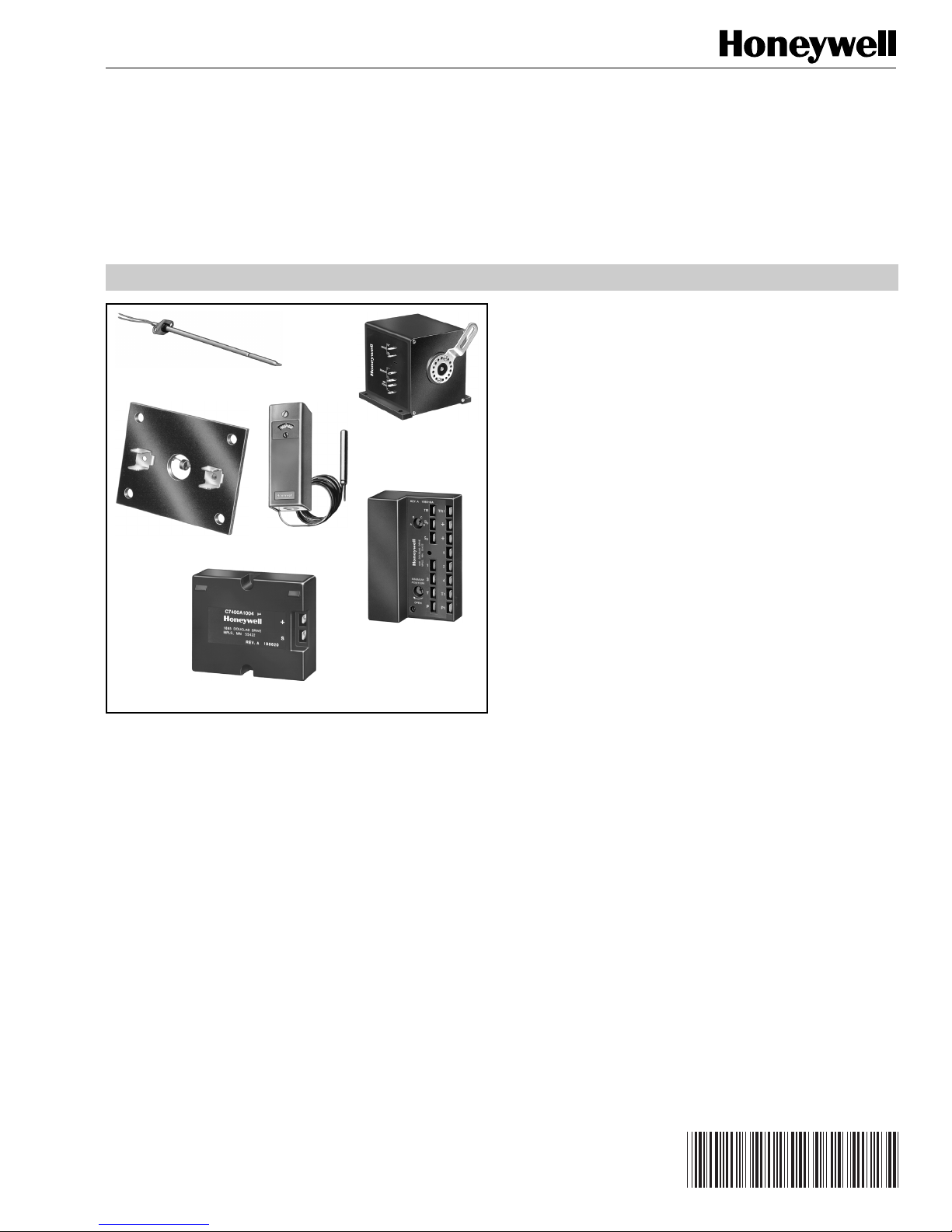
Solid State Economizer System
63-2484-1
(CONSISTING OF: C7046C DISCHARGE AIR SENSOR OR C7150B MIXED AIR SENSOR,
C7400A SOLID STATE ENTHALPY SENSOR OR C7650A SOLID STATE TEMPERATURE SENSOR,
M7415 OR M8405 DAMPER ACTUATORS, T6031H THERMOSTAT AND
W7459A,C, OR D SOLID STATE ECONOMIZER LOGIC MODULE)
PRODUCT DATA
FEATURES
C7046C Discharge Air Sensors have probe lengths of 8 in.
C7046C
M7415/M8405
C7150B
C7400A/C7650A
T6031H
W7459A,C,D
APPLICATION
The Solid State Economizer System provides an economical
method of providing cooling air by incorporating outdoor air in
the first stage of cooling in heating, ventilating and air
conditioning (HVAC) systems. The Solid State Economizer
System consists of the C7046C Discharge Air Sensor,
C7150B Mixed Air Sensor, C7400A Solid State Enthalpy
Sensor or C7650A Solid State Temperature Sensor, M7415
and M8405 Damper Actuators, T6031H Thermostat, and
W7459A,C,D Solid State Economizer Logic Module.
(203 mm) and nominal sensor resistance of 3000 ohms at
77°F (25°C).
• No setting or calibration required.
• Solid state components not affected by dust or dirt.
•Fast reacting.
• Rugged aluminum insertion probe.
C7150B Mixed Air Sensor is used with the M7415/M8405
Damper Actuator to sense mixed or discharged air in rooftop
packaged air conditioning equipment.
• No setting or calibration required.
C7400A Solid State Enthalpy Sensor and C7650A Solid State
Temperature Sensors are used with the W7459 Solid State
Economizer Logic Module to allow using outdoor air as the
first stage of cooling in HVAC systems.
• C7400A senses and combines temperature and
humidity of outdoor air (heat index).
• C7650A senses temperature only.
• Long-lasting, solid state sensing element is accurate
and stable over time.
• When enthalpy/temperature of outdoor air increases,
the outdoor air damper closes to a preset minimum
position.
• When enthalpy/temperature of outdoor air is low, the
outdoor air damper opens to reduce the building
cooling load.
•Provides a 4 to 20 mA output signal to the W7459 Solid
State Economizer Logic Module; setpoint is located on
solid state economizer control.
• Maximum economizer savings is achieved when two
C7400A Solid State Enthalpy Sensors are connected
to one W7459 Solid State Economizer Logic Module
for differential enthalpy changeover control.
(Continued)
® U.S. Registered Trademark
Copyright © 1997 Honeywell Inc. • All Rights Reserved
Contents
Application........................................................................... 1
Features .............................................................................. 1
Ordering Information ........................................................... 2
Specifications ...................................................................... 3
Installation ........................................................................... 7
Operation and Checkout ..................................................... 13
Settings and Adjustments ................................................... 15
Sequence of Operation ....................................................... 16
Checkout and Troubleshooting ............................................ 17
Page 2

SOLID STATE ECONOMIZER SYSTEM
M7415 and M8405 Damper Actuators are 25 lb-in. spring
return damper actuators that provide modulating or threeposition control of economizer systems, ventilation dampers
and combustion air dampers used in residential or
commercial HVAC equipment.
• M7415 Damper Actuator provides modulating
control of economizer dampers from a thermistor
mixed-air or discharge sensor to maintain 56°F
(13°C) air temperature.
• M8405A Damper Actuator provides three-position
control: closed, adjustable mid-position, and open.
• Quiet, high efficiency drive motor.
• High impact, glass-fiber reinforced, plastic case is
rugged, lightweight and corrosion resistant.
T6031H Thermostat acts as changeover thermostat.
• Switches enclosed to resist effects of dust and
moisture.
•Warmer-Cooler temperature scale.
• Sensing bulb installed in return air flow.
W7459A,C,D Solid State Economizer Logic Module used
with C7400 Solid State Enthalpy Sensors and M7415 or
M8405 Damper Actuators to proportion outdoor and
return air dampers for economizer control in commercial
HVAC equipment.
• Combine functions of solid state enthalpy changeover
control, minimum damper position potentiometer
(W7459A,D) and compressor staging relays.
• Optional differential enthalpy control provides greater
economizer savings than single enthalpy control by
selecting the most economical air for cooling.
Differential enthalpy control utilizes two sensor inputs:
one in return air and one in outdoor air; the
economizer control then determines which air has the
lower enthalpy.
• Solid state control package provides improved
accuracy, reliability and stability.
• W7459A,D mounts on M7415 Damper Actuator and
accepts inputs from C7150B Mixed Air Sensors,
C7400 Solid State Enthalpy Sensors, C7046C
Discharge Air Sensor, and optional remote minimum
damper position potentiometer.
• W7459C mounts on M8405A Damper Actuator and
accepts inputs from single pole single throw (spst)
mixed or discharge air control and C7400 Solid State
Enthalpy Sensors.
•Packages are designed to operate from the cooling
space thermostat to provide a totally integrated
control system.
• Housed in high-impact, glass-fiber reinforced plastic
case that matches the lines of M7415 and M8405
Damper Actuators.
• Quick connect terminals.
• Enthalpy setpoint (A,B,C,D) located on W7459 Solid
State Economizer Logic Module is used to select
combination of air temperature and humidity that is
suitable for free cooling.
• W7459A,D include built-in adjustable minimum damper
position potentiometer that controls the amount of
outdoor air admitted to meet minimum ventilation
requirements; include terminals for connecting
optional remote minimum position potentiometer.
• LED on W7459 indicates free cooling is available when
there is a call for cooling from the thermostat.
ORDERING INFORMATION
When purchasing replacement and modernization products from your TRADELINE® wholesaler or distributor, refer to the
TRADELINE® Catalog or price sheets for complete ordering number.
If you have additional questions, need further information, or would like to comment on our products or services, please write or
phone:
1. Your local Home and Building Control Sales Office (check white pages of your phone directory).
2. Home and Building Control Customer Relations
Honeywell, 1885 Douglas Drive North
Minneapolis, Minnesota 55422-4386
In Canada—Honeywell Limited/Honeywell Limitée, 35 Dynamic Drive, Scarborough, Ontario M1V 4Z9.
International Sales and Service Offices in all principal cities of the world. Manufacturing in Australia, Canada, Finland, France,
Germany, Japan, Mexico, Netherlands, Spain, Taiwan, United Kingdom, U.S.A.
63-2484—1
2
Page 3

SOLID STATE ECONOMIZER SYSTEM
SPECIFICATIONS
IMPORTANT
The specifications given in this publication do not
include normal manufacturing tolerances. Therefore,
these units may not exactly match the specifications
listed. Also, these products are tested and calibrated
under closely controlled conditions and some minor
differences in performance can be expected if these
conditions are changed.
Models:
Specifications for each model are listed separately.
C7046 Discharge Air Sensors
Intended for use as a discharge sensor in rooftop
applications.
Sensing Element:
Carbon type, thermistor-resistor element.
Performance Characteristics:
Reaction Time Constant with Air Approach Velocity of
8.33 ft/sec (2.54 m/sec): 60 seconds.
Resistance/Temperature (NTC):
Nominal Resistance: 3000 ohms at 77°F (24°C).
Nominal Sensitivity: 70 ohms per degree F (124 ohms per
degree C) at midrange.
Maximum Ambient Temperature:
250°F (121°C).
Operating Temperature Range:
-40°F to +110°F (-40°C to +44°C).
Dimensions:
See Fig. 2.
C7400A Solid State Enthalpy Sensor/C7650A Solid
State Temperature Sensor
Permits use of outdoor air as the first stage of cooling in
HVAC systems.
Temperature Sensing Element:
Thermistor.
Output Signal:
4 to 20 mA current signal; increases from 4 mA to 20 mA as
enthalpy decreases.
Ambient Operating Temperature Range:
-40°F to +125°F (-40°C to +52°C).
3/4
(19)
Mounting Arrangement:
Integral mounting flange that requires two no. 8 screws
(not provided).
Maximum Ambient Temperature:
250°F (121°C).
Operating Temperature Range:
40°F to 150°F (4°C to 66°C).
Wiring Connections:
6 in. (152 mm) leadwires.
Dimensions:
See Fig. 1.
C7150B Mixed/Discharge Air Sensor
Used to sense mixed or discharged air in rooftop packaged
air conditioning equipment.
Resistance/Temperature (NTC):
Nominal Resistance: 3000 ohms at 77°F (24°C).
Nominal Sensitivity: 70 ohms per degree F (124 ohms per
degree C) at midrange.
7/8
(22)
3/16 (5) DIAMETER
2
(51)
2-1/2 (64)
M9084
Fig. 2. Approximate dimensions of C7150B Mixed/
Discharge Air Sensor in in. (mm).
1/2 (13)
DIAMETER
3/8 (10)
DIAMETER
1/4 (6)
DIAMETER
(2)
3/4 (19)
1-1/2 (38)
Fig. 1. Approximate dimensions of C7046C Air Temperature Sensor in in. (mm).
9/16
(14)
IMMERSION LENGTH: 8 (203)
M9087
3
63-2484—1
Page 4
SOLID STATE ECONOMIZER SYSTEM
Approval:
Underwriters Laboratories Inc. Flammability Rating:
UL94-5V.
Dimensions:
See Fig. 3.
5/16 (8)
9/16
(14)
1 (25)
3-5/32
(80)
2-3/4
(70)
7/32
(6)
3-7/8 (96)
+
S
M9096
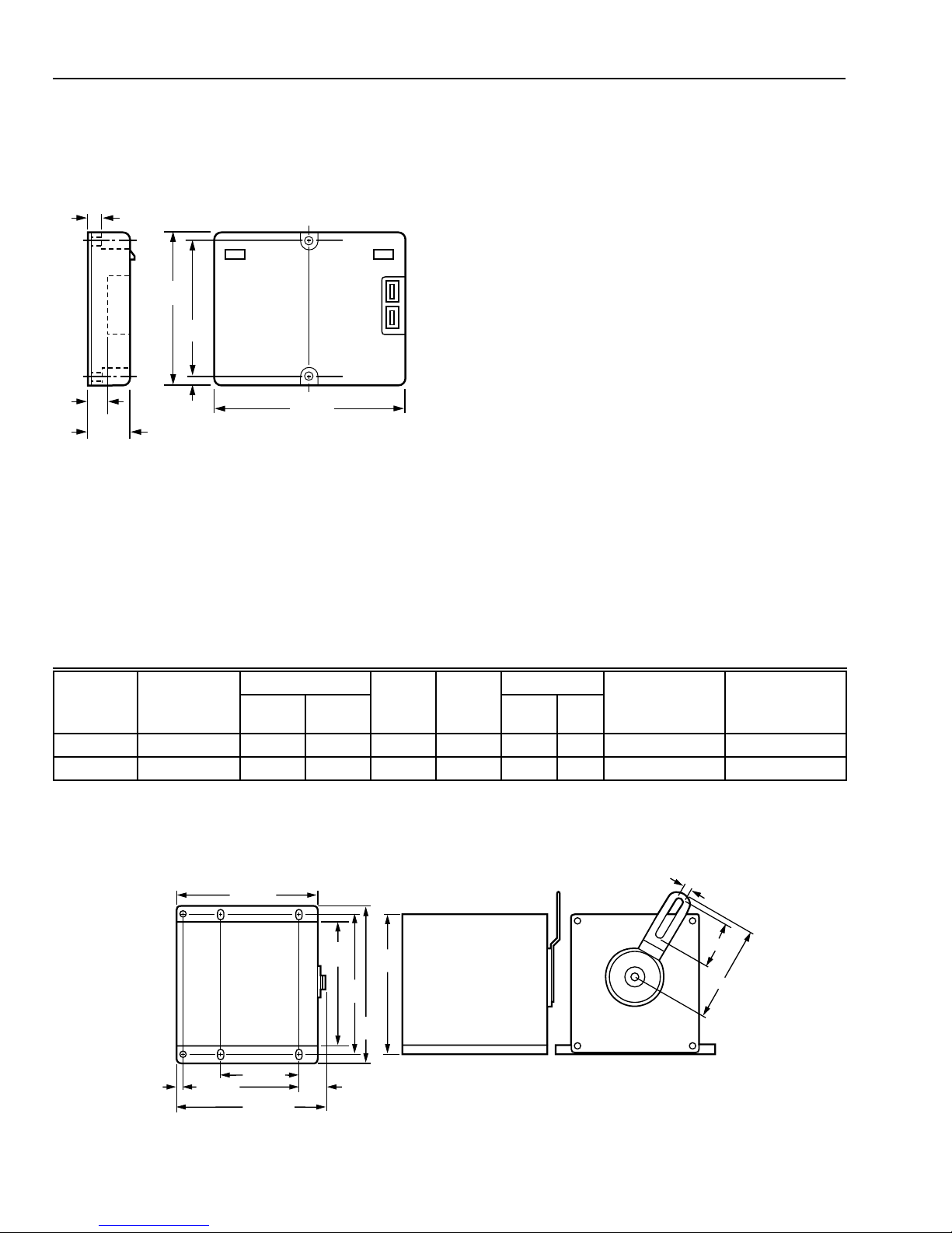
Fig. 3. Approximate dimensions of C7400A Solid State
Enthalpy Sensor/C7650A Solid State
Temperature Sensor in in. (mm).
M7415A, M8405A Damper Actuators
Provides control of economizer systems, ventilation dampers
and combustion air dampers used in residential or
commercial HVAC equipment.
Actuator Rotation:
Closed position is the limit of clockwise rotation; open position
is the limit of counterclockwise rotation as viewed from the
shaft end of the motor. These motors are shipped with the
shaft in the closed position.
Auxiliary Switch Rating (M8405A only):
24 Vac, 20 VA inrush, 20 VA run (R8222 or equivalent load).
Terminal Connections:
1/4 in. (6 mm) male quick connect terminals mounted on
actuator. Terminal arrangement is dependent on actuator
model.
Ambient Operating Temperature Range:
-40°F to +125°F (-40°C to +52°C).
Voltage and Timing:
See Table 1.
Dimensions:
See Fig. 4.
Shaft:
Single-ended drive shaft with crank arm supplied.
Flammability Rating:
Underwriters Laboratories Inc. UL94-5V.
Approval:
Underwriters Laboratories Inc.
Component Recognized: File No. E4436, Guide No. XAPX2,
Vol. 9, Section 1, 7-25-83.
Table 1. M7415A/M7405A Actuator Specifications.
Power (Vac) Torque
Model
Number
M7415A
M8405A
a
Timing with 60 Hz power.
b
Spring return.
c
Modulating.
d
Three-position with field adjustable minimum position control.
Voltage (Vac)
50/60 Hz (Drive) (Hold)
b,c
24 8 5 90 90 25 2.8 ccw cw
b,d
24 7 3 90 90 25 2.8 ccw cw
4-1/2 (114)
4-1/32
(102)
7/16
(11)
3-1/2 (89)
2-1/4 (57)
5-3/16 (132)
1-1/4
(32)
4-1/2
(114)
(127)
5
Timing
(sec)
4-1/2
(114)
Stroke
a
(°) (lb-in.) (N•m)
Open Rotation
(Shaft End View)
1/4 (6)
1-3/8 (35)
3-1/8 (79)
Spring Return
(Shaft End View)
M3851TOP VIEW SIDE VIEW POWER END VIEW
Fig. 4. Approximate dimensions of M7415A and M8405A in in. (mm).
63-2484—1
4
Page 5
SOLID STATE ECONOMIZER SYSTEM
M9085A
2-3/16
(56)
4-1/16
(103)
7/8 (22)
5/8
(16)
2-13/16 (71)
1-1/4
(32)
T6031H Thermostat
A standard spdt switch, without a case, that acts as a
changeover thermostat.
Electrical Rating:
0.25A at 1/.4V to 12 Vdc inductive load.
Control Range, Element Temperature and Differential:
See Table 2.
Approval:
Underwriters Laboratories Inc. Listed:
File E4436, Vol. 4, Guide No. XAPX2.
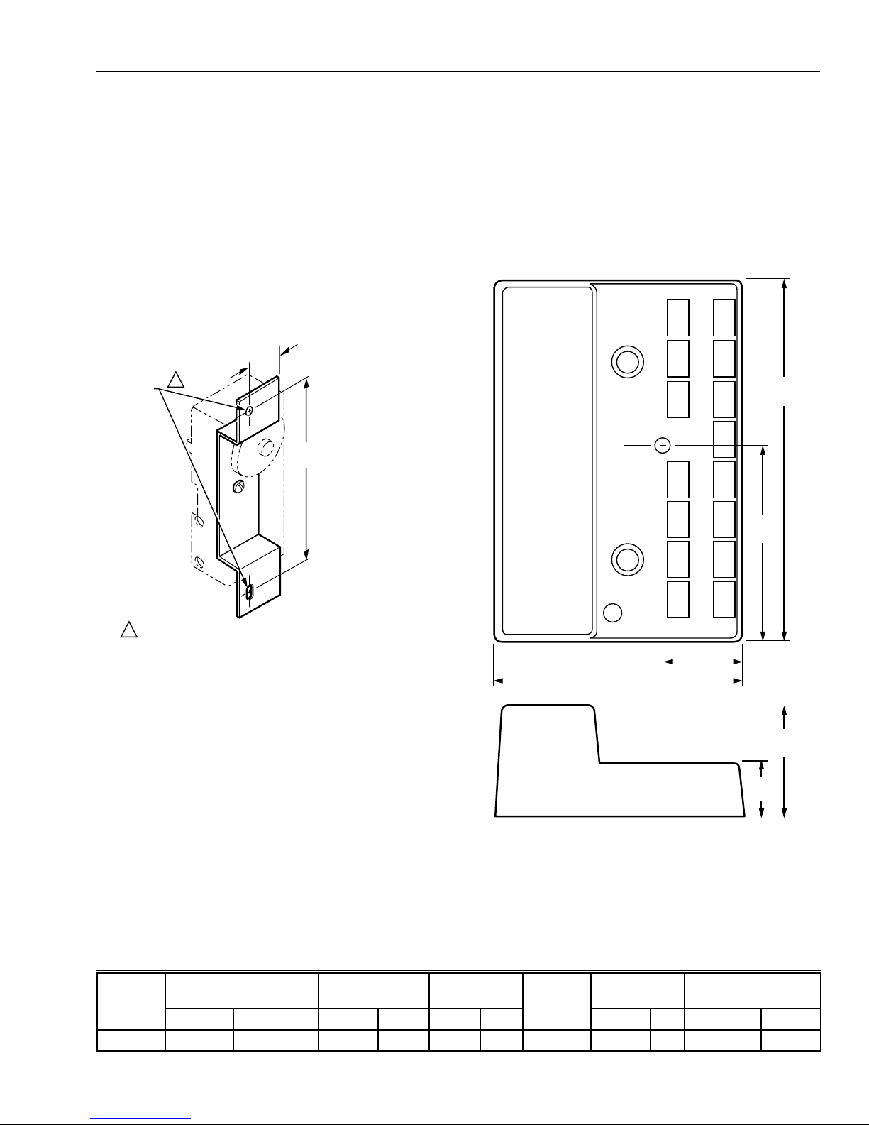
Dimensions:
See Fig. 5.
MOUNTING
HOLES
1
3/4 (19)
4-3/16
(106)
Temperature Ratings:
-25°F to +125°F (-32°C to +52°·C).
Approval:
Underwriters Laboratories Inc.:
Flammability Rating: UL94V-5V.
Specifications:
See Table 3.
Dimensions:
See Fig. 6.
OVERALL LENGTH: 5 (127)
OVERALL DEPTH LESS
ADJUSTING DIAL SHAFT:
2-1/8 (54)
ON THE 114496 BRACKET, THE MOUNTING HOLES ARE TWO
1
NO. 8-32 TAPPED HOLES. THE 107940 BRACKET IS MOUNTED
WITH A 5/32 (4) DIAMETER HOLE AT THE TOP AND A VERTICAL
5/32 X 5/16 (4 X 8) SLOT AT THE BOTTOM.
Fig. 5. Approximate dimensions of back mounting
M9090
bracket for T6031H in in. (mm).
W7459A,C,D Solid State Economizer Logic Module
Used with C7400 Sensor or C7650A Sensor and M7415 or
M8405 Actuator to proportion outdoor and return air
dampers for economizer control in commercial HVAC
equipment. Do
enthalpy limit devices.
Electrical Ratings:
Input Voltage: 24 Vac, 50/60 Hz.
Power Consumption: 5.5 VA.
Relay Contact Rating at 24 Vac: 1.5A run, 3.5A inrush.
Model
Number
T6031H 0° to 95° -18° to +35° 150° 66° 3° 2° Back 2 0.6 3/8 x 3-1/2 10 x 89
not
use C7650A Sensor with W7459D high
Table 2. T6031H Thermostat Specifications.
Control
Range
°F °C °F °C °F °C
Max Element
Temperature Differential
Fig. 6. Approximate dimensions of W7459 Solid State
Economizer Logic Module in in. (mm).
Capillary
Type of
Mounting
Length Bulb Size
ft m in. mm
5
63-2484—1
Page 6
SOLID STATE ECONOMIZER SYSTEM
Table 3. W7459A,C,D Specifications.
For Use with
Model
Actuator
W7459A M7415 Thermistor Sensor Yes Yes 2 spdt
W7459C M8405 Spst control No. Minimum position
W7459DaM7415 Thermistor Sensor
a
W7459D has a high enthalpy limit and defaults to mechanical cooling when the outdoor enthalpy reaches the preset limit.
Do not use a dry bulb sensor for a high temperature limit.
Discharge Air
Temperature Input
C7150B or C7046A
Minimum Position
Potentiometer Adjustment
Terminals for Remote
Minimum Damper Position
Output
Relays
No 2 spdt
adjustment is built into
M8405 Actuator
Yes Yes 2 spdt
INSTALLATION
When Installing these Products…
1. Read these instructions carefully. Failure to follow them
could damage the product or cause a hazardous
condition.
2. Check the ratings given in the instructions and marked
on the product to make sure the product is suitable for
your application.
3. Installer must be a trained, experienced service
technician.
4. After installation is complete, check out the product
operation as provided in these instructions.
CAUTION
CAN CAUSE ELECTRICAL SHOCK OR
EQUIPMENT DAMAGE.
Disconnect power supply before connecting wiring.
C7046C Discharge Air Temperature Sensor
The sensor assembly consists of an aluminum sensor
probe (element housed internally) with attached flange that
can be mounted on a flat duct or plenum surface, or in a
2 in. by 4 in. (51 by 102 mm) junction box, using two no. 8
screws. Connections to the sensor are made through two
6 in. (152 mm) leadwires.
쐋 If necessary, use the flange as a template to mark and
drill two holes for no. 8 mounting screws.
쐏 Fasten the sensor to the duct or plenum surface with
the two no. 8 sheet metal screws (not provided).
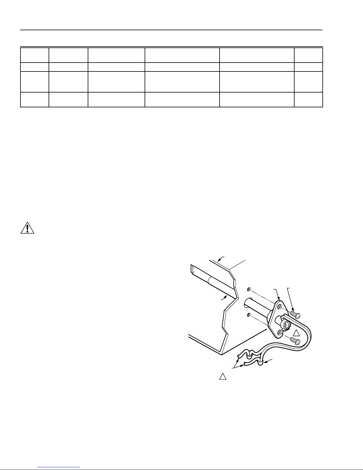
To mount the C7046C Sensor in a junction box (see Fig. 8):
쐃 Cut a 1/2 in (13 mm) hole in the duct or plenum surface
at the desired location.
쐇 Remove the center rear knockout from the junction box
and insert the sensor probe through the knockout with
the flange flat against the junction box.
쐋 Using the flange as a template, mark and drill two holes
in the junction box and the duct or plenum surface for
no. 8 mounting screws.
쐏 Insert the sensor probe through both the junction box
knockout and the 1/2 in. (13 mm) hole drilled in the duct
or plenum and fasten the junction box and sensor to the
duct or plenum surface with the two no. 8 sheet metal
screws (not provided).
SYSTEM DUCT OR PLENUM
FLANGE
SENSOR PROBE
NO. 8
MOUNTING
SCREWS (2)
Location
Locate the sensor in the air duct or plenum where it can
sample average air temperature. Avoid locations where air
stratification can cause sensing errors.
Mounting
To mount the C7046C Sensor on a flat duct or plenum
surface (see Fig. 7):
쐃 Cut a 1/2 in (13 mm) hole in the duct or plenum surface
at the desired location.
쐇 Insert the sensor probe into the duct or plenum hole
until the flange rests against the duct or plenum wall.
63-2484—1
1
TO APPROPRIATE
SYSTEM COMPONENTS
(SEE WIRING DIAGRAM)
SCREWS NOT PROVIDED.1
SENSOR WIRES WITH
2 SOLDERLESS
CONNECTORS
M9086
Fig. 7. Mounting C7046C Air Temperature
Sensor on duct or plenum.
6
Page 7

CONNECTOR
AND
LOCKNUT
TO APPROPRIATE
SYSTEM COMPONENTS
(SEE WIRING DIAGRAM)
STANDARD 2 X 4 (51 X 102)
OUTLET BOX (OPTIONAL)
SENSOR PROBE
SENSOR WIRES WITH 2
SOLDERLESS CONNECTORS
SOLID STATE ECONOMIZER SYSTEM
FLANGE
BLANK
FACEPLATE
(OPTIONAL)
1
Wiring
IMPORTANT
Failure to follow these wiring practices can introduce
electrical interference (noise) that can cause erratic
system operation:
a. Keep wiring at least one foot away from large
b. Shielded cable is required in installations where
c. Ground shield only to grounded controller case.
IMPORTANT
Minimize erratic temperature readings from a
sensor to assure proper operation by following
these wiring practices:
a. Route temperature sensor wiring away from
b. Make good physical wiring connections to assure
c. Make sure that building earth ground connections
d. Mount sensor only in recommended environment.
e. Use shielded cable to reduce interference if
M9088
SYSTEM DUCT OR PLENUM
Fig. 8. Mounting C7046C Discharge Air Temperature Sensor in junction box.
inductive loads such as motors, line starters,
lighting ballasts, and large power distribution
panels.
these guidelines cannot be met.
building power wiring, control contactors and
light dimming circuits, electric motors and
welding equipment.
good electrical connections.
are not intermittent or missing.
rerouting of sensor wiring is not possible.
SCREWS NOT PROVIDED.1
CAUTION
CAN CAUSE ELECTRICAL SHOCK OR
EQUIPMENT DAMAGE.
Disconnect the power supply before connecting the
wiring.
Make sure wiring complies with applicable local
codes, ordinances and regulations.
Connect low voltage wiring from the sensor to the appropriate
system component terminals using solderless connectors as
shown in Fig. 7 and 8.
M7415A, M8405A Damper Actuators
CAUTION
CAN CAUSE ELECTRICAL SHOCK OR
EQUIPMENT DAMAGE.
Disconnect power supply before connecting wiring.
WARNING
CAN CAUSE PERSONAL INJURY.
Do not remove end covers from actuator; spring
return assembly can release to harm installer.
7
63-2484—1
Page 8

SOLID STATE ECONOMIZER SYSTEM
Location and Mounting
Location
Locate the actuator as close as possible to the equipment to
be controlled. Refer to Fig. 4 for mounting dimensions.
Mounting
Mount the actuator with the shaft horizontal to assure
maximum life; however, operation in other positions is
possible when required in specific applications.
Remove the crank arm from the actuator (secured with
two screws) and reposition to accommodate specific damper
requirements. The crank arm position can be adjusted in
7.5-degree increments.
IMPORTANT
Position crank arm on actuator hub so that it does
not strike the actuator mounting surface during any
portion of the full stroke. See Fig. 9.
Disconnect power supply before connecting wiring to prevent
electrical shock or equipment damage. All wiring must comply
with applicable local codes and ordinances. See Fig. 10 and
13 for typical hookup diagrams.
T6031H Thermostat
Location and Mounting
The T6031H Thermostat mounts either vertically or
horizontally on a wall or panel. Locate the remote bulb as far
from the controller as capillary tubing allows. Locate the
bulb where it can sense the average temperature of the
controlled medium.
Mounting Sensing Elements
T6031H: Install the bulb in the return airflow where air of
average temperature can circulate around it.
IMPORTANT
Do not overtighten clamps to the point of distorting
the sensor bulb because overtightening causes a
significant shift in bulb calibration.
Mounting Thermostat
Mount the thermostat using the back mounting plate as
shown in Fig. 5.
Wiring
MAXIMUM
OPEN
POSITION
MOTOR MOUNTING SURFACE
CRANK ARM FIELD ADJUSTABLE IN 7.5 DEGREE INCREMENTS.
1
Fig. 9. Limits of crank arm rotation.
1
Wiring
CAUTION
CAN CAUSE ELECTRICAL SHOCK OR
EQUIPMENT DAMAGE.
Disconnect power supply before connecting wiring.
MAXIMUM
CLOSED
POSITION
M3850
CAUTION
CAN CAUSE ELECTRICAL SHOCK OR
EQUIPMENT DAMAGE.
Disconnect power supply before connecting wiring.
Disconnect the power supply before connecting wiring to
prevent electrical shock and equipment damage. All wiring
must comply with applicable local codes and ordinances.
Refer to Fig. 11 and the wiring diagrams furnished with the
system equipment to complete the wiring.
63-2484—1
8
Page 9

SOLID STATE ECONOMIZER SYSTEM
M8405
T
APPLY
24VAC T-X
FOR MIN POSN
T-D FOR
MAX POSN
X
D
W7459C ECONOMIZER PACKAGE
M8405 ACTUATOR
T
MAX
SW
SET
MIN
+
OUTDOOR
SENSOR
TR TR1
SO
+
S
C7400
S
RETURN
SENSOR
+
C7400
UNOCCUPIED
S6005
TIMER
OCCUPIED
T675/T6031 MIXED
AIR CONTROL
55° F SETPOINT
W
R
SR
+
5
1K
1
2
4
3
X
6
D
4
2K
X
D
C
Y1
Y2
W2
W
T6031 AMBIENT
R
LOCKOUT CONTROL
50° F SETPOINT
Y1
Y2
W2
COOL 1
COOL 2
HEAT 2
2
HEAT 1
FAN
DELAY
RELAY
FAN
1
W1
W1
G
FDR
G
RH
RC
T7300 OR T874
THERMOSTAT
POWER SUPPLY. PROVIDE DISCONNECT MEANS AND OVERLOAD PROTECTION AS REQUIRED.
1
2
MOTOR SPRING-RETURNS CLOSED WHEN FAN IS NOT RUNNING.
ASSURE THAT EQUIPMENT TRANSFORMER IS SIZED FOR THE EXTRA LOAD OF THE ECONOMIZER AND ACTUATOR.
3
RELAYS 1K AND 2K ACTUATE WHEN THE ENTHALPY SENSED BY THE C7400 IS HIGHER THAN THE ENTHALPY SETPOINT A-D.
4
FACTORY INSTALLED 620 OHM, 1 WATT, 5% RESISTOR SHOULD BE REMOVED ONLY IF A C7400 ENTHALPY SENSOR
5
IS ADDED TO SR AND + FOR DIFFERENTIAL ENTHALPY.
HVAC EQUIPMENT
TERMINAL STRIP
FDR
R
Fig. 10. M8405A Damper Actuator used in two-stage cooling system with differential enthalpy
changeover and W7459C Economizer.
3
L2
L1
(HOT)
M3865A
9
63-2484—1
Page 10

SOLID STATE ECONOMIZER SYSTEM
TEMPERATURE
RISE
M7415, M7405 OR
M8405 ACTUATOR
SETPOINT
SWITCH
DIFFERENTIAL
SETPOINT
W
B
R
FOR T6031H
R AND W LOCATIONS
DEPEND ON MODEL
AND CONSTRUCTION
BREAKS R-B;
MAKES R-W
ON RISE
MAKES R-B;
BREAKS R-W
ON FALL
M9089
Fig. 11. T6031H switch terminal
arrangement and switching.
C7400 Enthalpy Sensor and C7650 A
W7459A,C,D Solid State Economizer Logic
Module
CAUTION
CAN CAUSE ELECTRICAL SHOCK OR
EQUIPMENT DAMAGE.
Disconnect power supply before connecting wiring.
Location and Mounting
W7459 Economizer Logic Module
Mount the W7459 Economizer Logic Module on the side of
the M7415 or M8405 Damper Actuator. When planning the
installation, allow enough clearance for maintenance and
service. Install the W7459 Economizer Logic Module where it
is protected from rain and snow. One mounting screw is
supplied to secure the W7459 to the actuator (after the
actuator is mounted). See Fig. 12.
Temperature Sensor
Location and Mounting
Outdoor air sensing: Mount the C7400 Enthalpy Sensor or
C7650A Temperature Sensor in any orientation where it is
exposed to freely circulating air but protected from rain, snow
and direct sunlight.
Return air sensing: For differential enthalpy or temperature
control, a second C7400 Enthalpy Sensor or C7650A
Temperature Sensor is connected to the W7459. Mount the
second sensor in the return air duct as far as possible from
the outdoor air sensor.
Wiring
W7459
ECONOMIZER PACKAGE
M9091
Fig. 12. Mounting W7459 on M7415 or
M8405 Damper Actuator.
CAUTION
CAN CAUSE ELECTRICAL SHOCK OR
EQUIPMENT DAMAGE.
Disconnect power supply before connecting wiring.
63-2484—1
Disconnect the power supply before connecting wiring to
prevent electrical shock or equipment damage. All wiring
must comply with applicable local codes, ordinances and
regulations. See Fig. 13 for a typical wiring diagram.
10
Page 11

TR TR1
SOLID STATE ECONOMIZER SYSTEM
M7415 ACTUATORW7459A ECONOMIZER PACKAGE
TR
24 VAC
TR1
UNOCCUPIED
OCCUPIED
1
2
3
4
5
6
OUTDOOR
AIR
ENTHALPY
SENSOR
C7400
620 OHM
RESISTOR
C7150B MIXED
AIR OR
C7046A
S6005
TIMER
POWER SUPPLY. PROVIDE DISCONNECT MEANS AND OVERLOAD PROTECTION AS REQUIRED.
MOTOR SPRING-RETURNS CLOSED WHEN FAN IS NOT RUNNING.
ASSURE THAT EQUIPMENT TRANSFORMER IS SIZED FOR THE EXTRA LOAD OF THE ECONOMIZER AND ACTUATOR.
1S IS AN ELECTRONIC SWITCH, WHICH CLOSES WHEN POWERED BY A 24 VAC INPUT.
RELAYS 1K AND 2K ACTUATE WHEN THE ENTHALPY SENSED BY THE C7400 IS HIGHER THAN THE ENTHALPY SETPOINT A-D.
FACTORY INSTALLED 620 OHM, 1 WATT, 5% RESISTOR SHOULD BE REMOVED ONLY IF A C7400 ENTHALPY SENSOR
IS ADDED TO SR AND + FOR DIFFERENTIAL ENTHALPY.
DISCHARGE
AIR SENSOR
Y1
Y2
W2
W1
G
RH
RC
T7300 OR T874
THERMOSTAT
+
S
W
T6031 AMBIENT
LOCKOUT
R
CONTROL
50° F SETPOINT
+
S
O
S
R
1
3
T
P
6
+
5
1K
2
4
T1
P1
5
2K
MINIMUM POSITION
ADJUSTMENT
C
Y1
Y2
W2
W1
G
R
HVAC EQUIPMENT
TERMINAL STRIP
1S
1S1
FDR
FDR
4
COOL 1
COOL 2
HEAT 2
HEAT 1
FAN
DELAY
RELAY
FAN
2
T
T1
P1
P
MIXED
AIR
SENSOR
MINIMUM
POSITION
24 VAC
SENSOR
1
L2
L1
(HOT)
MIN
POS
3
M10115
M7415
TR
TR1
T
T1
P1
P
Fig. 13. W7459A,D/C7400 used in two-stage cooling system with single enthalpy changeover and with M7415 Actuator.
11
63-2484—1
Page 12

SOLID STATE ECONOMIZER SYSTEM
OPERATION AND CHECKOUT
Operation
Controller Dial Setting
Control setpoint scale is located on the W7459 Solid State
Economizer Logic Module. Control points A, B, C, and D are
field selectable; A, B, C, D control points are used for single
enthalpy or temperature sensing. One enthalpy or temperature
sensor is connected to the solid state economizer control for
single enthalpy or temperature. Turn D (fully clockwise )
when the differential enthalpy or temperature control is desired.
Tw o enthalpy or temperature sensors are connected to the
solid state economizer control for differential enthalpy control.
See Fig. 10 and 13.
IMPORTANT
Do not use C7650A Solid State Temperature
Sensors with W7459D high enthalpy limit devices.
C7046C and C7150B Mixed/Discharge Air Sensors
The C7046C and C7150B Mixed Air Sensors consist of a
thermistor sensing element mounted in a tubular probe. The
sensors are applied at various locations throughout single
zone and multizone duct systems. The negative temperature
coefficient (NTC) characteristic of the thermistor element
causes its resistance to decrease as the sampled air
temperature increases. See Fig 14. To stabilize system
control, the resistance shift is balanced with other system
sensor signals by appropriate system logic panels.
4500
4000
3500
3,000 OHMS AT
3000
2500
RESISTANCE (OHMS)
2000
1500
77°F (25°C)
C7400A Solid State Enthalpy Sensor
The C7400A Solid State Enthalpy Sensor is used with a solid
state economizer control and damper actuator to proportion
an outdoor air damper in a ventilation system.
Figure 15 is a partial psychometric chart with single C7400A
Sensor and W7459A Economizer Logic Module performance
curves. The curves illustrate the reset in the temperature
control point due to changes in relative humidity.
The enthalpy control setpoint A,B,C, or D combines
temperature and humidity conditions, resulting in the control
curve shown in Fig. 15. When the enthalpy or outdoor air is
below (left of) the appropriate curve, the outdoor air damper
can proportion open on a call for cooling. If outdoor air
enthalpy rises above (to the right of) the control curve, the
outdoor air damper closes to the minimum position.
For differential enthalpy, turn the control setpoint to D (fully
clockwise). If outdoor air enthalpy is lower than return air
enthalpy, the outdoor air damper proportions open on a call
for cooling.
If outdoor air enthalpy is higher than return air enthalpy, the
outdoor air damper closes to minimum position. Differential
enthalpy control provides energy savings and increased
comfort by using the air with the lowest enthalpy.
If outdoor air enthalpy and return air enthalpy are equal, the
outdoor air damper proportions open on a call for cooling.
The relationship between the C7400A Sensor output current
and relative humidity is shown in Fig. 16.
C7650A Solid State Temperature Sensor
The C7650A Solid State Temperature Sensor is used with a
solid state economizer control and damper actuator to
proportion an outdoor air damper in a ventilation system.
When outdoor air temperature is higher than return air
temperature, the outdoor air damper closes to the minimum
position. When the outdoor air temperature and the return air
temperature are equal, the outdoor air damper proportions
open on a call for cooling.
The relationship between the C7650A Sensor output current
and the air temperature is shown in Fig. 17.
1000
60 65 70 75 80 85 90 95 100
55
20
15
25
TEMPERATURE (DEGREES)
30 35
Fig. 14. C7046C and C7150B Air Temperature Sensors
resistance versus temperature.
63-2484—1
F
C
M9099
12
Page 13

SOLID STATE ECONOMIZER SYSTEM
40
45 50 55
60 65
70 75 80 85 90
95
100
19
18
17
16
15
14
13
12
11
10
9
LED OFF
LED OFF
LED OFF
LED OFF
LED ON
LED ON
LED ON
LED ON
D
C
B
A
mA
°F
NOTE: A,B,C,D ARE W7459 SWITCHING SETPOINTS.
M7578A
85
(29)90(32)95(35)
CONTROL
CURVE
12 14 16 18 20 22 24 26 28 30 32 34 36 38 40 42
A
B
C
D
CONTROL POINT
APPROX. °F (°C)
AT 50% RH
73 (23)
70 (21)
67 (19)
63 (17)
ENTHALPY—BTU PER POUND DRY AIR
60
(16)
55
(13)
B
50
C
(10)
45
D
(7)
40
(4)
35
(2)
44 46
80
(27)
75
(24)
70
(21)
100
90
65
(18)
A
80
70
60
50
40
100
(38)
RELATIVE HUMIDITY (%)
30
0
2
105
(41)
110
(43)
10
1
HIGH LIMIT CURVE FOR W6210D,W7210D,W7459D.
Fig. 15. Partial psychrometric chart with single C7400A Solid State Enthalpy Sensor and
W7459 Solid State Economizer Logic Module performance curves.
100
90
80
70
60
50
PERCENT RH
40
30
20
10
(4) (10) (16) (21) (27) (32) (38)
Fig. 16. C7400A Sensor output current vs.
C7400A OUTPUT CURRENT
16 mA
18 mA
20 mA
605040 70 80 90 100
TEMPERATURE °F (°C)
relative humidity.
14 mA
12 m
A
10 mA
B
C
D
35
40
45
50
55
60
65
70
75
(2)
(4)
(7)
(10)
(13)
(16)
(18)
(21)
(24)
80
(27)
APPROXIMATE DRY BULB TEMPERATURE—°F (°C)
6 mA
4 mA
8 mA
M9101
Fig. 17. C7650A Solid State Temperature Sensor output
13
1
A
85
(29)90(32)95(35)
100
(38)
105
(41)
M11160
current vs. temperature.
110
(43)
63-2484—1
Page 14

SOLID STATE ECONOMIZER SYSTEM
M7415 Damper Actuator
Single M7415 Damper Actuator accepts thermistor sensor
input from a C7046A or a C7150B Mixed Air Sensor mounted
in discharge or mixed air duct. See Fig. 13.
During the occupied period, on a call for cooling, when
outdoor air temperature or enthalpy conditions are low, the
M7415 Actuator proportions to maintain between 50°F (10°C)
and 56°F (13°C) at the thermistor sensor.
If the mixed or discharge temperature is above 56°F (13°C),
the M7415 Actuator opens to admit additional outdoor air until
the temperature returns to the 50°F (10°C) to 56°F (13°C)
range. If the mixed or discharge air temperature is below
50°F (10°C), the actuator proportions closed, shutting the
outdoor air damper until the temperature returns to the 50°F
(10°C) to 56°F (13°C) range. During the occupied period, the
actuator does not close past the minimum position.
If the fully open M7415 Actuator cannot satisfy the space
demand, mechanical cooling is sequenced on.
During the unoccupied period, the M7415 Actuator overrides
the minimum position setting and drives fully closed. On a
loss of power, the actuator spring-returns fully closed.
The M7415 Actuator can also accept the Q769A 6- to 9-volt
Adapter. The Q769A is factory calibrated so that the motor
drives open from the closed position at 6.2 Vdc. A nominal
M7415 Actuator drives closed from the open position at 8.8 Vdc.
Sensor. It responds to both dry bulb temperature and
humidity, allowing the use of outdoor air at higher
temperatures for free cooling when the humidity is low.
The economizer functions as a true first stage of cooling and
provides maximum fuel economy during the cooling cycle.
The economizer is automatically locked out during heating. It
holds the outdoor air damper at the minimum position setting.
On a call for cooling by the space thermostat, the system
operates as follows:
When the enthalpy or temperature of the outdoor air is below
the setpoint, the outdoor air damper is proportioned open
(and the return air damper is proportioned closed) to maintain
between 50°F and 56°F (10°C and 13°C) at the mixed/
discharge air sensor. During economizer operation, the
mechanical cooling is operated by stage 2 cooling on the
space thermostat.
When the enthalpy or temperature of the outdoor air is above
the setpoint, the outdoor air damper closes to its minimum
position. A call for cooling from the space thermostat turns on
the mechanical cooling.
During the unoccupied period, the M7415 Damper Actuator
spring-returns the outdoor air damper to the fully closed position.
SETTINGS AND ADJUSTMENTS
If terminals P and P1 are jumpered, the M7415 drives fully
open; however, if terminals P and P1 are left open, the
M7415 drives fully closed. The M7415 minimum position
adjustment drives the motor open when the resistance across
P and P1 is minimal. Increasing the amount of resistance
across these terminals drives the actuator closed.
M8405 Damper Actuator
An spst low voltage controller is used to control the M8405
Actuator as follows:
a. Fully open—when the controller circuit closes to
provide 24 Vac to terminals D and T, the actuator
is energized and runs fully open.
b. Fully closed—when the controller circuit opens,
power is removed from terminals D and T, and the
actuator spring returns to the fully closed position.
c. Mid-position—when the controller circuit closes to
provide 24 Vac to terminals T and X, the actuator
is energized to run to the adjustable mid-position
(minimum position).
Adjustable minimum position can be reached from either the
fully closed or fully open position. From fully closed, the
actuator drives open to the minimum position; from fully open,
the actuator spring-returns to minimum position.
W7459A,C,D Solid State Economizer Logic Module
The purpose of an economizer is to use outdoor air for
cooling, whenever possible, to reduce air conditioner
compressor operation. The W7459 Economizer System,
when wired as shown in Fig. 10 or 13, responds to a signal
from the cooling thermostat. This system uses a C7400 Solid
State Enthalpy Sensor or a C7650A Solid State Temperature
Adjusting Minimum Damper Position
The minimum position potentiometer keeps the outdoor air
damper from completely closing during system operation to
allow ventilation.
M7415 and M8405 Damper Actuators
Adjusting Minimum Position (Ventilation)
The M7415 Damper Actuator is adjusted for desired minimum
position using a Q709 Actuator Mounted Minimum Position
Potentiometer and/or a remote S963B1136 Manual
Potentiometer. The M8405 Damper Actuator has an integral
thumbwheel for minimum position adjustment.
M7415 Minimum Position Adjustment
쐃 Run actuator to fully closed position and disconnect
쐇 Connect minimum position potentiometer to terminals P
쐋 Reconnect 24 Vac to terminals TR and TR1 and adjust
쐏 When the Q709 Actuator Mounted Minimum Position
M8405 Minimum Position Adjustment
쐃 Connect the 24 Vac to the actuator at terminals T and X
쐇 Adjust the thumbwheel on the actuator for desired
24 Vac from terminals TR and TR1.
and P1 (T and T1 are disconnected).
the potentiometer for the desired minimum position.
Potentiometer is used and a remote potentiometer is
not connected in series, jumper terminals P and P1 on
the Q709A.
(D is not connected).
minimum position.
63-2484—1
14
Page 15

SOLID STATE ECONOMIZER SYSTEM
Discharge Air Temperature Setpoint
W7459C Economizer Logic Module
쐃 Connect 24 Vac at terminals TR and X (D is not
Adjustment—M7415 Only
This temperature range can be adjusted either up or down by
wiring a resistor in series (to increase the setpoint) or in parallel
(to decrease the setpoint) with the C7150B, depending on the
application. See Fig. 18 and 19 for explanation.
R
C7150
RESISTOR VALUE (OHMS)
USE 1%, 1/8 W OR HIGHER RESISTOR
681
2760
3650
4420
4750
4870
NO RESISTOR
T
T1
M7415
C7150B SETPOINT °F (°C)
54.5—61.5 (12.5—16.4)
68.4—80.1 (20.3—26.8)
87.4—110.3 (30.8—45.5)
104.7—150 (40.4—65.5)
116—194 (46.7—90)
120—300 (49—149)
50—56 (10—13.3)
M1544C
Fig. 18. Increasing C7150B setpoint.
T
R
C7150
RESISTOR VALUE (OHMS)
18.2K
24K
30K
NO RESISTOR
USE 1%, 1/8 W OR HIGHER RESISTOR
T1
M7415
C7150B SETPOINT °F (°C)
36—44 (2.2—6.7)
39.5—47 (4.0—8.3)
42—49 (5.6—9.4)
50—56 (10—13.3)
M1545C
쐇 Adjust thumbwheel on motor for desired minimum
Enthalpy Changeover Setpoint
Single enthalpy: the enthalpy changeover setpoint is set to
return the outdoor air damper to the minimum position when
the enthalpy rises above its setpoint. The enthalpy setpoint
scale markings, located on the W7459, are A, B, C, D; see
Fig. 15 for the corresponding control point. The factoryinstalled 620-ohm jumper must be in place across terminals +
and S
Differential Enthalpy Changeover Setting
(Use this option only with two-stage cooling
thermostats.)
Differential enthalpy control uses two C7400 Enthalpy
Sensors or two C7650A Temperature Sensors connected to
one W7459 Solid State Economizer Logic Module.
The setpoint scale markings, located on the W7459, are
A,B,C, and D. Turn the setpoint potentiometer fully clockwise
to the D setting. The economizer selects the air that has lower
enthalpy or temperature for cooling; for example, if outdoor
air has lower enthalpy or temperature than return air, the
outdoor air damper is opened to bring in outdoor air for free
cooling.
IMPORTANT
SEQUENCE OF OPERATION
Economizer Sequence of Operation
Fig. 19. Decreasing C7150B setpoint.
W7459A,C,D Solid State Economizer Logic
Module
Tw o potentiometers with screwdriver slots for adjustment are
located on the face of the module.
Minimum Position Adjustment
W7459A,D Economizer Logic Module
쐃 Make sure the factory-installed jumper is in place
across terminals P and P1 (terminals T and T1 are
disconnected.
쐇 Connect 24 Vac at terminals TR and TR1 and adjust
the potentiometer on the face of the W7459A,D with a
screwdriver for desired minimum position.
(With and Without Differential Enthalpy)
The economizer operating sequence for both the modulating
and the three-position control systems are identical when the
outdoor enthalpy temperature is above the mixed air setpoint
of 55°F (13°C). The operating sequence for both, using a
standard two-stage thermostat is:
쐃 The first stage of the thermostat signals a need for
쐇 The W7459 Solid State Economizer Logic Module
쐋 a. On the standard (non-differential) economizers,
connected).
position.
R.
Do not use C7650A Solid State Temperature
Sensors with W7459D high enthalpy limit devices.
cooling.
begins to make decisions regarding the unit/
economizer operation.
the logic module checks the outdoor air C7400
Enthalpy Sensor or C7650 Temperature Sensor
to determine if the enthalpy or temperature is
below the setpoint.
b. On the differential economizers, the logic module
checks to determine if the outdoor air
temperature is below the return air temperature.
15
63-2484—1
Page 16

SOLID STATE ECONOMIZER SYSTEM
쐏 a. On the standard economizers, the damper motor
is energized if the outside air temperature is
below the enthalpy setpoint, thereby opening the
damper and introducing outside air to cool the
conditioned space.
b. On differential economizers, the damper motor is
energized if the outside air temperature is below
the return air temperature, thereby introducing
outside air to cool the conditioned space.
쐄 If the logic module uses the outside air for cooling, the
mixed air sensor prevents the entering air from going
below 55°F (13°C).
a. On the modulating system, the control closes the
outside air damper and opens the return air
damper to mix the outside air and return air to
maintain 55°F (13°C).
b. On the three-position system, the mixed air
쐂 a. If the logic module senses that the outside air is
not suitable for cooling, the air conditioning unit
compressor is energized and the space is cooled
with refrigerated air.
b. On the two-stage thermostat, the economizer is
the first stage if the outside air temperature is
suitable for cooling. The compressor on the unit
is energized if the second stage of the
thermostat is energized, thereby creating an
integrated economizer.
쐆 Refer to Table 4 for further information on outside air
damper positions.
쐊 The W7459D has a high enthalpy limit and defaults to
mechanical cooling when the outdoor enthalpy reaches
the preset limit. Do not use a dry-bulb sensor for a high
temperature limit. Refer to Table 5 for further
information on outdoor air damper positions.
sensor switch opens, closing the fresh air damper
until the mixed air sensor temperature returns
above 55°F (13°C), closing the switch and
opening the outside air damper.
Table 4. Outdoor air damper positions.
Standard Economizer Damper Position Differential Enthalpy Damper Position
Outside
Temperature
1
Modulating
2
3-Position
2
Return
Temperature
1
Modulating
2,3
3-Position
2,3
80 Closed Closed 80 Closed Closed
85 Open Open
75 Closed Closed 75 Closed Closed
80 Open Open
70 Open Open 75 Open Open
65 Open Open
60 Open Open 75 Open Open
55 Open Open 75 Open Open
54 and down Modulating Opening/Closing 75 Modulating Opening/Closing
1
Standard economizer position based on enthalpy control set on the A setting and 50% relative humidity.
2
Closed position is either the minimum position or fully closed, depending on the job setting.
3
Opening/closing is dependent on the mixed air temperature.
Table 5. W7459D maximum outdoor enthalpy switching.
Free Cooling Mode Switching
Outdoor
RH
(Percent)
Into Free Cooling
(LED ON) on
Decreasing Outdoor
Enthalpy
Out of Free Cooling
onIncreasing
Outdoor Enthalpy
25 83° ±0.5°F 85° ±0.5°F
50 78° ±0.5°F 80° ±0.5°F
60 76° ±0.5°F 78° ±0.5°F
75 73° ±0.5°F 75° ±0.5°F
63-2484—1
(LED OFF)
CHECKOUT AND TROUBLESHOOTING
Ta bles 6 through 9 provide step-by-step economizer
checkout and troubleshooting steps. See Fig. 19 and 20 for
enthalpy setpoint potentiometer, minimum position
potentiometer and LED and meter locations.
16
Page 17

1
1
2
2
M9097
ENTHALPY CHANGEOVER
SETPOINT
LED LIGHTS WHEN
OUTDOOR AIR IS SUITABLE
FOR FREE COOLING
INSERT DC MILLIAMMETER BETWEEN SO AND S FOR CHECKOUT
AND TROUBLESHOOTING.
JUMPER USED FOR SINGLE ENTHALPY CONTROL.
TR
TR1
A
BC
D
S
O
S
R
+
+
+
C7400
620 OHM
JUMPER
DC
MILLIAMMETER
W7459
S
+
SOLID STATE ECONOMIZER SYSTEM
ENTHALPY
CHANGEOVER
SETPOINT
MINIMUM
DAMPER
POSITION
1
SETTING
LED LIGHTS
WHEN OUTDOOR
AIR IS SUITABLE
FOR FREE COOLING
MINIMUM DAMPER POSITION ADJUSTMENT
1
IS PRESENT ONLY ON W7459A,D MODELS.
Fig. 20. Location of enthalpy setpoint potentiometer,
minimum position potentiometer and LED.
Table 6. Troubleshooting modulating economizer—outdoor enthalpy above setpoint.
Condition on Logic Module Should Be Condition Not Met
1. Red LED not lighted. 1. If the LED glows, the Logic Module thinks it is in the Economizer mode.
2. 24 Vac to terminals {TR} and {TR1}. 2. Check the wiring from [G] and [C] on the unit low voltage terminal strip.
3. 24 Vac to terminals {1} and {TR1}. 3. Verify that there is a call for cooling from the thermostat. Without a call for
4. 24 Vac to terminals {2} and {TR1}. 4. If 24 Vac is not on {2} and {TR1}, the internal switch is not set correctly.
5. Continuity on terminals {1} and {2}, {3}
and {4}.
6. Compressor does not operate with all
above conditions correct.
Second Stage
7. 24 Vac to terminals {3} and {TR1}. 7. Verify that you have a two-stage thermostat. Check for a call for a second
8. 24 Vac to terminals {4} and {TR1}. 8. If {4} and {TR1} do not have 24 Vac, and {3} and {TR1} have 24 Vac, the
9. Compressor does not operate with
second stage conditions met.
{ } Terminals on the logic module.
[ ] Low voltage input from unit or thermostat.
NOTES:
1. Standard economizer position based on enthalpy control set on the A setting and 50 percent relative humidity.
2. Closed position is either the minimum position or fully closed, depending on the job setting.
3. Opening/closing is dependent on the mixed air temperature.
M9098B
Fig. 21. Meter location for checkout and troubleshooting.
Verify that conditions are above the enthalpy setpoint, see Note 2. Check
wiring to Enthalpy Control for a short from {SO} and {+}.
{TR} and {TR1} power the actuator.
cooling, the compressor can not be in the normal air conditioning mode.
Remove the {SO} wire from the module. If 24 Vac is on {2} and {TR1}, the
enthalpy control is bad or the {SO} and {+} wires are shorted together. If no
voltage to {2} and {TR1}, the module is bad.
5. If there is not continuity for terminals {1} and {2}, the internal switch is not
in the correct position and either the module or the enthalpy control is
defective. If there is continuity from terminals {1} and {2}, the red LED
should not be lighted. If there is continuity on terminals {3} and {5}, the
internal switch is correctly energized. The damper actuator should be in a
modulating mode.
6. Check the wiring from {2} to Y1 on the unit low voltage control board.
Verify that 24 Vac is not on Y1 and C.
stage cooling. If 24 Vac is not on {3} and {TR1}, check wiring from Y2 on
the thermostat to the module.
internal switch is not in the correct position. The module is defective.
9. If all other functions are correct, check wiring from {4} to Y2 on the unit low
voltage terminal board.
17
63-2484—1
Page 18

SOLID STATE ECONOMIZER SYSTEM
Table 7. Troubleshooting modulating economizer—outdoor enthalpy below setpoint.
Condition on Logic Module Should Be Conditions Not Met
1. Red LED lighted. 1. Jumper terminals {SO} and {+}. If the LED lights, the module is okay, see
2. 24 Vac to terminals {TR} and {TR1}. 2. Check the wiring from [G] and [C] on the unit low voltage terminal strip.
3. 24 Vac to terminals {1} and {TR1}. 3. Verify there is a call for cooling from the thermostat. Without a call for
4. No continuity on terminals {1} and {2}. 4. If there is continuity from terminals {1} and {2}, the red LED should not be
5. Continuity on terminals {3} and {5}. 5. If there is continuity on terminals {3} and {5}, the internal switch is correctly
6. Motor does not operate with all above
conditions met.
Second Stage
7. 24 Vac to terminals {3} and {TR1}. 7. Verify that you have a two-stage thermostat. Check for a call for a second
8. 24 Vac to terminals {5} and {TR1}. 8. If terminals {5} and {TR1} do not have 24 Vac, the intermal switch is not in
9. Compressor does not operate with
second stage conditions met.
{ } Terminals on the logic module.
[ ] Low voltage input from unit or thermostat.
Note 2. Check wiring to enthalpy control.
{TR} and {TR1} power the actuator.
cooling, the motor can not be in the economizer mode.
lighted. If there is continuity and the LED glows, the module is defective.
energized. Damper motor should be in a modulating mode.
6. Jumper the mixed air sensor terminals {T} and {T1}. If the motor begins to
operate, check the wiring to the sensor. If correct, the temperature is below
the sensor setpoint or it is defective. If the motor does not operate, and the
wiring is correct and the temperature is above the sensor setpoint, the
motor is bad.
stage cooling. If 24 Vac is not on terminals {3} and {TR1}, check wiring
from terminal Y2 on the thermostat to the module.
the correct position, assuming that terminals {3} and {TR1} do have
24 Vac. The module is defective.
9. If all other functions are correct, check the wiring from terminal {5} to Y2 on
the unit low voltage terminal board.
NOTES:
1. Standard economizer position based on enthalpy control set on the A setting and 50 percent relative humidity.
2. Closed position is either the minimum position or fully closed, depending on the job setting.
3. Opening/closing is dependent on the mixed air temperature.
63-2484—1
18
Page 19

SOLID STATE ECONOMIZER SYSTEM
Table 8. Troubleshooting three-position economizer—outdoor enthalpy above setpoint.
Condition on Logic Module Should Be Conditions Not Met
1. Red LED not lighted. 1. If the LED glows, the module thinks it is in the economizer mode. Verify
2. 24 Vac to terminals {TR} and {TR1}, {X}
and {TR}.
3. 24 Vac to terminals {1} and {TR}. 3. Verify that there is a call for cooling from the thermostat. Without a call for
4. 24 Vac to terminals {2} and {TR}. 4. If 24 Vac is not on {2} and {TR}, the internal contacts are not set correctly.
5. Continuity on terminals {1} and {2}, {3}
and {4}.
6. Compressor does not operate with all
above conditions correct.
Second Stage
7. 24 Vac to terminals {3} and {TR}. 7. Verify that the thermostat is two-stage. Check for a call for a second stage
8. 24 Vac to terminals {5} and {TR}. 8. If {4} and {TR} do not have 24 Vac and {3} and {TR} have 24 Vac, the
9. Compressor does not operate with
second stage conditions met.
{ } Terminals on the logic module.
[ ] Low voltage input from unit or thermostat.
the conditions are above the enthalpy setpoint, see Note 2. Check wiring
to Enthalpy Control for a short from {SO} and {+}.
2. Check the wiring from [G] and [C] on the unit low voltage terminal strip.
{TR} and {TR1} power the actuator. {X} and {TR} provide power for
minimum position.
cooling the compressor can not be in the normal air conditioning mode.
Remove the {SO} wire from the module. If 24 Vac is on {2} and {TR}, the
enthalpy control is bad or the {SO} and + wiring are shorted together. If no
voltage to {2} and {TR}, the module is bad.
5. If there is not continuity for {1} to {2}, the internal contacts are not in the
correct position, and either the module or the enthalpy control is defective.
If there is continuity from terminals {1} and {2}, the red LED should not be
lighted. If there is continuity and the LED glows, the module is defective. If
there is continuity on terminals {3} and {5}, the internal contacts are
correctly energized. Damper motor should be in the economizer mode.
6. Check the wiring from {2} to Y1 on the unit low voltage control board.
Verify that there are not 24 Vac to Y1 and C on the unit.
cooling. If there are not 24 Vac on {3} and {TR}, check wiring from Y2 on
the thermostat to the module.
internal switch 1S is not in the correct position. The module is defective.
9. If all other functions are correct, check the wiring from {4} to Y2 on the unit
low voltage terminal board.
NOTES:
1. Standard economizer position based on enthalpy control set on the A setting and 50 percent relative humidity.
2. Closed position is either the minimum position or fully closed, depending on the job setting.
3. Opening/closing is dependent on the mixed air temperature.
19
63-2484—1
Page 20

SOLID STATE ECONOMIZER SYSTEM
Table 9. Troubleshooting three position economizer—outdoor enthalpy below setpoint.
Condition on Logic Module Should Be Conditions Not Met
1. Red LED lighted. 1. Jumper terminals {SO} and {+}. If the LED glows, the module is okay, see
2. 24 Vac to terminals {TR} and {TR1}. 2. Check the wiring from [G] and [C] on the unit low voltage terminal strip.
3. 24 Vac to terminals {1} and {TR1}. 3. Verify there is a call for cooling from the thermostat. Without a call for
4. No continuity on terminals {1} and {2}. 4. If there is continuity from terminals {1} and {2}, then the red LED cannot be
5. Continuity on terminals {3} and {5}. 5. If there is continuity on terminals {3} and {5}, the internal switch 1S is
6. Motor does not operate with all above
conditions met.
Second Stage
7. 24 Vac to terminals {3} and {TR}. 7. Verify that the thermostat is two-stage. Check for a call for a second stage
8. 24 Vac to terminals {5} and {TR}. 8. If {5} and {TR} do not have 24 Vac, and {3} and {TR} do have 24 Vac, then
9. Compressor does not operate with
second stage conditions met.
{ } Terminals on the logic module.
[ ] Low voltage input from unit or thermostat.
NOTES:
1. Standard economizer position based on enthalpy control set on the A setting and 50 percent relative humidity.
2. Closed position is either the minimum position or fully closed, depending on the job setting.
3. Opening/closing is dependent on the mixed air temperature.
Note 2. Check wiring to enthalpy control.
{TR} and {TR1} power the actuator.
cooling, the motor can not be in the economizer mode.
lighted. If there is continuity and the LED glows, the module is defective.
correctly energized. Damper motor should be in a modulating mode.
6. Jumper the mixed air sensor terminals {6} and {D}. If the motor begins to
operate, check the wiring to the sensor. If it is correct, the temperature is
below the sensor setpoint or the sensor is defective. If the motor does not
operate, the wiring is correct, and the temperature is above the sensor
setpoint, the motor is bad.
cooling. If 24 Vac is not on {3} and {TR}, check wiring from Y2 on the
thermostat to the module.
the internal switch 1S is not in the correct position. The module is
defective.
9. If all other functions are correct, check the wiring from {5} to Y2 on the unit
low voltage terminal board.
Home and Building Control
Honeywell Inc.
Honeywell Plaza
P.O. Box 524
Minneapolis MN 55408-0524
Honeywell Latin American Division
Miami Lakes Headquarters
14505 Commerce Way Suite 500
Miami Lakes FL 33016
63-2484—1 G.R. Rev. 1-97 Printed in U.S.A.
63-2484—1
Home and Building Control
Honeywell Limited-Honeywell Limitée
155 Gordon Baker Road
North York, Ontario
M2H 2C9
Honeywell Europe S.A.
3 Avenue du Bourget
B-1140 Brussels Belgium
20
Honeywell Asia Pacific Inc.
Room 3213-3225
Sun Hung Kai Centre
No. 30 Harbour Road
Wanchai
Hong Kong
Helping You Control Your World
www.honeywell.com/building/components
®
 Loading...