

Page 1
T4031A,B,P; T6031A,B
60-2177-3
Refrigeration Temperature Controllers
PRODUCT DATA
FEATURES
• Wide control temperature range is suitable for controlling ducts, tanks, freezers, coolers, display cases. and
defrost termination.
• Universal mounting bracket is available for easy
replacement of other controllers.
• Models are available with various control ranges.
• Control setpoint is dial-knob adjustable.
• Models are available with fixed or adjustable temperature differentials.
• Capillary lengths are 5, 8, or 20 ft (1.5, 2.4, 6.1m)
depending on model.
GENERAL
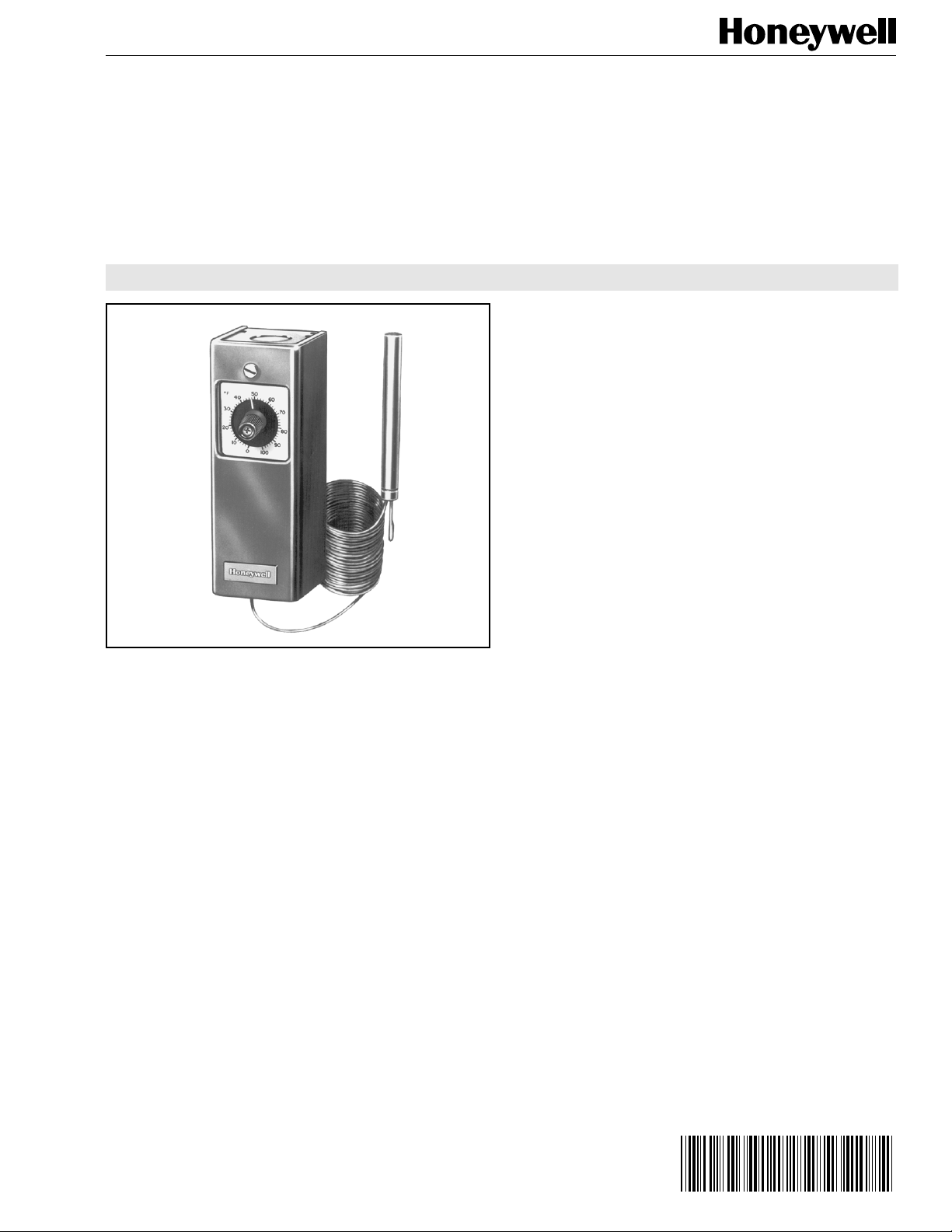
The T4031A,B,P and T6031A,B are temperature controllers
used in a variety of cooling applications where remote mounting
of the sensing element in the controlled medium is required.
• Reliable snap-acting spst or spdt switch.
• Ambient temperature compensated.
• Insert supplied with TRADELINE® models replaces
setpoint knob to discourage tampering.
Contents
General.................................................................................. 1
Features ................................................................................ 1
Specifications......................................................................... 2
Ordering Information .............................................................. 2
Installation ............................................................................. 3
Operation and Checkout ........................................................ 5
Copyright © 1995 Honeywell Inc. • All Rights Reserved
Page 2
T4031A,B,P; T6031A,B REFRIGERATION TEMPERATURE CONTROLLERS
SPECIFICATIONS
IMPORTANT
TRADELINE® Models
TRADELINE® Model Available:
Capillary Lengths and Temperature Ranges:
T4031A,B 5 1.5 -30 to 50 -34 to 10 Fixed at 3.5 Fixed at 1.6
T6031A,B 5 1.5 -15 to +90 -9 to +32 Fixed at 3.5 or Adjust. from 3.5 to 12 Fixed at 1.6 or Adjust. from 1.6 to 7
a
The specifications given in this publication do not
include normal manufacturing tolerances. Therefore,
this unit may not exactly match the specifications
listed. Also, this product is tested and calibrated under
closely controlled conditions, and some minor
differences in performance can be expected if those
conditions are changed.
TRADELINE® models are selected and packaged to
provide ease of stocking, ease of handling, and maximum
replacement value. TRADELINE® model specifications are
the same as those of standard models except as noted
below.
T6031A Refrigeration Temperature Controller-spdt switch,
adjustable temperature differential, tamper-resistant insert.
Copper
Capillary
Tube Length Setting Range
Model ft m °F °C °F °C
20 6.1
T4031P 8 2.4 -30 to +90 -34 to +32 3.5 to 16 1.6 to 9
20 6.1
5 1.5 -30 to +50 -34 to +10
20 6.1
8 2.4 -30 to +90 -34 to +32
Dial scale markings in degrees Fahrenheit
a
Capillary Length:
8 ft (2.4m)
Additional Features:
TRADELINE® pack with cross reference label and special
instructions
Standard Models
T4031A Refrigeration Temperature Controller-spst switch
makes on temperature rise; fixed differential
T4031B Refrigeration Temperature Controller—same as
T4031A but less case
T4031P Refrigeration Temperature Controller—same as
T4031A but uses screw, not knob, to adjust setpoint
T6031A Refrigeration Temperature Controller-spdt switch,
fixed or adjustable temperature differential
T6031B Refrigeration Temperature Controller—same as
T6031A but less case
Switch Action:
T4031A,B,P spst switch makes R to W on temperature rise
T6031A,B spdt switch makes R to W on temperature rise,
R to B on temperature fall
Differential
ORDERING INFORMATION
When purchasing replacement and modernization products from your TRADELINE® wholesaler or your distributor, refer to the
TRADELINE® catalog or price sheets for complete ordering number, or specify:
1. Order number. 4. Length of copper capillary tube.
2. Setting range. 5. Accessories, if desired.
3. Fixed or adjustable differential (T6031).
If you have additional questions, need further information, or would like to comment on our products or services, please write or
phone:
1. Your local Honeywell Home and Building Control Sales office (check white pages of your phone directory).
2. Home and Building Control Customer Relations
Honeywell, 1885 Douglas Drive North
Minneapolis, Minnesota 55422-4386
In Canada—Honeywell Limited/Honeywell Limitée, 35 Dynamic Drive, Scarborough, Ontario M1V 4Z9. International
Sales and Service Offices in all principal cities of the world.
60-2177—3
2
Page 3
T4031A,B,P; T6031A,B REFRIGERATION TEMPERATURE CONTROLLERS
Electrical Ratings:
Normally
Closed
Full Load
8165.1 8
Amp
Locked Rotor
48 80 30.6 40
Amp
a
Makes on temperature rise.
Pilot Duty:
125 VA
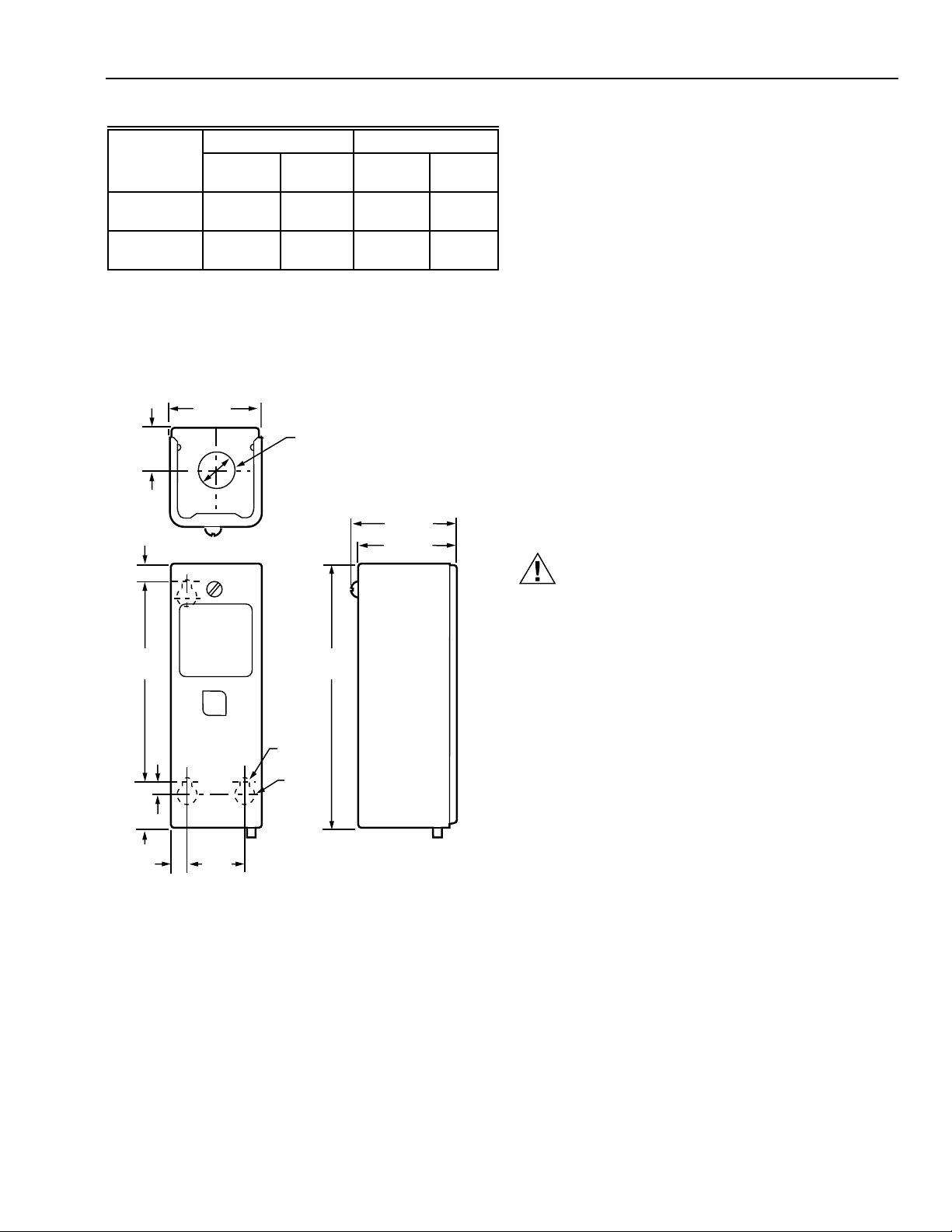
Dimensions:
See Fig. 1
2 (51)
15/16
(24)
17/32
(13)
120 Vac 240 Vac
Normally
Open
KNOCKOUT FOR 1/2 IN. (13 MM)
CONDUIT (2)
a
Normally
Closed
2-1/4 (57)
2-1/8 (54)
Normally
Open
7617ABZ Bag Assembly—for mounting controller to fan coil
units
801534 Calibration Wrench
a
7640HY Standoff Bracket Bag Assembly—to mount
controller to an insulated duct
130883 Universal Mounting Bracket
194899 Tamper-resisting Insert Button
Celsius Scaleplates:
194486 D: -15°C to +35°C replaces (0°F to 100°F)
scaleplate
194486H: 15°C to 75°C replaces (55°F to 175°F)
194486F: 75°C to 125°C replaces (160°F to 260°F)
INSTALLATION
When Installing this Product…
1. Read these instructions carefully. Failure to follow them
could damage the product or cause a hazardous
condition.
2. Check the ratings given in the instructions and on the
product to make sure the product is suitable for your
application.
3. Installer must be a trained, experienced service technician.
4. After installation is complete, check out product operation
as provided in these instructions.
4-3/16
(107)
29/32
(23)
3/8
(9)
7/32
(6)
1-3/16
(30)
7/32 (6)
DIA. (3)
3/8 (10)
DIA. (3)
5-5/8
(136)
Fig. 1. Dimensions of T4031, T6031 in in. (mm).
Underwriters Laboratories Inc.:
Listed
Maximum Ambient Operating Temperature:
125°F (52°C)
CAUTION
• Disconnect power supply before installation to prevent
electrical shock and equipment damage.
• Do not damage or change shape of capsule. Deformed capsule will cause calibration offset.
Mounting
Install controller in any convenient location. Make sure that the
sensing bulb reaches the system to be controlled. The ambient
temperature must not exceed 125°F (52°C) in the area where
the controller is installed.
Install the sensing element where it can sense the average
temperature. Avoid sharp bends or kinks in the capillary tubing
that can affect the accuracy of the controller. Carefully coil the
excess capillary tubing and leave it directly beneath the
controller.
M4496
The 130883 Mounting Plate furnished with TRADELINE®
models allows the control to be mounted in existing mounting
holes.
Duct Installation
Position the sensing bulb in the duct to sense the average air
temperature. Avoid mounting the bulb close to hot pipes,
cooling coils, etc.
Accessories:
112622AA Immersion Well—short-necked, 1/2 in. NPT,
copper
7617ABY Compression Fitting—50 psi water, 15 psi air
107324A Bulb Holder—for duct installation
105900 T-strap—for strapping bulb to pipe
The 107324A Bulb Holder is available for suspending the bulb
in a duct. See Fig. 2.
3
60-2177—3
Page 4

T4031A,B,P; T6031A,B REFRIGERATION TEMPERATURE CONTROLLERS
COMPOSITION
PACKING
M8970
Fig. 2. 107324A bulb holder.
To install duct:
1. Make a hole in duct wall to admit sensing bulb into
holder.
2. Using holder as template, mark and drill mounting holes.
3. Break off bulb holder to required length. (Be sure holder
is long enough to hold sensing bulb away from duct wall
and in freely circulating air.)
4. Place capillary tubing in bulb holder channel, with bulb at
inner end of holder. Pinch together top edges of channel
segments.
5. Insert assembled bulb and holder into duct, and fasten to
duct wall with screws supplied.
(SLIT)
PACKING NUT
Fig. 3. Compression fitting installation.
THREAD
SLOTTED WASHERS
ASSEMBLED
IN PAIRS:
BULB RETAINING
CLAMP
SENSING
BULB
BOILER PLUG
M4492
IMMERSION WELL
Tank Installation
The sensing bulb can be inserted directly into a tank using a
compression fitting; or the bulb can be inserted into an immersion well (order separately), which is screwed into a tank or
boiler.
Select a location where liquid of average temperature can
circulate freely around the sensing bulb.
Using Compression Fitting (Fig. 3)
1. Drain system. Screw boiler plug into properly sized and
threaded boiler or pipe tapping.
2. Place packing nut on capillary tubing.
3. Slide sensing bulb completely through boiler plug.
4. Place composition disc and the four slotted brass
washers on capillary tubing.
5. Slide assembly into boiler plug and tighten packing nut.
6. Refill system and check for leaks. Neatly coil excess
capillary tubing.
Using Immersion Well (Fig. 4)
1. Drain system. Screw the well into threaded fitting.
2. Refill system and check for leaks.
3. Insert sensing bulb into well until it bottoms.
4. Fit bulb retaining clamp over immersion well flange and
capillary tubing, and tighten screw.
CAPILLARY
WELL SPUD
M4493
Fig. 4. Immersion well installation.
Cold Room Installation
Locate the bulb in freely circulating air in the controlled area or
on the suction side of a refrigerant line, and secure the bulb in
position.
Wiring (Fig. 5)
All wiring must comply with local electrical codes and ordinances.
Two knockouts are provided, one at the top and one at the
bottom of the case for 1/2 in. conduit. Follow the wiring
instructions furnished with the heating or cooling system. For
replacement, make sure the new control is wired into the
system to operate the same as the old control.
TEMPERATURE FALL
2
B-R MAKES
TEMPERATURE RISE
R-W MAKES
60-2177—3
1
B
R
B TERMINAL ON T6031 CONTROLLERS ONLY.
1
AT SETPOINT MINUS DIFFERENTIAL SETTING.
2
W
M4494
Fig. 5. Wiring terminals on T4031 and T6031 temperature
controllers.
4
Page 5

T4031A,B,P; T6031A,B REFRIGERATION TEMPERATURE CONTROLLERS
OPERATION AND CHECKOUT
When the temperature at the sensing bulb rises above the
controller setpoint, a circuit is made between the R-W terminals. During a temperature fall, the R-W circuit breaks at the
setpoint temperature
minus
the switch differential. Controllers
with a B terminal break the B-R terminal circuit on a temperature rise to the setpoint. B-R makes again when R-W breaks on
a temperature drop. See Fig. 6.
For example, if a controller with a 3°F (1.7°C) differential is set
at 39°F (3.9°C), R-W makes when the bulb temperature rises to
39°F. Then during a temperature fall, R-W breaks when the
temperature drops to 35°F (1.7°C) (39°F minus the 3°F
differential [3.9°C minus the 1.7°C differential]).
On models with a B terminal, B-R makes when R-W breaks.
Then the temperature has to climb past the control differential
to the set point of 39°F (3.9°C) before the B-R circuit breaks
and the R-W circuit makes.
B R-WR-WB
CONTROL
39°F (4°C)
B-R MAKES
R-W BREAKS
B-R W B-R W
SWITCH ACTION ON
TEMPERATURTE RISE
SETPOINT
3.5°F (1.6°C)
DIFFERENTIAL
SWITCH ACTION ON
TEMPERATURE FALL
39°F (4°C)
35.5°F (2°C)
B-R MAKES
R-W BREAKS
M4495
Fig. 6. Operation of switch on temperature rise and fall.
SETTING
Set the controller to the system manufacturer’s recommended
settings, if available.
Temperature Setpoint Knob—Turn the knob on the front of the
case until the pointer indicates the temperature to be maintained in the controlled medium.
Screw—Insert a flatheaded screwdriver into the slot on the
shaft, which is located in the center of the scaleplate. Turn the
screwdriver clockwise to increase the temperature
control point. Turn the screwdriver counterclockwise to
decrease the temperature control point.
Adjustable Differential—With the cover off, turn the differential
adjustment wheel (marked 3-6-9-12°F) until the desired
differential is aligned with the notch in the frame. See Fig. 7.
Calibration
All controllers are carefully tested and calibrated at the factory
under controlled conditions. If the controller is not operating at a
temperature corresponding to the scale and differential setting,
verify that the bulb senses the average temperature of the
medium. If the temperature of the controlled medium is
changing rapidly, the differential will appear wider than its
setting.
TERMINAL SCREWS (3)
T6031 DIFFERENTIAL
ADJUSTMENT
Fig. 7. Internal view showing differential adjustment wheel
(applicable models).
For calibration, take an accurate temperature reading of the
controlled medium. Place an accurate thermometer near the
bulb of the controller, or refer to a thermometer installed as part
of the system. If the bulb of the controller is installed in an
inaccessible area, or if the controlled medium is unstable,
remove the bulb and place in a controlled bath for accurate
calibration.
These controllers are calibrated so the dial setting is the point
at which the R-W switch contacts make (B-R contacts break)
on a temperature rise. Measure the temperature at the bulb.
Rotate the dial counterclockwise from the top of the
scale, simulating a temperature rise, until the R-W switch
contacts make. Note the dial reading. If it differs from the
setpoint, calibrate the dial as follows:
1. Determine the number of degrees difference between the
set point and the point at which the contacts make.
2. Remove the dial knob and slip the fingers of the calibration wrench into the slots of the dial. Rotate the dial until
the fingers of the wrench drop into the slots of the
calibration nut under the dial. Note the dial indication at
this point. Turn the dial and the calibration nut up or down
scale the number of degrees that the set point differs
from the point at which the contacts make (determined in
step 1). For example, move the dial from 45 to 65
degrees for a 20 degree change in calibration.
3. Check the calibration adjustment by moving the dial up
and down the scale while watching the contacts make
and break. If dial is still out of calibration, repeat calibration procedure.
4. To install tamper-resisting insert on TRADELINE®
model, remove screw from adjustment knob, remove
knob, and install insert.
M4497
Fixed differential models are 3.5°F at midscale.
5
60-2177—3
Page 6

T4031A,B,P; T6031A,B REFRIGERATION TEMPERATURE CONTROLLERS
60-2177—3
6
Page 7

T4031A,B,P; T6031A,B REFRIGERATION TEMPERATURE CONTROLLERS
7
60-2177—3
Page 8

T4031A,B,P; T6031A,B REFRIGERATION TEMPERATURE CONTROLLERS
By using this Honeywell literature, you agree that Honeywell will have no liability for any damages arising out of your use or modification to, the
literature. You will defend and indemnify Honeywell, its affiliates and subsidiaries, from and against any liability, cost, or damages, including
attorneys’ fees, arising out of, or resulting from, any modification to the literature by you.
Home and Building Control
Honeywell Inc.
1985 Douglas Drive North
Golden Valley, MN 55422
60-2177—3 J.H. Rev. 5-95 Printed in U.S.A.
60-2177—3
Home and Building Control
Honeywell Limited-Honeywell Limitée
740 Ellesmere Road
Scarborough, Ontario
M1P 2V9
8
Helping You Control Your World
QUALITY IS KEY
www.honeywell.com/building/components
 Loading...