

Page 1
T6031E-H,J,K Thermostats
PRODUCT DATA
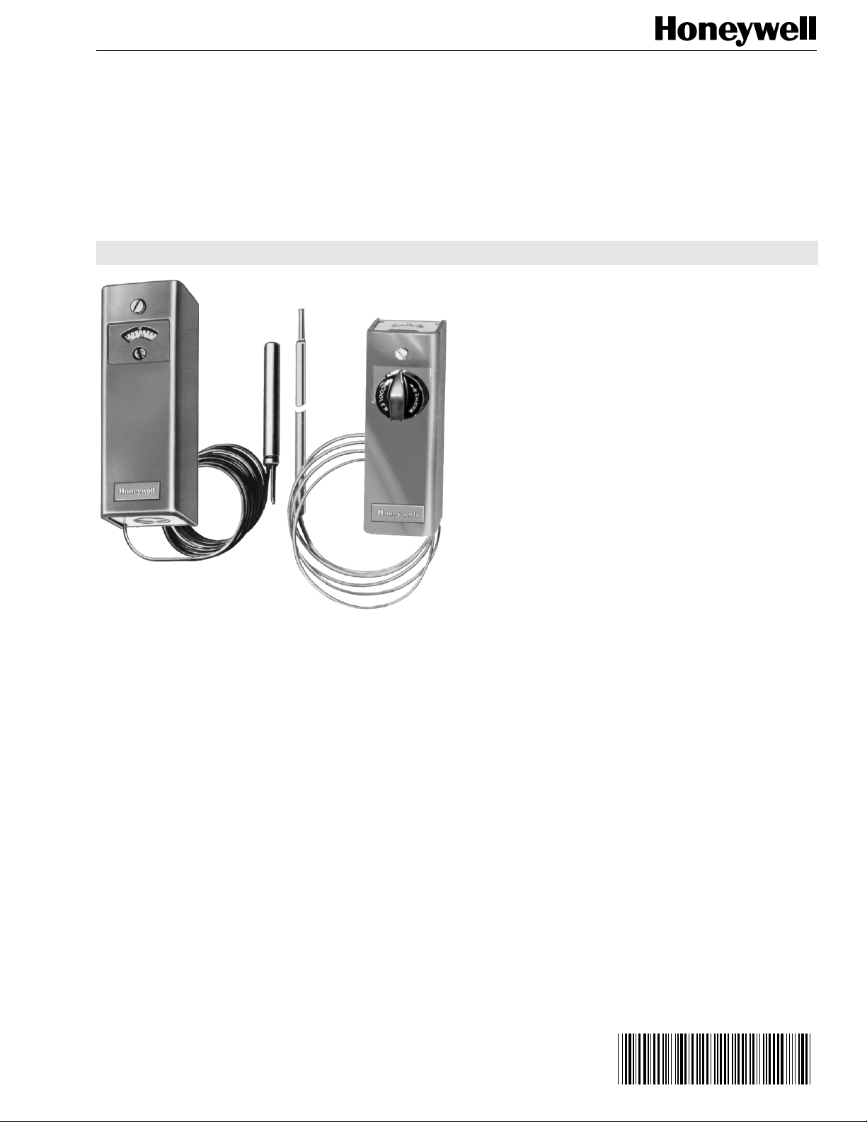
T6031 Thermostats control heating or cooling systems, or act
as changeover thermostats.
• T6031E,F models are unit thermostats.
• T6031G,H,J, are changeover thermostats.
• T6031K models are refrigeration thermostats for use in
freezers, chillers, and display cases.
• Models with case mount through holes in the back of
the case.
• Models without case mount with front or back mounting
brackets.
• Enclosed switches resist the effects of dust and
moisture.
• Setpoint adjusts with knob or screw on front of thermostat.
T6031G.H,J,K T6031E,F
Copyright © 1995 Honeywell Inc. • All Rights Reserved
63-2118-3
Page 2
T6031E-H,J,K THERMOSTATS
SPECIFICATIONS
Models:
T6031E,F,G,H,J,K. See Table 1 and description that follows.
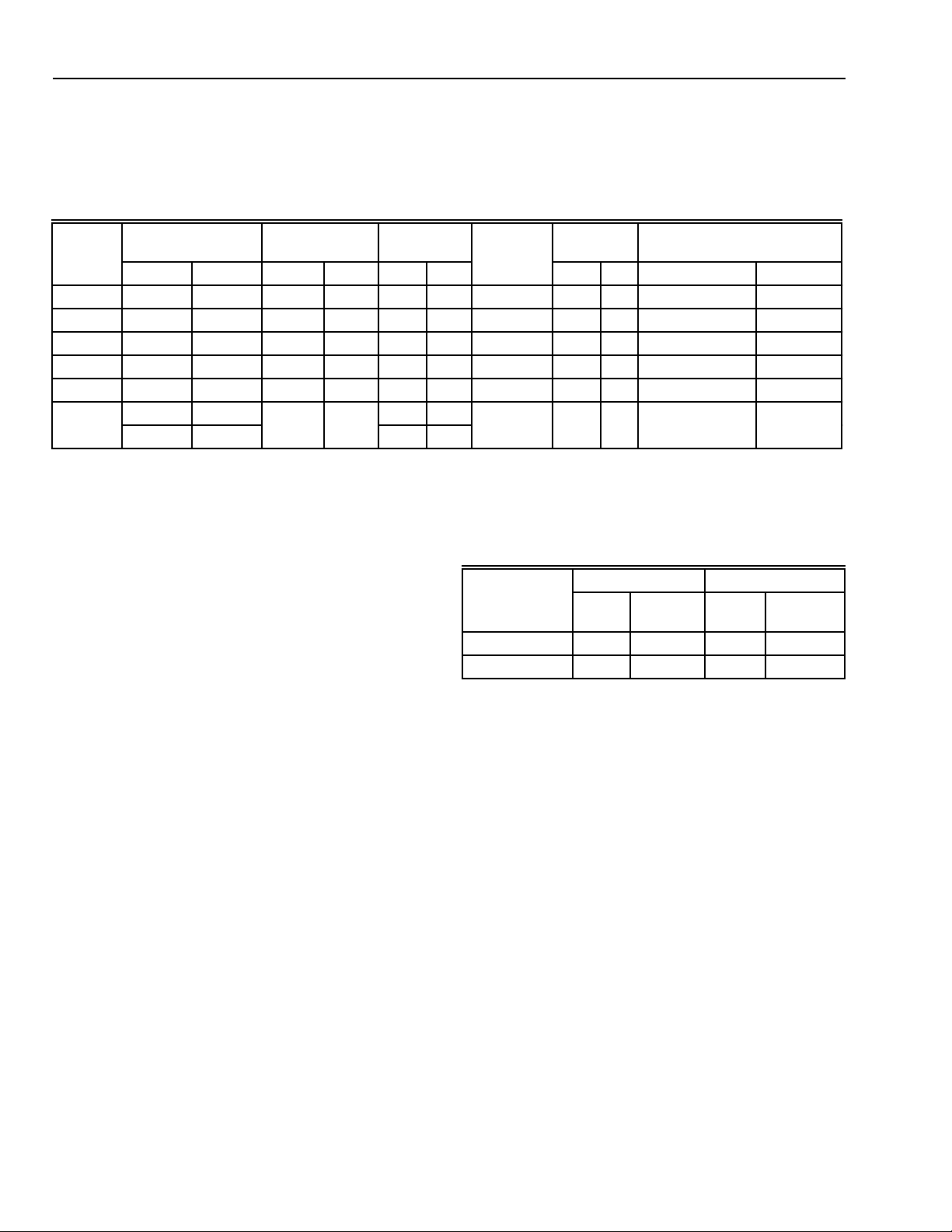
Table 1. Model numbers and description.
Model
Number
T6031E 55 to 90a13 to 3 2 150 66 1-1/2 1 enclosed 5-1/2 1.7 5/16 x 11-11/16 8 X 297
T6031F 55 to 90a13 to32 150 66 1-1/2 1 front 5-1/2 1.7 5/16 x 11-11/16 8 X 297
T6031G 0 to 90 -18 to32 155 68 2 — back 6-1/4 1.9 3/8 x 3 10 X 76
T6031 H 0 to 95 -18 to 35 150 66 3 2 back 2 0.6 3/8 x 3-1 /2 10 X 89
T6031J 55 to 85 13 to 29 205 96 5 3 enclosed 5-1/2 1.7 3/8 x 3 10 x 76
T6031K 15 to 75 -9 to 24 155 68 5 3 enclosed 5-1/2 1.7 3/8 x 3 10 x 76
a
Knob marked warmer-cooler.
Control Range
°F °C °F °C °F °C
-20 to 50 -29 to 10 2 1
Max. Element
Temperature Differential
Type of
Mounting
Capillary
Length Bulb Size
f t m in. mm
Models (also refer to Table 1):
T6031E Unit Thermostat: 1 light duty spdt switch; with base
and cover.
T6031F,G Unit Thermostat: 1 light duty spdt switch; without
case.
T6031G,H Changeover Thermostat: 1 standard spdt switch;
without case.
T6031J Changeover Thermostat: 1 standard spdt switch;
with case and cover.
T6031K Refrigeration Thermostat: 1 standard spdt switch;
with case and cover.
Terminals:
8/32 binder-head screws and cup-washers.
Electrical Ratings (A):
Switches—
Refer to
Model Used
Light Duty 3.2 19.2 1.6 9.6
Standard 8.0 48.0 5.1 30.6
T6031H,J,K: 0.25A at 1 /4V to 12 Vdc inductive load.
120 Vac 240 Vac
Full
Load
Locked
Rotor
Full
Load
Locked
Rotor
ORDERING INFORMATION
When purchasing replacement and modernization products from your TRADELINE® wholesaler or your distributor, refer to the price
sheets for complete ordering number, or specify—
1. Model number 4. Optional specifications, if desired.
2. Scale range. 5. Accessories, if desired.
3. Mounting bracket on models without case.
If you have additional questions, need further information, or would like to comment on our products or services, please write or
phone:
1. Your local Honeywell Residential Sales Office (check white pages of your phone directory).
2. Home and Building Control Customer Satisfaction
Honeywell Inc., 1885 Douglas Drive North
Minneapolis, Minnesota 55422-4386 (612) 951-1000
(In Canada—Honeywell Limited/Honeywell Limitee, 740 Ellesmere Road, Scarborough, Ontario M1P2V9)
International sales and service offices in all principal cities of the world.
63-2118—3
2
Page 3
M7525
BRACKET DEPTH–1-11/16 (43)
OVERALL LENGTH–3-11/16 (94)
OVERALL DEPTH
(LESS SHAFT)–2-1/8 (54)
CLEARANCE BETWEEN
BRACKET AND BASE
OF DIAL–1/4 (6)
NO. 10-32 TAP (2)
2-1/4
(57)
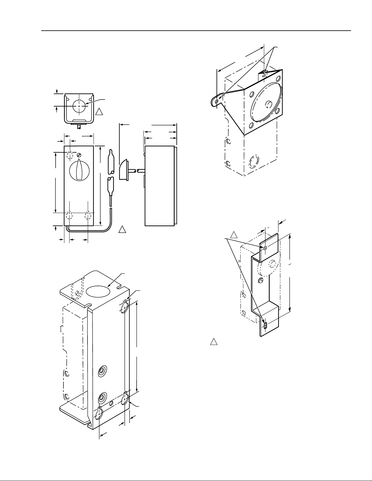
Mounting Means:
ON THE 114496 BRACKET, THE MOUNTING HOLES ARE TWO
NO. 8-32 TAPPED HOLES. THE 107940 BRACKET IS MOUNTED
WITH A 5/32 (4) DIAMETER HOLE AT THE TOP AND A VERTICAL
5/32 X 5/16 (4 X 8) SLOT AT THE BOTTOM.
1
1
M9090
3
16
4
(106)
3
4
(19)
MOUNTING
HOLES
OVERALL LENGTH: 5 (127)
OVERALL DEPTH LESS
ADJUSTING DIAL SHAFT:
2-1/8 (54)
T6031E,J,K: holes in back of case.
T6031F,G,H: front or back mounting.
Dimensions:
Case: see Fig.1 and 2.
Models without case, including brackets: see Fig. 3 and 4.
T6031E-H,J,K THERMOSTATS
15/16
(24)
4-3/16
(106)
15/16
(24)
3/8
(10)
2 (51)
1-7/32
(31)
3/8 (10)
KNOCKOUT FOR
1/2 CONDUIT (BOTH ENDS)
1
5-5/8
(143)
1
4-7/16 (113)
2-1/4 (57)
2-1/8 (54)
TOP KNOCKOUT IS 7/8 FOR
ALL BUT T6031H ENCLOSED.
M7523
Fig. 1. T6031 mounting dimensions in in. (mm).
7/8 (22) DIA. KNOCKOUT
(BOTH ENDS)
Fig. 3. Front mounting bracket in in. (mm).
Fig. 2. Case mounting holes in in. (mm).
1-7/32
(31)
3/16 (5) DIA.
4-3/16
(106)
3/8 (10) DIA.
5/16 (9)
M7524
Fig. 4. Back mounting bracket in in. (mm).
Finish:
Gray.
Underwriters Laboratories Inc. listed:
T6031F-H: File E4436, Vol. 4, Guide XAPX2;
T6031E,J: File E4436, Vol. 4, Guide XAPX;
T6031K: File SA481, Vol. 1, Guide SDFY.
Accessories:
105900 Mounting Clamp for mounting element to a pipe; for
T60031G,H,J Changeover Thermostats.
3
63-2118—3
Page 4
T6031E-H,J,K THERMOSTATS
Compression fittings:
Bulb Size Brass Mild Steel Stainless Steel
Up to 1/2 in.
(127 mm) dia.
Waste nuts: for 1/2 in. NPT opening;
7617BF for 3/4 in. NPT opening.
Immersion well assemblies:
Bulb Size
3/8 x 3 in.
(9 5 x 76.2 mm)
(1-1/2 in. [38.1]
insulation)
(3 in. [76.2 mm]
insulation)
For additional information on accessory parts, refer to the
TRADELINE® Catalog.
7617M 7617Y 7617BE
Copper Stainless Steel
1/2 in.
NPT
121371A 121371B 121371E 121371F
121371L 121371M — —
3/4 in.
NPT
1/2 in.
NPT
3/4 in.
NPT
INSTALLA TION
When Installing this Product…
1. Read these instructions carefully. Failure to follow them
could damage product or cause a hazardous condition.
2. Check ratings given in instructions and on product to
make sure product is suitable for your application.
3. Installer must be a trained, experienced service
technician.
4. After installation is complete, check out product operation
as provided in these instructions.
CA UTION
Disconnect power supply before beginning installation
to prevent electrical shock and equipment damage.
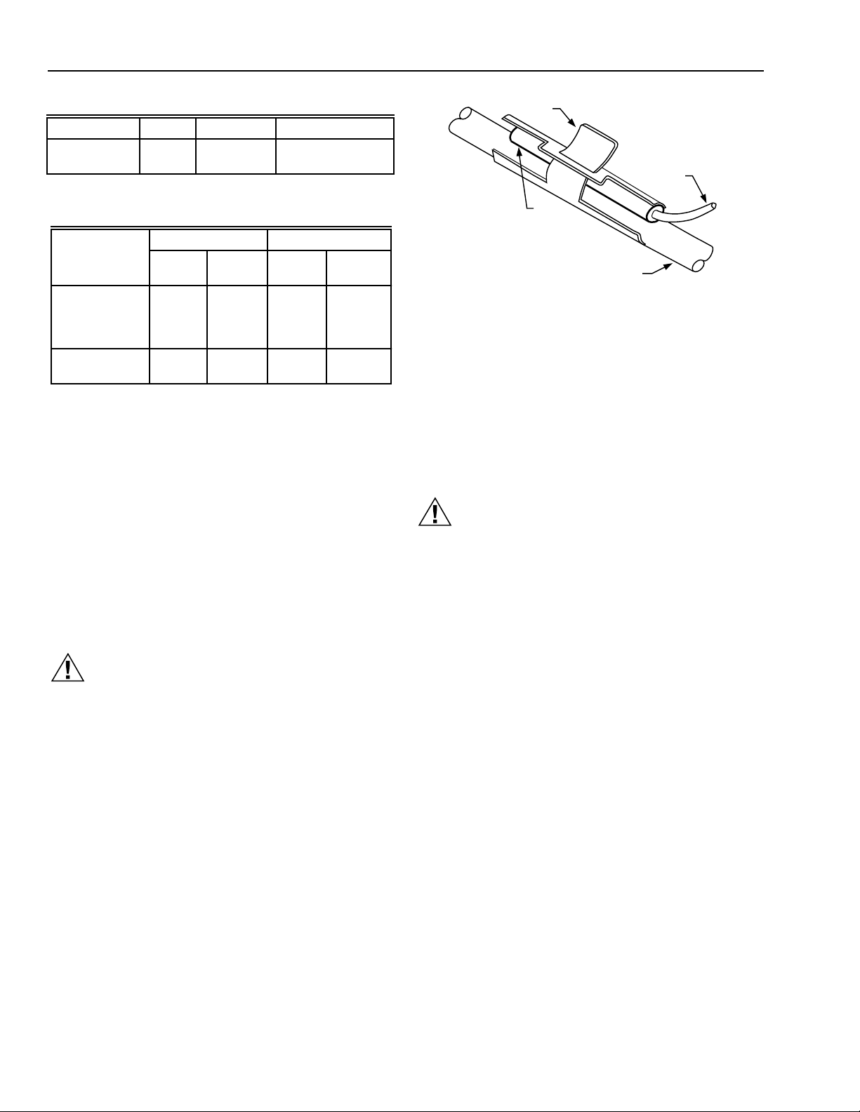
T-CLAMP
CAPILLARY
TUBING
BULB
SUPPLY WATER PIPE
Fig. 5. Bulb strapped to supply water pipe with 105900
T-clamp.
M8836
Mounting Sensing Elements
T6031E,G,H models—install bulb in return airflow.
T6031G,H,J models—install bulb in water supply where water
of average temperatures circulates around it The bulb may be
strapped to a water pipe using a 105900 Clamp (see Fig. 5) or
as follows:
1. Secure controller bulb to pipe with duct hanger wire or
metal hose clamps (Fig 6. top).
CA UTION
Do not over tighten clamps to point of distorting sensor
bulb. Over tightening clamps will cause a significant
shift in bulb calibration
(Steps 2 and 3 are optional and are to be used when large
fluctuations in the ambient temperature occur near the pipe)
2. Cover bulb and pipe with foam rubber insulation extending at least 6 in. (152 mm) beyond both ends of bulb (Fig.
6, bottom).
3. Secure foam rubber with duct tape. DO NOT ALLOW
DUCT TAPE TO CONTACT PIPE.
Location and Mounting
T6031 Thermostats mount either vertically or horizontally on a
wall or panel. The remote bulb can be located as far from
controller as capillary tubing allows. The bulb should be located
where it senses the average temperature of the medium to be
controlled.
63-2118—3
4
Page 5

T6031E-H,J,K THERMOSTATS
SET POINT
FOR T6031H
SET POINT
SWITCH
DIFFERENTIAL
TEMPERATURE
RISE
R AND W LOCATIONS
DEPEND ON MODEL
AND CONSTRUCTION
W
B
R
BREAKS R-B;
MAKES R-W
ON RISE
MAKES R-B;
BREAKS R-W
ON FALL
M9089
L1
(HOT)
L2
1
1
POWER SUPPLY. PROVIDE DISCONNECT MEANS AND OVERLOAD
PROTECTION AS REQUIRED.
W
W
W
B
B
B
R
R
R
W
B
R
T
T
T6031E,F UNIT
THERMOSTAT
T678C CHANGEOVER
THERMOSTAT-ELEMENT
ON SUPPLY WATER PIPE
V2045/V5045
RADIATOR
VALVE
M7538
BULB STRAPPED TO PIPE
CAUTION
DO NOT OVERTIGHTEN CLAMPS TO AVOID SENSOR
BULB DISTORTION. OVERTIGHTENING CLAMPS
MAY CAUSE A SIGNIFICANT SHIFT IN CALIBRATION.
APPROX. 3 FT
(0.9 M)
CAPILLARY
TUBE
DUCT HANGER WIRE OR
METAL HOSE CLAMPS
FOAM TAPED OVER STRAPPED BULB (OPTIONAL)
CAPILLARY
TUBE
DUCT TAPE
FOAM RUBBER WRAP
(EXTENDS 6 in. (152 mm)
BEYOND ENDS OF SENSOR)
WIRING
Disconnect power supply before connecting wiring to prevent
electrical shock and equipment damage. All wiring must comply
with local codes and ordinances.
When wiring, refer to wiring diagrams furnished with system
equipment and to Fig. 7 through 11.
T6140 BULB
PIPE
PIPE
M8835
Fig. 6. Strap-on mounting of T6031 bulb on a boiler
discharge pipe.
Mounting Controller
Models With Case
1. Loosen the captive mounting screw above the dial on the
face of the thermostat and remove cover (On models
with adjustment knob, remove knob first by loosening the
setscrew.)
2. Fasten case to wall or panel through mounting holes in the
back of case with furnished screws. (See Fig.1 and 2.)
3. Run tubing through the most convenient of the four
corner notches in case. Do not bend tubing so sharply
that flow is restricted. Leave excess tubing coiled near
the thermostat.
4. Make wiring connections according to instructions in the
WIRING section.
5. Replace cover, careful not to not pinch tubing. Tighten
cover mounting screw.
Models Without Case
Front or back mounting brackets are available. See Fig. 3 and 4
for mounting information and dimensions.
Fig. 7. T6031 switch terminal arrangement and switching.
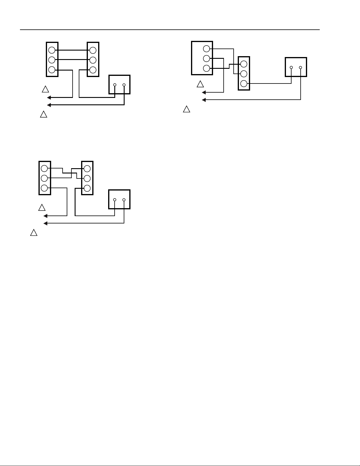
Fig. 8. Typical hookup for T6031E,F with T678C
changeover thermostat controlling V2045/V5045 Valve on
5
both heating and cooling cycles.
63-2118—3
Page 6
T6031E-H,J,K THERMOSTATS
T6031F UNIT
THERMOSTAT
W
B
R
1
L1
(HOT)
L2
POWER SUPPLY. PROVIDE DISCONNECT MEANS AND
1
OVERLOAD PROTECTION AS REQUIRED.
T6031G,H CHANGEOVER
THERMOSTAT
W
B
MOTORIZED OR SOLENOID
VALVE IN WATER SUPPLY
R
TO UNIT CONTROLLER
M7539
Fig. 9. Typical hookup for T6031F with T6031G,H
changeover thermostat controlling N.O. Valve on both
heating and cooling cycles.
T6031F UNIT
THERMOSTAT
W
B
R
1
L1
(HOT)
L2
POWER SUPPLY. PROVIDE DISCONNECT MEANS AND
1
OVERLOAD PROTECTION AS REQUIRED.
T6031G,H
CHANGEOVER
W
THERMOSTAT
B
MOTORIZED OR SOLENOID
VALVE IN WATER SUPPLY
TO UNIT CONDITIONER
R
M7540
Fig. 10. Typical hookup for T6031F unit thermostat with
T6031G,H changeover thermostat controlling motorized or
solenoid valve on both heating and cooling cycles.
T6051 HEAVY–DUTY
1
THERMOSTAT
T6031J
CHANGEOVER
W
THERMOSTAT
B
R
SOLENOID
OR FAN
M7541
N.O.
COM
N.C.
L1
(HOT)
L2
POWER SUPPLY. PROVIDE DISCONNECT MEANS AND
1
OVERLOAD PROTECTION AS REQUIRED.
Fig. 11. Typical hookup for T6031J changeover thermostat
used with T6051 line voltage thermostat to control N.O.
valve or fan on both heating and cooling cycles.
OPERA TION AND CHECKOUT
After the T6031 is installed and wired into the system, check
controller action by raising the temperature set point about 10°F
(5.6°C) above room temperature. Heating equipment should
stop or cooling equipment should begin operation, depending
on the application. Lower setpoint below room temperature.
Heating equipment should begin operation or cooling equipment should stop, depending on application.
For questions about installation, operation, or checkout of this
equipment, contact your distributor or local Honeywell representative.
63-2118—3
6
Page 7

T6031E-H,J,K THERMOSTATS
7
63-2118—3
Page 8

T6031E-H,J,K THERMOSTATS
Home and Building Control
Honeywell Inc.
1985 Douglas Drive North
Golden Valley, MN 55422
Home and Building Control
Honeywell Limited-Honeywell Limitée
740 Ellesmere Road
Scarborough, Ontario
M1P 2V9
63-2118—3 J.H. Rev. 4-95 Printed in U.S.A. www.honeywell.com
63-2118—3
8
 Loading...