

Page 1
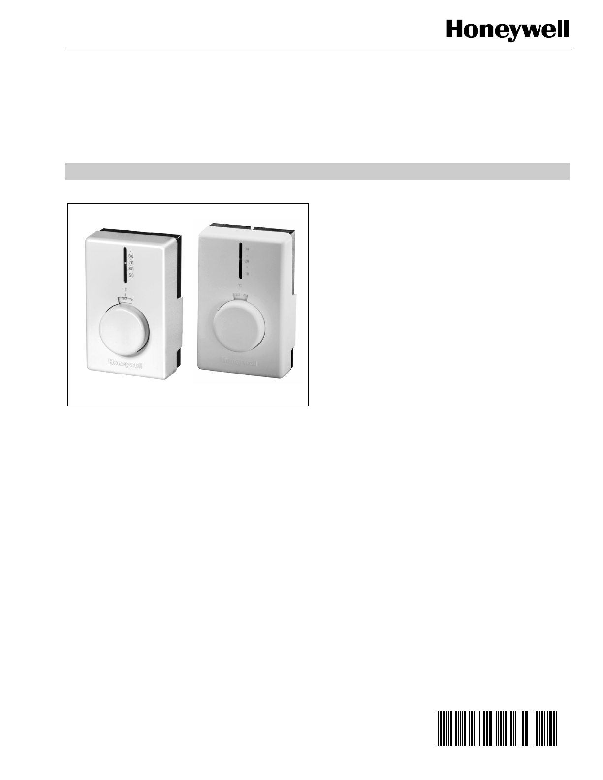
Electric Heating Thermostat
APPLICATION
The T4398 Electric Heating Thermostat provides precise,
accurate line voltage control of electric heating equipment. A
snap action switch makes the heating circuit on temperature
fall. B models feature double-line break in the Off position.
T4398A,B Precision
PRODUCT DATA
FEATURES
• Controls both fan-forced and baseboard electric
heaters.
• Vapor-filled dual diaphragm sensing element provides
high-temperature sensitivity with minimum droop.
• Canadian Standards Association (CSA) Performance
Certified up to 20A.
• CSA Certified, UL Listed up to 5 kW at 277 Vac.
• Long-life, industrial-grade Micro Switch™ mechanism.
• Rugged-engineered, plastic mounting base with
captive mounting screw.
• Color-coded flyleads compatible with aluminum wire
for quick installation.
• Replaces any standard wall-mounted electric heat
thermostat.
• Contemporary white styling.
• Operating temperature range of 50°F to 80°F (10° C to
30° C).
• Celsius and fahrenheit models available.
• Optional thermometer.
• Altitude compensation feature.
• Frost protection setting (A models only).
• Optional locking cover and range stops available.
® U.S. Registered Trademark
Copyright © 2002 Honeywell • All Rights Reserved
69- 1604
Page 2
T4398A,B PRECISION ELECTRIC HEATING THERMOSTAT
SPECIFICATIONS
Models:
T4398A: Makes heating circuit on temperature fall. With
setting knob at far left (counterclockwise) position, provides calibration-free frost protection setting of 40°F
(4°C). See Fig. 2.
T4398B: Makes heating circuit on temperature fall. With
setting knob at Off position, provides double line break
for fuse-protected 240V heating circuits. (See Fig. 3.)
Both models feature optional thermometer, located in the
cover, to indicate the actual room temperature.
Accessories (Not Included):
272804A Range Stop and Cover Locking Assembly:
Allows field-selection of minimum and maximum temperature settings. Includes range stop assembly, cover
locking-screws and wrench.
Setting Range:
Fahrenheit Models: Indicates range of 50°F to 80°F with
marking indications in 5°F increments.
Celsius Models: Indicates range of 10°C to 25°C with
marking indications in 1°C increments.
Differential:
Approximately 2°F (1°C) mechanical and thermal, non-adjust-
able.
Switch Type:
Enclosed industrial-grade Micro Switch˜™ snap switch.
T4398A: Single-line break (single-pole, single-throw).
T4398B: Double-pole, single-throw with double-line break
(double-pole, single-throw) in Off position.
Wiring Connections:
Six-inch (150 mm) stranded copper leadwires suitable for con-
necting to aluminum wiring if approved special service CO/
ALR connectors are used.
Electrical Rating:
22A non-inductive at 120/208/240 Vac.
19A non-inductive at 277 Vac.
Approval Ratings:
Underwriters Laboratories Inc: Listed; file no. E47434,
guide no. XAPX.
Canadian Standards Association: File no. LR1322.
Mounting:
Direct mounting on NEMA standard vertical 2 in. x 4 in. switch
box, or 4 in. x 4 in. box using 6-32 slot Robertson™
screws.
Sensing Element:
Vapor-filled, hermetically-sealed, stainless steel, dual dia-
phragm.
Thermometer (Optional):
Coil bimetal 50°F to 90°F (10°C to 30°C).
Barometric Sensitivity:
1°F/500 ft (0.3°C/kPa).
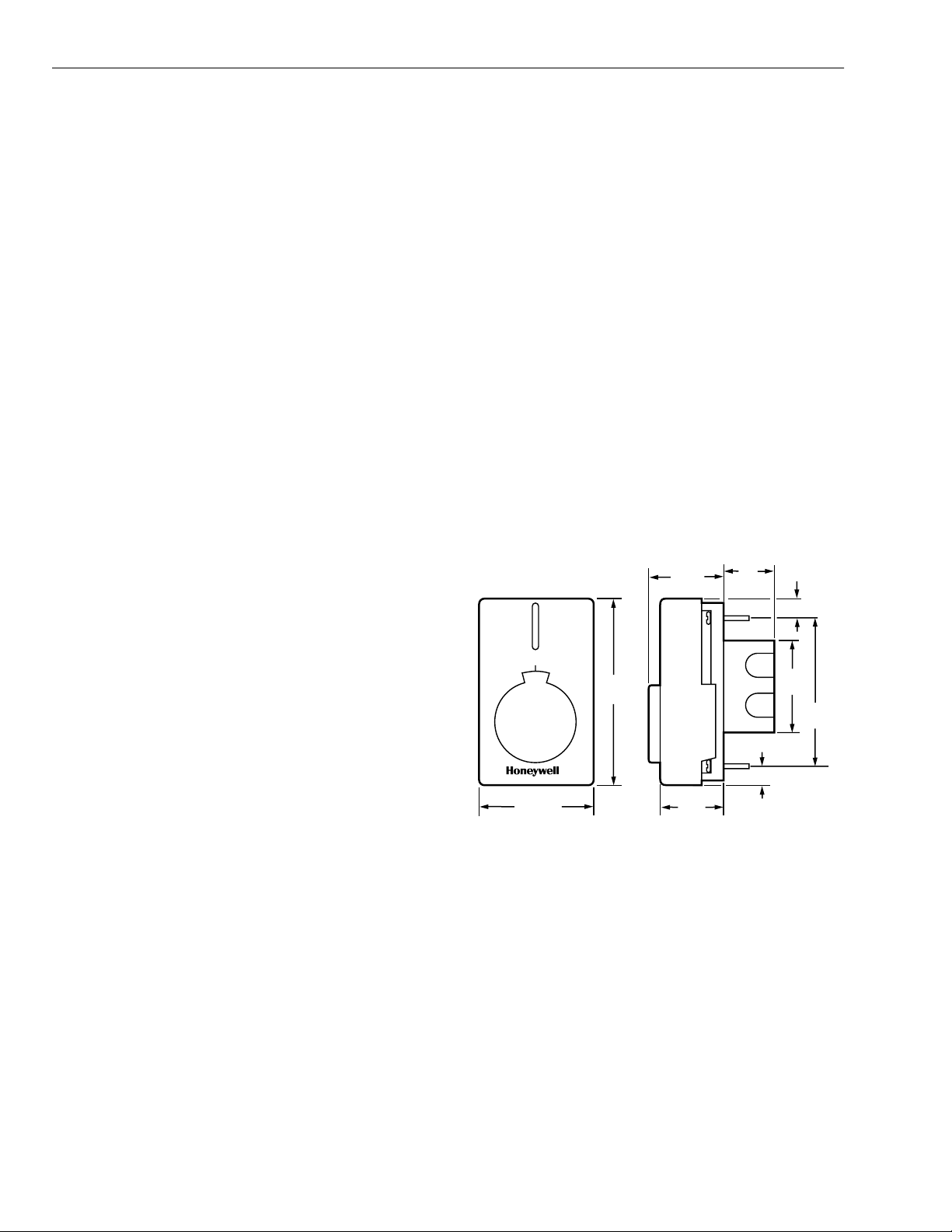
Dimensions:
See Fig. 1.
FRONT VIEW SIDE VIEW
1-3/4
(48)
80
•
70
•
60
•
50
•
˚F
4-3/8
(111)
3/4
(19)
1/2 (13)
2-1/8
(54)
3-1/4
(83)
Canadian Standards Association Performance Rating:
20A at 120/208/240 Vac.
69-1604 2
2-7/8 (73)
1-1/2
(39)
1/2 (13)
Fig. 1. T4398A,B dimensions in in. (mm).
M5795A
Page 3
INSTALLATION
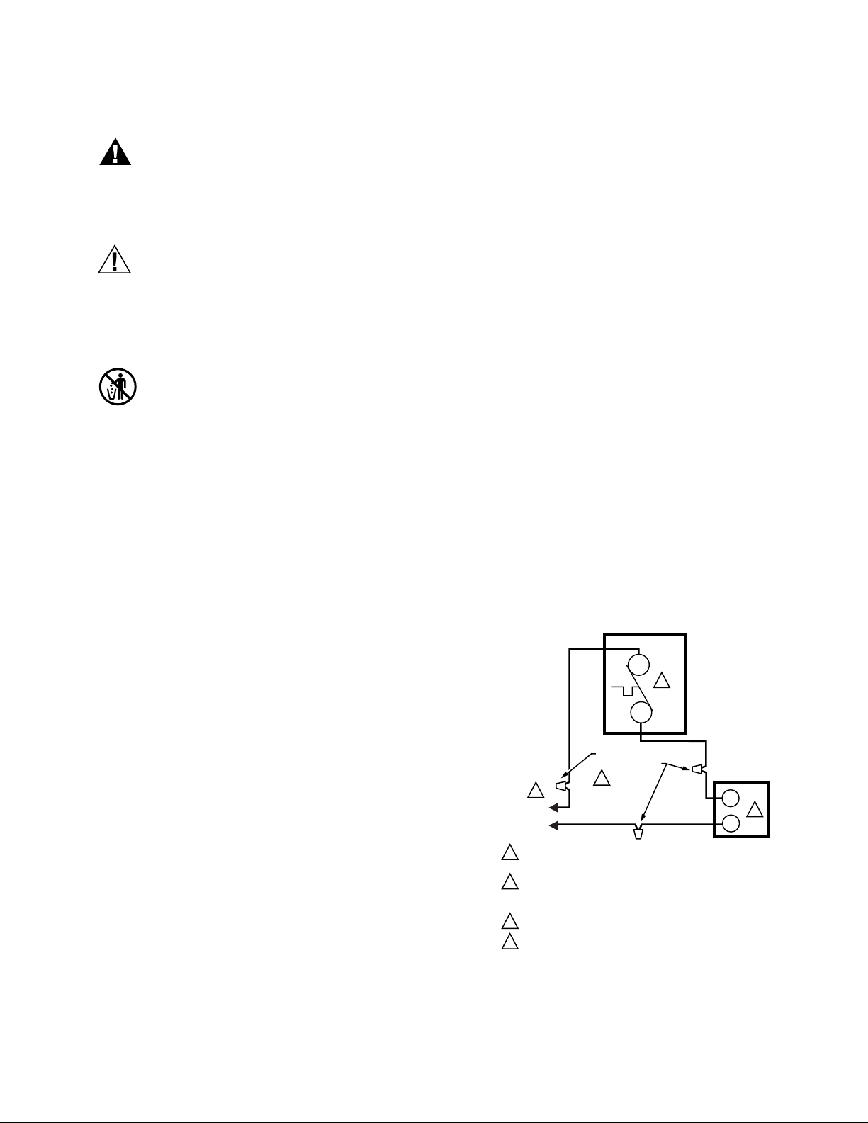
WARNING
120-277 Volt Line Voltage Hazard.
Can cause serious injury or death.
Do not install thermostat unless you are a trained,
experienced electrical service technician.
CAUTION
Electrical Shock Hazard.
Can cause personal injury and equipment
damage.
Disconnect power supply before connecting wiring.
Use a limit control when wiring the thermostat.
MERCURY NOTICE
If this control is replacing a control that contains
mercury in a sealed tube, do not place your old control
in the trash. Dispose of properly.
T4398A,B PRECISION ELECTRIC HEATING THERMOSTAT
NOTE: Make line voltage wiring connections directly to the
leadwires installed on the thermostat, using wire connectors approved for the number and size of conductors.
IMPORTANT
When using aluminum conductors, all wiring connections to the thermostat must be made to the factoryinstalled lead wire, using approved CO/ALR solderless connectors.
1. Connect all wires with the thermostat cover in place. Be
sure that all wire connectors are tight. Install any security features. See Fig. 2 and 3.
2. Pre-bend the solid conductors and push them into the
electrical box.
3. Remove the thermostat cover by grasping both the top
and bottom of the cover and pulling out..
IMPORTANT
Carefully handle the thermostat. Excessive pressure
can damage the control knob or sensing element.
Contact your local waste management authority for
instructions regarding recycling and the proper
disposal of an old control.
When Installing This Product . . .
1. Read these instructions carefully. Failure to follow them
could damage the product or cause a hazardous condition.
2. Check the rating given in the instructions and on the
product to make sure the product is suitable for your
application.
3. Installer must be a trained, experienced service technician.
4. After installation is complete, check out product operation as provided in these instructions.
5. Follow local codes for installation and application.
Selecting Location
— Mount the thermostat on an approved electrical junction
box.
— Locate the thermostat 4 to 5 ft (1.5m) above the floor on an
inside wall where the thermostat can be exposed to
average room temperature.
— Locate the thermostat away from concealed warm or cold
water pipes, light switches and dimmers, and refrigerators.
— Locate the thermostat away from drafts of hallways,
fireplaces, stairways, and fans.
Mounting
When replacing an old line voltage thermostat:
— Carefully remove the old thermostat to avoid damaging the
wiring insulation.
— Check the old insulation for cracks, chips, or fraying and
apply approved electrical tape, where necessary, to ensure
adequate insulation.
4. Turn the dial so the setpoint indicator is at the 12 o’clock
position. (This prevents accidental damage to the dialstop during mounting.)
5. Using the screwdriver, secure the thermostat to the
electrical box by tightening the two mounting screws.
See Fig. 4.
6. Level the thermostat only for appearance.
7. Tighten the screws and replace the cover.
T4398A
L1
4
T1
SOLDERLESS
CONNECTORS
1
L1
(HOT)
L2
POWER SUPPLY. PROVIDE DISCONNECT MEANS AND
1
OVERLOAD PROTECTION AS REQUIRED.
USE SPECIAL SERVICE CO/ALR SOLDERLESS CONNECTORS
2
WHEN CONNECTING ALUMINUM CONDUCTORS OR A FIRE
HAZARD MAY RESULT.
USE A SEPARATE LIMIT CONTROL IN THE HEATING APPLIANCE.
3
BREAKS AND REMAKES BELOW -31°F (-35°C); NORMALLY
4
THERMAL ACTIVATED. BREAKS ON TEMPERATURE RISE;
MAKES ON TEMPERATURE FALL.
2
ELECTRIC
HEATER
3
M5791B
Fig. 2. T4398A typical hookup.
3 69-1604
Page 4

T4398A,B PRECISION ELECTRIC HEATING THERMOSTAT
T4398B
L1
L2
3
T1
T2
L2
1
L1
(HOT)
POWER SUPPLY. PROVIDE DISCONNECT MEANS AND
1
OVERLOAD PROTECTION AS REQUIRED.
USE SPECIAL SERVICE CO/ALR SOLDERLESS CONNECTORS
2
WHEN CONNECTING ALUMINUM CONDUCTORS OR A FIRE
HAZARD MAY RESULT.
BREAKS AT POSITIVE OFF AND REMAKES UNDER –31°F (–35°C);
3
NORMALLY THERMALLY ACTIVATED. BREAKS ON TEMPERATURE
RISE; MAKES ON TEMPERATURE FALL.
USE A SEPARATE LIMIT CONTROL IN THE HEATING APPLIANCE.
4
BREAKS AT POSITIVE OFF ONLY; NOT THERMALLY ACTIVATED.
5
DO NOT CONNECT GROUNDED CONDUCTOR (NEUTRAL) ON
6
120 OR 227V CIRCUITS. INSULATE AND TAPE OR CUT OFF
RED WIRES IF UNUSED.
SOLDERLESS
CONNECTORS
2
RED
WIRE
6
5
ELECTRIC
HEATER
M5792B
WALL
THERMOSTAT
BASE
5
0
5
6
5
5
0
6
0
OUTLET
4
BOX
SETTING DIAL
INDICATOR
7
5
7
0
8
MOUNTING
SCREWS (2)
M5797
Fig. 4. Mounting thermostat to outlet box.
Fig. 3. T4398B typical hookup.
69-1604 4
Page 5

OPERATION AND CHECKOUT
After the thermostat is installed and wired, check out normal
operation as follows:
1. Turn setting dial fully clockwise until the switch clicks
and the electric heater starts to heat.
2. Turn the dial fully counterclockwise; the power circuit
breaks and the electric heater starts to cool.
3. The T4398 is a more accurate thermostat, allowing
users to be more comfortable at lower setpoint settings
(saving energy and lowering heating costs). To determine final setting:
a. Begin with setting the dial indicator at 68°F (20°C).
b. After two operating hours, if not comfortable, adjust
setpoint to raise or lower the temperature, adjusting
temperature only a few degrees each time.
Calibration
T4398A,B PRECISION ELECTRIC HEATING THERMOSTAT
KPa ELEVATION
101
(SEA LEVEL)
99
WINNIPEG
REGINA
95
EDMONTON
93
BAROMETRIC PRESSURE
89
CALGARY
1.2 2.0 2.8 3.6 4.4 5.2 6.0
0.4
ELEVATION IN METERS
240M
574M
677M
1079M
0
CITIES WITH
TEMPERATURE
CORRECTIONS
( C CORRECTIONS
TO BE ADDED)
(FOR EXAMPLE, A
CORRECTION OF
APPROXIMATELY 3.5 C
INCREASING
WOULD BE INDICATED
FOR INSTALLATION
IN CALGARY.)
M20354
IMPORTANT
Do not assume the thermostat is out of calibration
until it is installed and allowed to operate for several
hours.
The T4398 is accurately calibrated at the factory under
controlled conditions. The snap switch turns on heat when the
setpoint is raised to room temperature.
The vapor-filled diaphragm sensor is affected by barometric
pressure and altitude. Deviations up to 1°F (±1/2°C) are within
normal operation. The control point drops 2°F every 1000 ft
(1°C/300m) above sea level. See Fig. 5 and 6.
10
8
6
4
2
0
0 1000F2000
SEA
LEVEL
ATLANTA
LOS ANGELES
LAS VEGAS
3000 4000 5000 6000
ELEVATION IN FEET
DENVER
M20353
Fig. 6. T4398 altitude correction in (m).
To calibrate (see Fig. 7):
1. Remove cover and place it in a location that allows it to
sense the room temperature.
NOTE: Allow several minutes for the thermometer to stop
being affected by the heat from your hand.
2. Rotate the setpoint knob counterclockwise until you
hear the switch click.
3. Hold the setpoint knob firmly and rotate the setpoint
scale ring counterclockwise until 12 o’clock on the ring
is aligned with the thermometer cover.
4. The heat from your hand will affect the diaphragm sensor so wait five minutes and verify the calibration.
Fig. 5. T4398 altitude correction in (ft).
5 69-1604
Page 6

T4398A,B PRECISION ELECTRIC HEATING THERMOSTAT
THERMOSTAT
BASE
6
5
0
7
6
5
7
0
8
0
5
5
5
0
SETTING KNOB
AT 12 O'CLOCK
POSITION
SCALE RING
SETTING KNOB
Fig. 7. Calibrating the thermostat.
M5796
THERMOSTAT
COVER
LOCKING
COVER SCREW
THERMOSTAT BASE
LOCKING
COVER
CLIP
ALLEN WRENCH
M5798
Security Features
To install the locking cover (select models (Fig. 8):
1. Remove cover by swinging up from the bottom.
2. Insert the Tinnerman Speed Nut® (supplied) into the
slot at the lower rear thermostat base.
3. Drive Allen screw into Speed Nut until head is flush with
lower edge of thermostat base.
4. Reinstall cover and lock by backing out Allen screw until
screw body protrudes through cover hole.
5. To unlock cover, drive Allen screw into thermostat base
until screw body clears cover.
Fig. 8. Installing locking cover.
To install the range stops (select models) (Fig. 9):
1. Set thermostat to desired setpoint and remove the
cover.
2. Install plastic dowels (supplied) into minimum and/or
maximum range stop holes on the back of the cover.
3. Reinstall the cover and check range stop operation.
BACK OF
THERMOSTAT
COVER
5
6
2
5
7
4
2
5
5
1
2
6
0
1
6
C
0
˚
0
7
INSERT RANGE
STOP PINS IN
SLOTS.
69-1604 6
M5801
Fig. 9. Installing range stops.
Page 7

T4398A,B PRECISION ELECTRIC HEATING THERMOSTAT
Frost Protection (T4398A)
When the ambient temperature falls to 40°F (4°C), the vapor
in the diaphragm changes into liquid. The diaphragm collapse
to a fraction its original thickness, turning on the heat,
regardless of setpoint. This feature guarantees minimum, yet
reliable, operation of heaters in spaces near freezing.
NOTE: To prevent heat from turning on below 40°F (4°C),
turn off the circuit at the breaker panel, or install a
T4398B.
7 69-1604
Page 8

Printed in U.S.A. on recycled
paper containing at least 10%
post-consumer paper fibers.
T4398A,B PRECISION ELECTRIC HEATING THERMOSTAT
$XWRPDWLRQDQG&RQWURO6ROXWLRQV
+RQH\ZHOO +RQH\ZHOO/LPLWHG+RQH\ZHOO/LPLWpH
'RXJODV'ULYH1RUWK '\QDPLF'ULYH
*ROGHQ9DOOH\01 6FDUERURXJK2QWDULR
09=
69-1604 G.H. 3-02 www.honeywell.com/yourhome
 Loading...