

Honeywell T410A, T410B Product Information Sheet
T410A,B
Electric Heat Thermostats
PRODUCT DATA
FEATURES
• Energy efficient and economical.
• UL listed up to 5 kW at 277 Vac.
• ncludes long-lasting Micro Switch™ mechanism.
• Rugged, plastic mounting base one-piece cover.
• Contemporary white finish complements any decor.
• Replaces virtually any wall-mounted electric heating
thermostat.
GENERAL
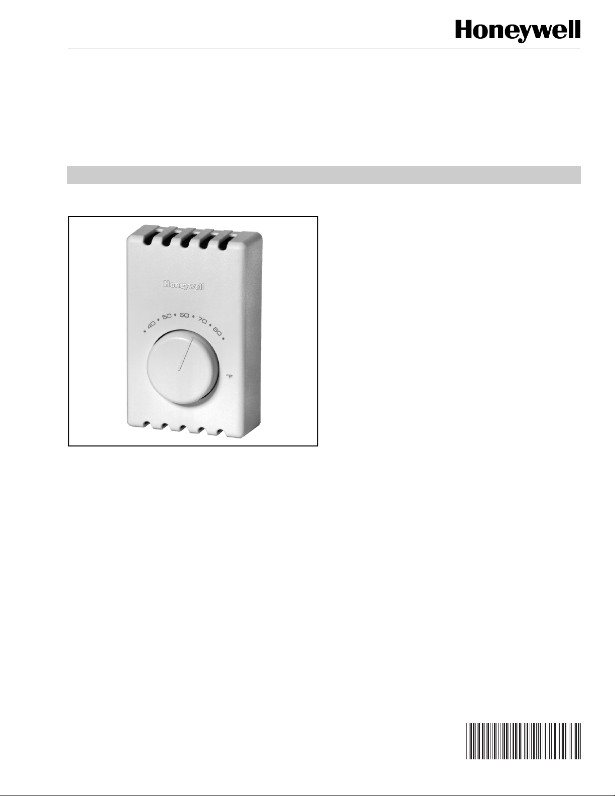
The T410A,B Electric Heat Thermostats provide line voltage
control of electric heating equipment. Snap-action switch
makes heating circuit on temperature fall.
SPECIFICATIONS
IMPORTANT
The Specifications given in this publication do not
include normal manufacturing tolerances. Therefore,
this unit may not exactly match the listed specifications. Also, this product is tested and calibrated
under closely controlled conditions, and some minor
differences in performance can be expected if those
conditions are changed. For exact engineering specifications, contact your Honeywell sales representative.
® U.S. Registered Trademark
Copyright © 2001 Honeywell • All Rights Reserved
Models:
T410A Electric Heating Thermostat: Spst switching heating
circuit makes on temperature fall.
T410B Electric Heating Thermostat: Dpst switching; makes
double line break with setting dial at OFF position; heating
circuit makes on temperature fall.
Electrical Ratings (Noninductive Resistive Rating):
22A at 120/208/240 Vac; 19A at 277 Vac.
Wiring Connections:
6 in. (150 mm) copper leadwires, suitable for connecting to
aluminum wiring if approved CO/ALR solderless wire connectors are used.
Sensing Element:
Bimetal.
Setpoint Adjustment:
Setting dial on the face of the thermostat.
Temperature Range:
40° to 80°F (5° to 25°C).
68-0145EF
T410A,B ELECTRIC HEAT THERMOSTATS
Differential:
3°F (2°C), nonadjustable.
Switching:
Micro Switch snap-acting switch.
Mounting:
Mounts directly on NEMA standard 2 x 4 in. vertical outlet box,
or 4 x 4 in. outlet box if used with ring adapter (ordered
separately), using 6-32 Robertson slotted screws.
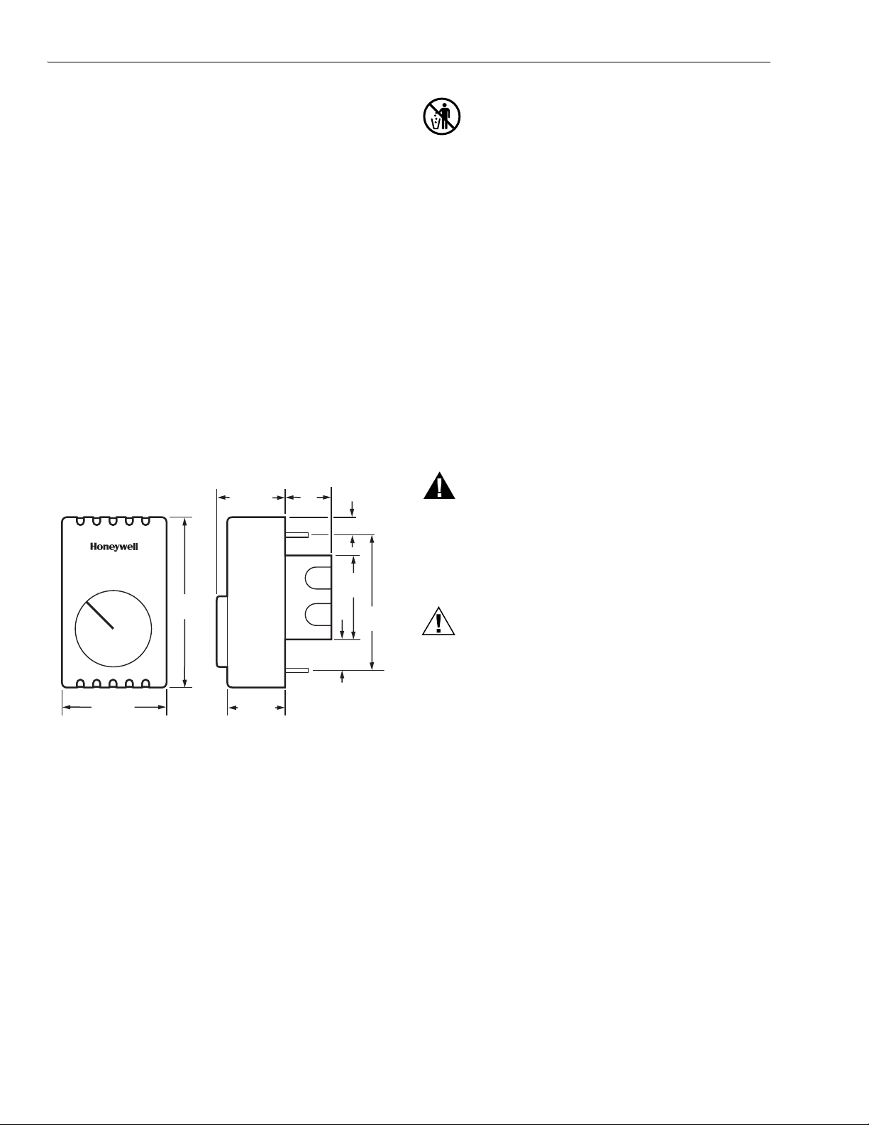
Dimensions:
See Fig.1.
Approvals:
Underwriters Laboratories Inc. Listed: File No. E47434,
Guide No. XAPX.
Canadian Standards Association Certified: File No. LR1322.
Accessory:
272804A Range Stop and Locking Cover Assembly: Includes
locking cover screws, Tinnerman clips, wrench and range
stops—two plastic pins to insert inside cover for field-selection of minimum and maximum temperature settings.
FRONT VIEW SIDE VIEW
MERCURY NOTICE
If this control is replacing a control that contains
mercury in a sealed tube, do not place your old control
in the trash. Dispose of properly.
Contact your local waste management authority for
instructions regarding recycling and the proper
disposal of an old control.
INSTALLATION
When Installing this Product…
1. Read these instructions carefully. Failure to follow these
instructions could damage the product or cause a
hazardous condition.
2. Check the ratings on the product to make sure the
product is suitable for your application.
3. Installer must be a trained, experienced service
technician.
4. After installation is complete, check out product
operation as provided in these instructions.
1-1/2 (38)
3/4
(19)
5/8 (14)
WARNING
HIGH VOLTAGE CONTROL.
ELECTRICAL SHOCK HAZARD.
Follow local codes and ordinances when installing this
thermostat. Improper handling can cause serious
0
6
•
•
7
0
0
5
•
0
4
•
•
8
0
4-1/2
•
(115)
°F
2-1/8
(54)
3-5/16
(83)
injury or death.
CAUTION
1. Disconnect power supply to prevent electrical shock
or equipment damage.
2-3/4 (70)
1-1/8 (29)
1-3/8
(35)
M5802A
2. When connecting with aluminum conductors, use
CO/ALR solderless wire connectors to avoid fire
hazard.
3. To avoid damaging the sensing element, do not
Fig. 1. T410 approximate dimensions in in. (mm).
remove thermostat cover until wiring is complete.
ORDERING INFORMATION
When purchasing replacement and modernization products from your TRADELINE® wholesaler or distributor, refer to the
TRADELINE® Catalog or price sheets for complete ordering number.
If you have additional questions, need further information, or would like to comment on our products or services, please write:
1. Your local Home and Building Control Sales Office (check white pages of your phone directory).
2. Home and Building Control Customer Relations
Honeywell, 1885 Douglas Drive North
Minneapolis, Minnesota 55422-4386
In Canada—Honeywell Limited/Honeywell Limitée, 35 Dynamic Drive, Scarborough, Ontario M1V 4Z9.
International Sales and Service Offices in all principal cities of the world. Manufacturing in Australia, Canada, Finland, France,
Germany, Japan, Mexico, Netherlands, Spain, Taiwan, United Kingdom, U.S.A.
68-0145EF 2
T410A,B ELECTRIC HEAT THERMOSTATS
Location
Install a vertical outlet box, which is used to mount the
thermostat, about 5 ft (1.5 m) above the floor in an area with
good air circulation at room temperature.
Do not install the thermostat where it may be affected by:
— drafts or dead spots behind doors, in corners or under
cabinets.
— hot air from convectors.
— radiant heat from sun or appliances.
— concealed pipes and chimneys.
— unheated (uncooled) areas such as an outside wall behind
the thermostat.
Wiring and Mounting
CAUTION
1. To avoid damaging the sensing element, handle the
thermostat with care.
2. Use a separate limit control in the heating
appliance.
3. To prevent damage to dial stop when mounting the
thermostat, turn the temperature setting dial until
the setpoint indicator is at the 12 o’clock position.
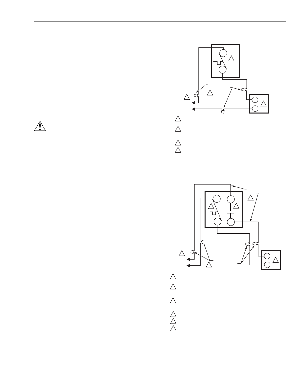
T410A
L1
4
T1
SOLDERLESS
CONNECTORS
1
L1
(HOT)
L2
POWER SUPPLY. PROVIDE DISCONNECT MEANS AND
1
OVERLOAD PROTECTION AS REQUIRED.
USE SPECIAL SERVICE CO/ALR SOLDERLESS CONNECTORS
2
WHEN CONNECTING ALUMINUM CONDUCTORS OR A FIRE
HAZARD MAY RESULT.
USE A SEPARATE LIMIT CONTROL IN THE HEATING APPLIANCE.
3
BREAKS AND REMAKES BELOW -31 F (-35 C); NORMALLY
4
THERMAL ACTIVATED. BREAKS ON TEMPERATURE RISE;
MAKES ON TEMPERATURE FALL.
2
ELECTRIC
HEATER
3
M5811B
Fig. 2. Typical wiring connections for T410A.
Replacement Applications
1. Disconnect power to the thermostat to prevent electrical
shock or equipment damage. All wiring must comply
with local electrical codes and ordinances.
2. Remove the old thermostat from the wall, taking care
not to damage the wiring insulation.
3. Check the old wire insulation for cracks, nicks or fraying.
If necessary, apply approved electrical tape to insulate
old wires or replace with new wires.
4. Do not remove the T410 Thermostat Cover. Using wire
connectors approved for No. 12 wires, make line voltage connections directly to the leadwires on the thermostat. See Figs. 2 and 3 for typical wiring connections.
5. Prebend and push solid wires into the outlet box.
6. Remove thermostat cover by grasping the top and bot-
tom cover edge and pulling it outward away from the
thermostat base.
7. Turn the temperature setting dial so the setpoint indica-
tor is at the 12 o’clock position to prevent damaging the
dial stop.
8. Mount the thermostat on the outlet box. Tighten the two
mounting screws (included) to secure the thermostat,
taking care to avoid excessive pressure on the setting
dial. See Fig. 4.
T410B
L1
L2
3
T1
T2
1
L2
L1
(HOT)
1
POWER SUPPLY. PROVIDE DISCONNECT MEANS AND
OVERLOAD PROTECTION AS REQUIRED.
2
USE SPECIAL SERVICE CO/ALR SOLDERLESS CONNECTORS
WHEN CONNECTING ALUMINUM CONDUCTORS OR A FIRE
HAZARD MAY RESULT.
3
BREAKS AT POSITIVE OFF AND REMAKES UNDER –31 F (–35 C);
NORMALLY THERMALLY ACTIVATED. BREAKS ON TEMPERATURE
RISE; MAKES ON TEMPERATURE FALL.
4
USE A SEPARATE LIMIT CONTROL IN THE HEATING APPLIANCE.
5
BREAKS AT POSITIVE OFF ONLY; NOT THERMALLY ACTIVATED.
6
DO NOT CONNECT GROUNDED CONDUCTOR (NEUTRAL) ON
120 OR 227V CIRCUITS. INSULATE AND TAPE OR CUT OFF
RED WIRES IF UNUSED.
SOLDERLESS
CONNECTORS
2
RED
WIRE
6
5
ELECTRIC
HEATER
M5812B
4
Fig. 3. Typical wiring connections for T410B.
3 68-0145EF
 Loading...