

Honeywell RP908A 1039, RP908B Series, RP908A 1047, RP908A 1013, RP908A 1054 Service Data
...Page 1
GENERAL
DESCRIPTION
The RP908A and B are force balance pneumatic
amplifiers, with adjustable proportional band, for use as
Controllers in HVAC systems,
The RP908 is no longer being manufactured. There is
an RP920 model available for all RP908A and B applications. Refer to Application Replacement Listing in the
REPAIR section.
APPLICATION
RP908A
RP908A &
B
PNEUMATIC CONTROLLERS
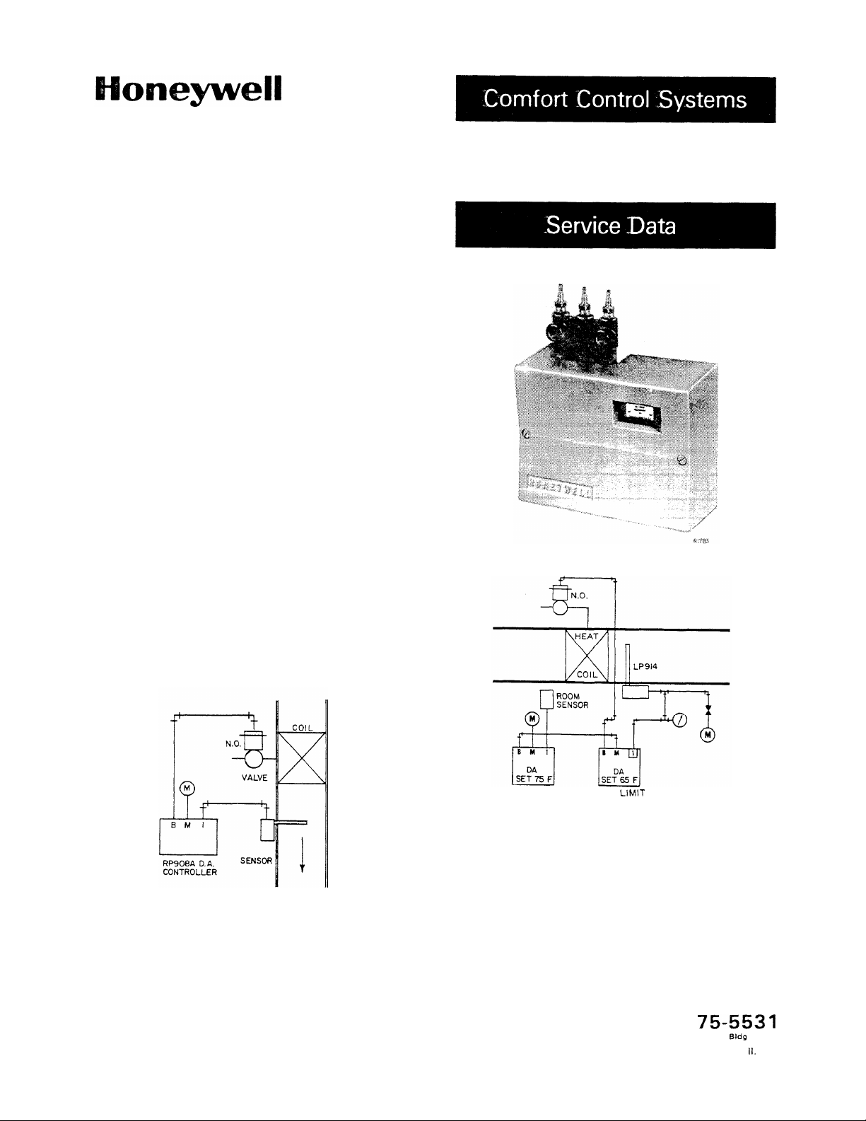
The RP908A, in conjunction with a remote sensor,
provides direct or limit control in air conditioning control systems, with or without remote control point
adjustment (CPA). It may be adjusted for either direct or
reverse acting operation. Refer to Figures 1 and 2 for
these applications.
5737-2
Fig. 1. Typical RP908A Primary Control of Normally
Open Valve.
PRIMARY
CONTROLLER
LIMIT
LOW
CONTROLLER
5759-2
Fig. 2. Typical RP908A Low Limit Control.
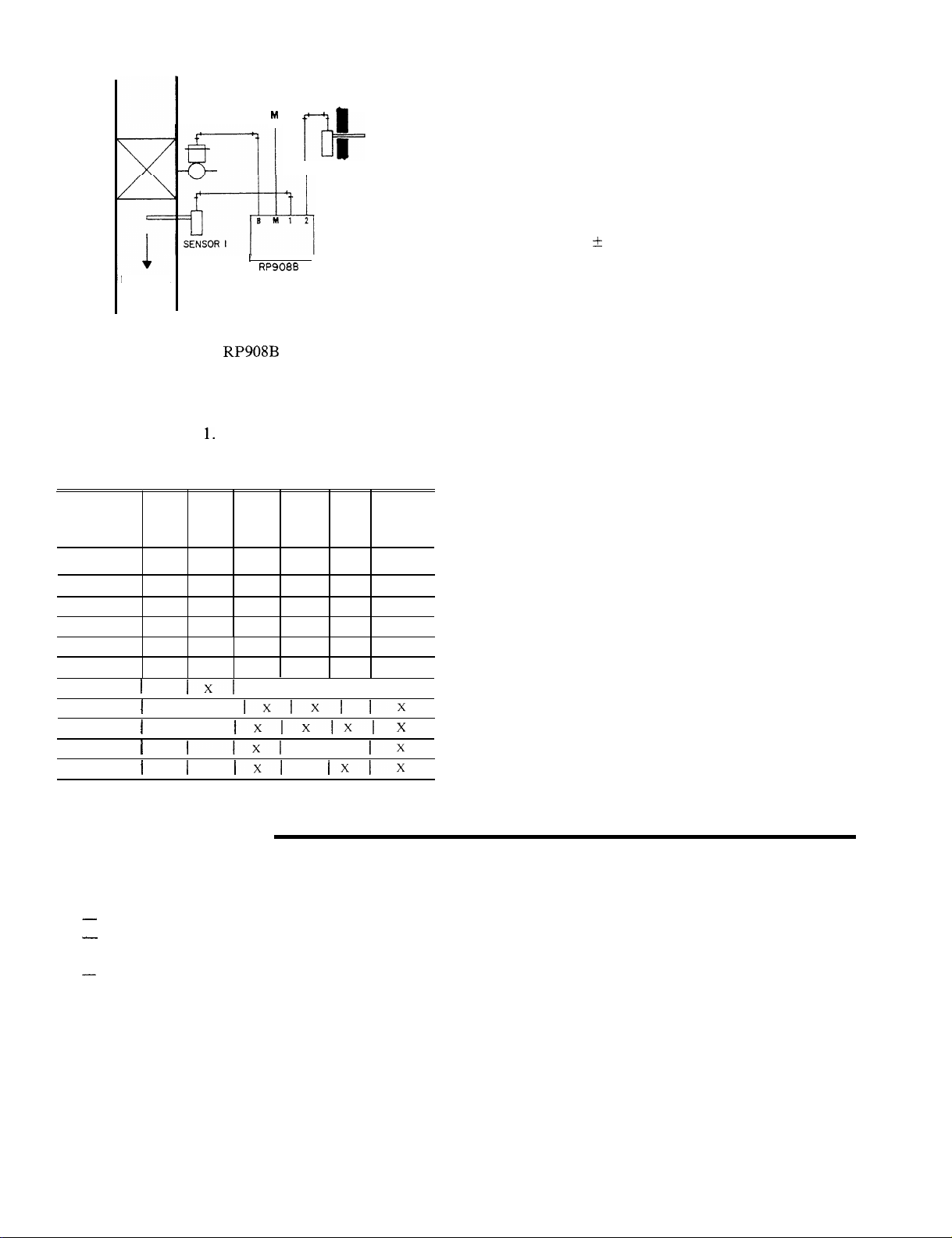
RP908B
The RP908B dual input Controller is applied to compensating systems by using an additional compensating
signal to change the control point of the Controller (Fig.
3). Temperature, humidity, pressure, or dewpoint may
be controlled by using the appropriate sensors,
Rev. 6-84
Form No
75-553 1
Commercial Bldp
MLFTAB:
Group
111
C. 6.
Page 2
1
DISCHARGE
hl
Q
I
RP908B
I
I
I+
SENSOR 2
D.A.
J
5760-2
SUPPLY AIR PRESSURE: 18 psi (124
MAXIMUM SAFE AIR PRESSURE: 25 psi (172
kPa)
nominal.
kPa).
AMBIENT TEMPERATURE LIMITS: 40 to 120F (4 to
9OC).
PROPORTIONAL BAND:
2-1/2
to 40 percent of pri-
mary sensor span, field adjustable.
AUTHORITY: 10 to 200 percent of primary sensor span,
field adjustable.
REMOTE CPA:
-t
10 percent of sensor span.
OPERATION
RP908A
Fig. 3. Typical RP908B Application.
SPECIFICATIONS
MODELS: See Table
Table 1. RP908A and B Model Listing.
Single
Model
RP908A
1005 X
RP908A
1013 X
RP908A
1021 X
RP908A
1039 X
RP908A
1047
RP908A
1054 X
RP908A
1042
RP908B
1003
RP908B
1011
RP908B
1029
RP908B
1037
Input Limit
1
I
I
I
I
1.
Single
Input
IXI
I
I
11x1
I
Dual With
Input Cover
X
I I I
lxlxl
Ixlxlxl
I
1x1
X
X
X
X
With
CPA
X
X
Ixlx
With
Calibration
Knob
X
X
X
X
X
X
Ix
x
Ix
When used in a heating system with the Controller set
for direct action, a drop in temperature at the sensor
lowers the branchline pressure, opening the valve to
increase the flow of heating medium to the coil (Fig. 1). If
the CPA model is used, an increase in air pressure on the
CPA port raises the setpoint of the Controller and a
decrease lowers it.
Used as a low limit Controller, the
RP908B
reduces
branchline pressure from the primary Controller, opening a heating valve to maintain discharge temperature at
setpoint (Fig. 2).
RP908B
Operation is similar to RP908A. However,
an
increase
in outdoor temperature causes the compensating (outdoor) sensor to reset the control point of the Controller
to raise the branch line pressure (Fig. 3). The resulting
change in branch line is dependent on the authority setting on the Controller.
MAINTENANCE
EQUIPMENT REQUIRED
-
Plastilube 311057 for O-rings, screw threads, etc.
-
Molycote or similar commercial powdered lubri-
cant for pivots and plungers in units with CPA.
-
0 to 30 psi test gage (if gages have not been installed
in system).
GENERAL
The only preventive maintenance necessary is an
annual visual check for leaks, loose fittings, etc, and an
operational and calibration check.
75-553 1
OPERATIONAL CHECK
Check main air pressure for 18 psi (124 kPa) at Controller. For models with manual CPA adjustment, move
CPA switch up and down and observe the action of the
Controller. If the system’ does not have CPA, the sen-
sor(s) may be disconnected and the port plugged so that
pressure may be slowly built up, causing the Controller to
operate from one extreme position to the other. Bleeding
this pressure slowly causes the Controller to operate in
the opposite direction. The main lever should move
smoothly, and the branchline pressure should change
gradually in the proper direction.
2
Page 3
CALIBRATION CHECK
RP908A
Change the
sensor temperature if the two do not already match. The
branchline pressure should be at its calibration pressure
of 8 + 1 psi (55
drawings. If recalibration is necessary, see CALIBRATION,
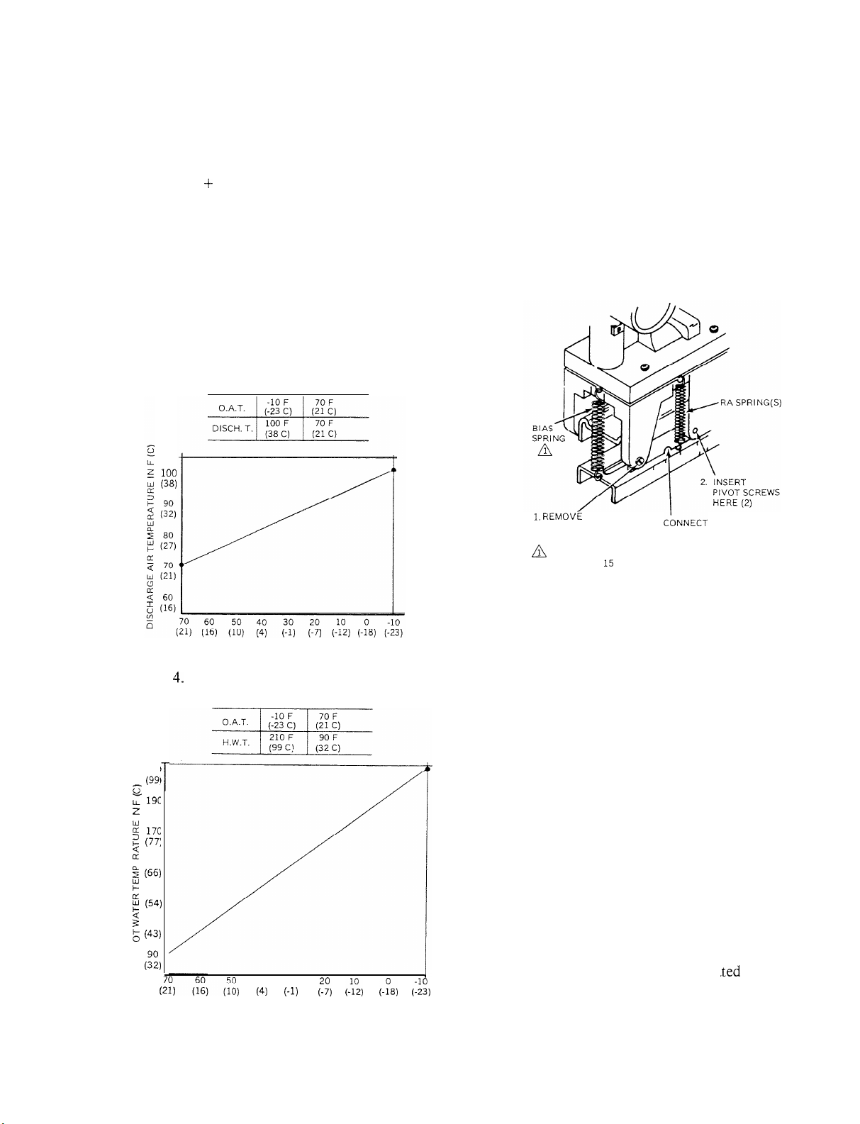
RP908B
Determine the existing calibration temperature from
the reset schedule on the job drawings. Draw a straight
line on graph as shown in Figure 4. Measure the temperature at the Port 2
sor temperature (Fig. 5). Measure temperature at Port 1
sensor location. This temperature must agree within two
100
(38)
setpoint
-t-
7
kPa)
sensor.
of the Controller to the existing
unless otherwise noted on job
Find corresponding Port 1 sen-
percent of the sensor range span and the branchline pressure must be within the operating range of the controlled
device. If recalibration is necessary, see CALIBRATION.
CHANGE FROM DIRECT TO REVERSE
ACTING
The change from direct to reverse acting is made by
following the three steps listed in Figure 6.
OUTDOOR AIR TEMPERATURE IN F(C)
20884
Fig. 4, Typical Discharge Air Reset Schedule.
21c
(99:
T
??
:
19c
z
(88
2
17c
2
(77:
;:
w 150
ii
(66)
?
[L
130
p
(54)
s
110
g
(43)
I
(Zi,
40 30
OUTDOOR AIR TEMPERATURE IN F (C)
(4)
(-1)
(770)
(-:“z,
(-:8) (::i)
Fig. 5. Typical Hot Water Reset Schedule for
Radiation Systems.
20885
1.
RENlOVE PIVOT
SCREWS (2)
A
DISCONNECT WHEN PROPORTIONAL BAND (PB) IS
LESS THAN 15 PERCENT, REGARDLESS OF ACTION.
3.
CbNNECT
TO NOTCHES (2)
RA SPRINGS (2)
4707-l
Fig, 6. Set-Up for Reverse-Acting Operation.
ADJUSTMENTS
PROPORTIONAL BAND
If the original setting shown on the job drawings must
be changed:
1. Loosen the Proportional Band Adjustment Knob
(Fig. 7) and slide the Proportional Band Indicator
to the desired setting.
NOTE: When a proportional band of more than
I5 percent is used, fasten the Bias Spring
to the Lever Assembly (Fig. 6). This spring
is left unconnected if proportional band is
15 percent or less.
I
2. The Controller must be recalib
proportional band is changed.
ra
.ted
whenever the
75-553 1
Page 4
REMOTE CONTROL POINT
A pressure change from 3 to 13 psi (21 to 90
kPa)
in the
remote CPA port changes the control point proportionately by 20 percent of the sensor span.
1 (and Port 2 if RP908B is used). If the reset signal on an
RP908B is produced by the output of a room thermostat
or pressure control, a
Port 2. Otherwise, the scale range on the
30-psi
gage must be installed in
gage should
match the range of the sensor for Ports 1 and 2.
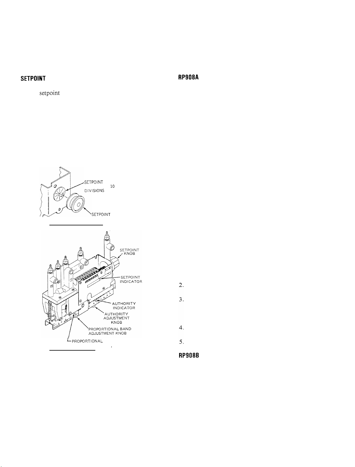
SETPOINT
The
setpoint
is raised by turning the
Setpoint
Knob
(Fig. 7) counterclockwise. This increases the force from
the
setpoint
spring on the lever assembly so that a greater
force from the sensor chamber is required to cause an
increase in branchline pressure.
The
setpoint
It has 10 marked divisions, each equaling
screw has a vernier for fine adjustment.
l/2
percent of
the sensor span (1 degree F per division for a 200-degree
sensor span, or 20 turns for the whole span).
SETPOINT
SCREW WITH 10 MARKED
DiVISIONS
CONTROLLER WITHOUT CPA
ADJUSTMENT
SETPOINT
KNOB
RP908A
There are two methods of calibrating the RP908A
when 18 psi (124
kPa)
main air is supplied to the Control-
ler and the internal restriction is not blocked.
CALIBRATION USING AN ADJUSTABLE
RESTRICTION
1,
Install the proper scaleplate on the Controller if not
already installed.
2.
Disconnect the Port 1 sensor and connect an adjustable restriction to Port 1.
Choose a
3.
setpoint
and adjust the restriction until the
gage in Port 1 shows this setpoint.
Turn the
4.
reads 8 psi (55
setpoint
knob until the branchline pressure
kPa).
This is standard calibration. On
some applications, the calibration branchline pressure
may be set at a different point that relates to the spring
range of the device being operated.
Move the scaleplate until the
5.
setpoint
indicator agrees
with the chosen setpoint, and tighten.
6.
Disconnect the adjustable restriction and reconnect
the sensor.
LPROPORTIONAL
CONTROLLER WITH CPA
BAND INDICATOR
.
20887
Fig. 7. RP908 Adjustment Locations.
CALIBRATION
GENERAL
Always calibrate with 18 psi (124
sure. On CPA models, set CPA to 8 psi (5.5
30-psi gage must be installed in the branchline port
during calibration and a temperature, humidity, or pressure gage matching the sensor should be installed in Port
kPa)
main air pres-
kPa).
A 0 to
CALIBRATION WITH GAGES
1. Install
30-psi
match Port
gages in Ports 1 and B. Port I gage must
B.
Install proper scaleplate on the Controller if not
already done.
Turn the
psi (55
setpoint
kPa)
knob until branchline pressure is 8
or other selected calibration pressure (see
Step 4 of CALIBRATION USING AN ADJUSTABLE RESTRICTION).
Move the scaleplate until the
setpoint
indicator is at
the reading shown on the Port 1 gage and tighten.
Adjust the
setpoint
to the desired control setting.
RP908B
The only method of calibrating the RP908B is to use
an adjustable restriction. If the settings are known, proceed to Step 1 of RP908B CALIBRATION PROCEDURE. If the settings ‘must be calculated, read the
following and calculate as shown. Authority Calculator
No. 813 may be used to simplify these calculations.
Although these examples are shown for a hot water reset
system, the formulae also apply to other systems-
75-553 I
4
Page 5
Two separate parameters must be known in order to
properly calibrate a reset system, Reset Schedule and
Throttling Range. Proportional Band and Authority
may be calculated from these parameters
RESET SCHEDULE
The reset schedule is plotted by determining the outdoor air temperature at which designed maximum heating water temperature is needed and the outdoor air
temperature at which no heating is required.
THROTTLING RANGE (TR)
Throttling Range indicates the change in water temperature at the sensor to cause the valve to move from
fully open to fully closed (full heat to no heat). It is desirable to have a throttling range as narrow as possible for
efficient control and yet wide enough to produce stable
operation. A throttling range of
mended trial setting. If the system will not stabilize after
being in operation for a short period of time, the throttling range should be increased (this requires recalculation of the proportional band, authority, and
recalibration). An unstable system can be recognized by
frequent, repetitive changes in branchline pressure,
known as hunting or cycling.
a
10F (5C)
is a recom-
Where:
TR = Throttling Range
AT1= Change in Hot Water Temperature
AT2
= Change in Outdoor Air Temperature
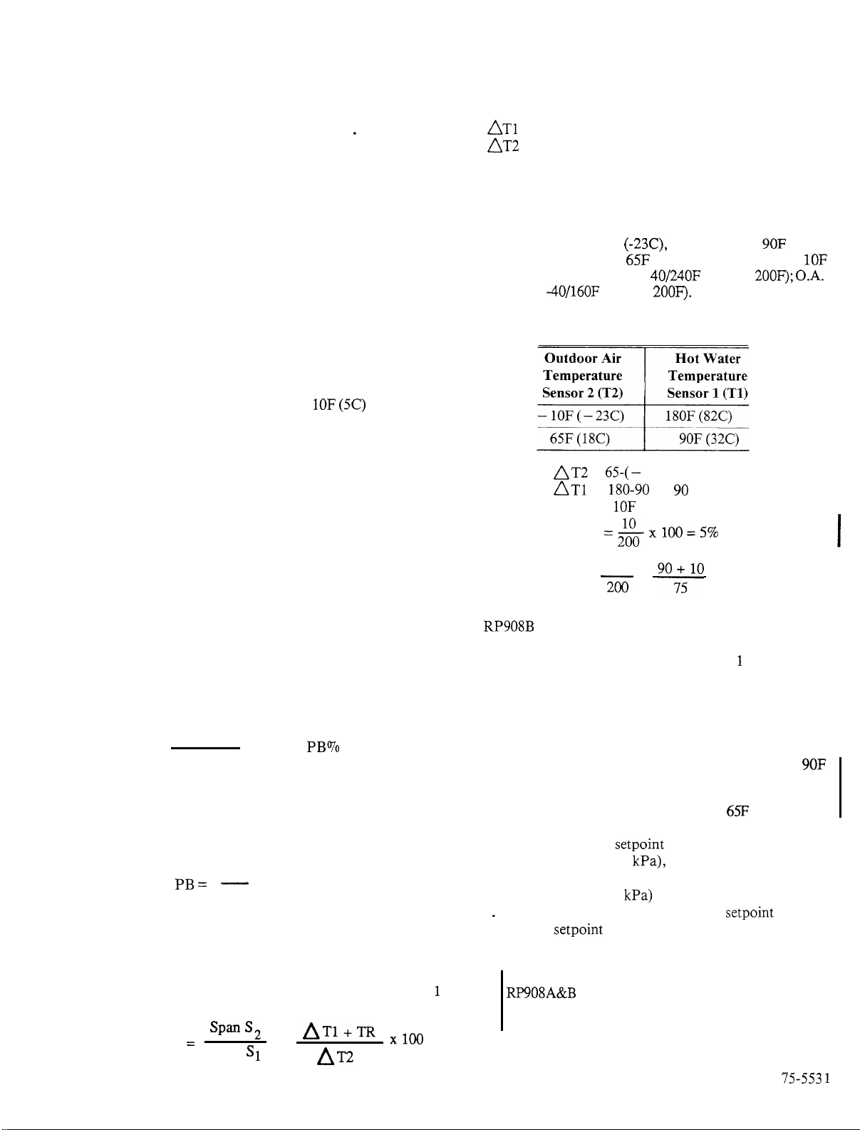
EXAMPLE:
Determine settings for a system where hot water should
be controlled at 180F (82C) when outdoor air
temperature is -lOF
when outdoor air is
(5C). Hot Water Sensor
Sensor
-40/160F
AT2
ATI
TR =
PB = &
(-23C),
65F
(18C). Assume a TR of
40/24OF
(Span =
Reset Schedule
=
65-(-
10) = 75
=
180-90
=
10F
x100=5%
and reduced to
(Span =
2OOF).
go
9OF
200F);
(32C)
0-A.
IOF
When the throttling range has been selected, it must be
converted to a proportional band value that can be set on
the Controller.
PROPORTIONAL BAND (PB)
Proportional Band is similar to throttling range except
it is expressed in terms of percent of temperature change
rather than degrees. Proportional band can be determined by using the following formula:
TR
Sensor Span
EXAMPLE:
When a sensor having a 200-degree span is used and a
IO-degree TR has been selected:
PB =
200
AUTHORITY
Authority indicates the amount of effect that the change
in outdoor air temperature will have on the control point.
The formula must take into account
and Sensor 2. The complete formula is:
Authority
=
Span S,
Span SI
x 100 = PB%
10
-
x 100 = 5%
the
spans of Sensor
A~l+m xloQ
X
Al-2
1
Authority =
RP908B
I. Install the scaleplate matching the Port I sensor on the
2.
3.
4
5
CALIBRATION PROCEDURE
Controller if not already done.
Disconnect the sensors to Ports 1 and 2 and connect an
adjustable restriction to each port. If an external main
has been connected to the sensor line, install the
adjustable restriction on the sensor side of the tee.
Select the low end of the Sensor 1 schedule or
(32C). Adjust the No. 1 restriction until the Sensor 1
gage reads that temperature. Also set Sensor 2 at “low
end” of reset schedule, in this example
Set the authority and proportional band into the Con-
troller. Adjust the
gage reads 12 psi (83
closed” pressure if the valve has other than a standard
4 to 11 psi (28 to 76
.
Move the scaleplate until the desired
with the
ler is now in calibration.
REPLACEMENT PAGE FOR:
RP908A&B
Service Data
75-5531 6-84 II. C. 6.
setpoint
200
2oo
indicator and tighten. The Control-
Pneumatic Controllers
90;5IO
x
setpoint
kPa),
kPa) spring range.
x 100 = 133%
knob until the branchline
or until it reads the “valve
65F
(18C).
setpoint
8-88
90F
lines up
75-553 1
Page 6

TROUtBLESHOOTlNG
Before troubleshooting the RP908, make a visual
check of the Controller to see that springs and pivots are
connected
properly
for the application. If the RP908 is
MEASURE CONTROLLED
VARIABLE. COMPARE
WITH SENSOR 1 GAGE
READING.
REMOTE
CPA ONLY
-
4
still not working properly, refer to Fig. 8, RP908
Troubleshooting Flowchart.
CONTROLLER
NOT CONTROLLING
ADJUST PRV OR
YES
CHECK VALVE OR DAMPER
FOR CLOSEOFF, LEAK, OR
MALFUNCTION. CHECK
FOR CLOGGED RESTRICTIONS,
FILTERS. SCREENS. SENSOR
LINE AIR LEAK, BAD SENSOR,
OR GAGE OUT OF CALIBRATION.
CORRECT AS NECESSARY.
RF’908
I
I
RECONNECT TO
l
I8
PSI MAIN.
RECALIBRATE
AND RECHECK
CHECK DEVICE
OPERATION.
REPLACE IF
NECESSARY
1
CHECK BRANCH
LINE PRESSURE
TEST BRANCH
LINE FOR
LEAKS. REPAIR
IF NECESSARY.
CHECKOPERATION.
Fig. 8. RP908 Troubleshooting Flowchart.
CHECK OPERATION
TEST TUBING
FOR LEAKS
REPAIR IF
NECESSARY
LUBRICATE CONTROLLER
PIVOT POINTS. REPLACE
CONTROLLER IF LIBRICATION
DOESN’T HELP
h
1
CONTROLLER
NOW MATCH
REPLACE SENSOR,
CHECK OPERATION.
I
x2593
I
75-553 1
Page 7

REPAIR
RP908 DISASSEMBLY PROCEDURES
1.
Disconnect system air. Loosen the two Screws and
remove Cover (Fig. 9, Part 1).
2,
Loosen the three Screws securing the Controller to
the Backplate, and move Controller to a bench,
If replacing the CPA Seal, it is necessary to do this
while the Bracket is attached to the Body
easy to rip the CPA Seal if the
Assembly is loose. See Step 15, CPA Models.
r---cAuT1oN------l
a.
Remove the four Screws securing the Bracket to the
Body (Fig. 9, Part 2).
4.
Remove the four Screws securing the Manifold (Fig.
9, Part 3).
5.
Lift the Manifold from the Body.
6.
Remove and discard the Gasket, if replacing.
7_
Note the location of the Filters and Restriction(s),
The RP908A may have two or three Filters (depending on model), and the
four Filters. Some Controllers may have a field-
installed Blank Orifice in place of a Restriction, Filter, Screen, and Washer. If this Blank Orifice is
required, the job drawing will show a box drawn
around the port of the
NOTE: Serviceline Repair Kit 14002696-001 is
available for order. This kit contains one
Gasket, four O-Rings, four Screens, two
Restrictions, four Filters, and four
Washers
8.
Remove the Washers, Filters, Screens, Restriction,
and O-Rings, if replacing, and discard.
9.
Remove Blank Orifice, if installed. Install replacement parts in reverse order,
IO.
For Body repair, first disconnect the Bias Spring and
the two Reverse Acting Springs at the lower attachment point.
111.
Remove the two Pivot Screws securing the Lever
Assembly to the Body. Set Lever Assembly and
Screws aside.
12.
Remove the two Screws securing Upper Lever
Assembly. Set Upper Lever Assembly and Screws
aside.
13.
Remove the two cross-head Screws from the Cover
Assembly to replace any parts in the Cover
Assembly,
RP908B
RP908
e
Setpoint
may have three or
to be blocked.
It is very
Screw
14.
For replacement of the Proportional Band Adjustment Knob, simply unscrew from the Indicator
Assembly.
15.
Non-CPA Models:
Remove the
point Spring,
then come right out.
CPA Models:
a. Loosen the two cross-head Screws and remove the
CPA Housing (Fig. 9, Part
the Seal while the bracket is still attached to the
Body. The Seal should be removed and then the
Bracket detached from the Body to remove the
Setpoint
point Screw Assembly.
b. Remove the two cross-head Screws from the end
of the Authority Adjustment Lever Assembly.
Remove the two Screws from the front and back
of the Bracket to remove the Body Assembly that
is situated over the Authority Adjustment Lever
Assembly.
16,
Assemble RP908 in reverse order and turn on system
air.
17.
Make all Settings and Adjustments applicable to
model according to job drawings. Perform Operational Check and Calibrate (see MAINTENANCE
section).
Setpoint
Knob,
Knob (Fig. 9, Part 4). The
Setpoint
Nut, and Setpoint Screw will
4),
Setpoint
Spring, and/or the
Set-
Carefully remove
Set-
REPLACEMENT OF RESTRICTION
WlTH BLANK ORIFICE
The Internal Restriction must be replaced with a
Blank
external source of restricted air, This occurs when the air
supply to the M Port of the Controller is varied by other
controls, or when a single sensor is connected to more
than one Controller. To replace the Restriction with a
Blank Orifice, proceed as follows, referring to Figure 9,
Part 3.
Restriction is not blocked, do not plug the unused port
but leave it open to avoid building up to mainline pres-
sure in the sensor chamber. Two limit models of the
RP908A
Orifice identified by a red Manifold. When field install-
ing a Blank Orifice, the Manifold and job drawings
should be marked, indicating that the Restriction is
blocked.
Grifice
1. Remove the Manifold and Gasket.
2. Remove the Port 1 O-Ring, Restriction, Screen,
Filter, and Washer. Install Blank Orifice 316125.
3. Reassemble the O-Ring, Gasket, and Manifold,
carefully noting orientation of the Gasket,
When using only one port of an
when the sensor is supplied with an
RP908B
were provided with a factory-installed Blank
and the
75-553 1
Page 8

REPLACEMENT OF RP908 WITH
RP920
Table 2 lists specific model numbers of the RP920 that
are direct replacements for the RP908.
PARTS AND ACCESSORIES
Table 2. Application Replacement Listing.
PARTS LIST
Refer to Figure 9, Parts 1 through 4, and Table 3 for
available replacement parts for the
trollers. Those items listed without a part number are no
longer available.
Fig. 9
Ref. No.
4
5
6
7
8
9
10
11
12
Part Number
3.5 1277-00767
3
15299-00767
-
315282
315255
315263
3 15293-00605
3
15740-00062
315284-00101
315204A
3
16205A
-
14002696-00 1
14004146-001
312826
315249
3 15245
315253
RP908A
Backplate
Backplate
Screw, Backplate (3) No. 6-32 x
Cover,
Cdver, RP908B
Cover,
Screw, Cover (2)
Screw, Bracket
Manifold,
Manifold,
Manifold, RP908A Limit (RED), with Check Valve 315918
Screw, Manifold, 8-32 x 1
Repair Kit-includes
Screens, 4 Filters 9 and 4 Washers)
Gasket
O-Ring
Restriction
Screen
Filter
and B Con-
Table 3. RP908 Parts List.
(RP908A)
(RP908B)
RP908A
RP908A,
without CPA
without CPA
B with CPA
(4))
RP908A
RP908B
Description
l/4
Panhead
No. 8-32 Oval Undercut Head
l/16
Panhead
Iteas*
through 13 (1 Gasket, 4 O-Rings, 2 Restrictions, 4
75-553
1
8
Page 9

Fig. 9
Ref. No.
Part Number
Table 3.
RP908
Parts List. (Continued)
Description
13
-
-
14
15
16
17
18
19
20
21
22
23
24
25
26
27
28
29
30
31
32
33
34
3.5
36
37
38
39
40
41
42
43
44
45
46
47
304963-001
316165A
316165B
-
-
3 15224
303634
-
3 15240
315233
316155A
3 15239
-
304721
3 15247
-
3
15280A
3
15280B
3
1528OC
3 15242
-
14001848-001
14001258-001
315260-00101
-
316157
3 15285-00605
-
3 15252A
-
-
14001846-001
3 15278-00062
3 152 1 o-00062
315215-00021
315214-00606
-
316162A
-
-
-
Washer
Body Repair Assembly for
Body Repair Assembly for
Tube,
RP908B
RP908A-includes
RP908B-includes
Items 15 through 26
Items 14 through 26
Body, RP908A, B
Pivot Screw (2)
Spring
Lever Assembly
Screw (2)
Gasket
Cover Assembly
Nut
Screw, 8-32 x 1 l/ 16
Panhead
Tension Nut
Tension Screw, PB Adj.
Upper Lever Assembly
Lever Assembly
Lever Assembly
Lever Assembly
(RP908A)
(RP908A
(RP908B)
wit
h
CPA)
Proportional Band Adjustment Knob
Indicator Assembly
Bias Spring
Reverse Acting Spring (2)
CPA Housing (CPA models)
Screw, 8-32 x
l/2
Fillister Head (CPA Models)
CPA Seal (CPA Models)
Scaleplate
Screw,
Body Assembly
RP908B,
8-32 x 5/16 Oval Head (3)
(RP908B)-includes
Diaphragm 3 15225, Washer 304573-124, and
Connecting Tube O-Ring 3 10779
Screw,
Authority Adjustment Lever Assembly
Setpoint
Setpoint
Setpoint Screw,
Setpoint
Setpoint
Setpoint
Setpoint Screw Assembly (CPA Models), with Aluminum Plug 3
RP908B, 8-32 x
l/4 Panhead
Knob (non-CPA models)
Screw,
Spring,
Spring,
RP908A
(non-CPA models)
RP9CX3 1003
RP908A
RP908A
(non-CPA)
(CPA) and
and
Nut
(2)
(RP908B)
RP908B
RP908B
1029
15243-101
Bracket
Screw, 6-32 x
3/8
Panhead
Nut (Tinnerman Clip)
75-5531
Page 10

Page 11

I
I
I
_--_
0
16
(lo-J
-
PORT 2,
>!i+PORT
I
I
I
i
\
Fig. 9 (Part 3 of 4). RP908 Controller-Exploded View.
11
I
J
w
x2101
75-553 1
Page 12

Fig. 9 (Part 4 of 4). RP908 Controller-Exploded View.
20888
ACCESSORIES
1
_
Scaleplate Decals.
Table 4 lists the scaleplate decals that are available for
the RP908.
2. Blank Orifice 316125-00606 (field installed).
3. Self-rewinding Rapid Adjustment Knob 3
4. Gages.
Table 5 lists gages that are applicable for use with the
F
RP908
75-553
1
16479A,
Table 4. Scaleplate Decals
No. 315993A:
Oto2OOF
40 to 160F
40 to 240F
50 to
1OOF
3 to 15psig
0.2 to 1 .O
-
20 to 80C
-
40 to 60C
kg/cm2
5 to 105c
No. 316005: - 1 to
No l 316089:
12
-25 to
lOto4OC
WARMER/COOLER
15 to 85% RH
-
20 to 80F
-
30 to 30F
25 to 125F
-5to55C
15 to 75% RH
65 to 95% RH
’
6
in.H20 (D.A.)
1SOmm Hz0
b
(D.A.)
Page 13

Part No.
(l-1/2
in. dia.
back
corm.
l/8
NPT)
14000786-001
14000786-002
305929
305932
30593
1
305934
305986
305987
305930
305933
305972
305973
14000786-0051 15 to 85
14000786-003[ 15 to 75
14000786-0041 65 to 95
305988
Scale Range
Temperature
25 to
I
1 -5
to 55C
1 -4oto
160F
1
-4Oto60C
t
40 to 240F
5to 115c
I
1
-2Oto80F
1
-3oto30c
1
Oto 200F
1
20to 80C
1
50to
1OOF
1
lOto38C
Relative Humidity
40 to 75F TP925A1018
Table 5. Gages.
I
125F
I
I
1
LP914
1
LP914
I
LP914
I
1
LP914
1
LP914
1
LP915
I
LP915
1
TP924, TP974, TP925
1
TP924, TP974, TP925
-
-
-
Dewpoint
1
HP971
1
HP971
I
For Use with Sensor
LP914
LP914
LP914
HP971
305965
305615
305616
305617
305618
305624
305619
305625
305620
305626
I
I
50to
I
1
75 to 125 mm of WC I PP905
I
I
lOOto
0 to30psi
- 1to1 in.ofWC
0 to 2 in. of WC
1 to 3 in. of WC
2to4in.ofWC
IOOmmofWC
3to5in.ofWC
4to6in.ofWC
150mmofWC 1 PP905
PP9C
I
PP905
PP905
PP905
I
PP905
1
PP905
I
PP905
13
75-553 1
Page 14

ALABAMA
Bxmingham, AL
(2051
323.2431
Mobile, AL
(800) 633-l 644
ALASKA
Anchorage, AK
(907) 2740551
ARIZONA
Phoenlw,
AZ
(602) 8614512
Tucson, AZ
(602) 7954209
AR KANSAS
LIttIe Rock, AR
1501) 6644070
CALIFORNIA
Irwne.
CA
(714)
557-6392
Los Angeles, CA
(213)
7266161
Sacramento, CA
(916) 485.2221
San
Dlego,
CA
(714) 292.5311
San Jose, CA
(415)
957-2674
San
Franc~sco,
DC
827.3705
CA
(415) 957.2674
COLORADO
Denver, CO
(303) 7796295
CONNECTICUT
Hartford, CT
(203) 549.3800
DELAWARE
Wllmlngton, DE
(302) 762.3100
DISTRICT OF COLUMBIA
WashIngton
(703)
FLORIDA
JacksonwIle, FL
(904) 3966971
Miami, FL
(305) 592.8140
Orlando, FL
(305) 894-3131
Tampa, FL
(813) 877-6426
GEORGIA
Atlanta, GA
(404) 982.2495
HAWAII
Honolulu, HI
(808) 537-5514
IL
.LINOIS
Chrcago
1312)
478-9266
ChIcago
(312) 568-4200
Elgln,
IL
(312) 697.7880
Peona.
1309)
692-0610
INDIANA
Fort Wayne, IN
(219) 482.9654
Indianapolls, IN
(317) 243.0831
IOWA
Davenport, IA
(319) 359-3441
Des Moines, IA
(515) 288-3601
KENTUCKY
~ouw~lle, KY
(502) 459-5970
LOUISIANA
Baton Rouge, LA
(504) 9248626
New Orleans, LA
(504) 456-7232
Shreveport, LA
(214) 387-5467
North, IL
South (Lar
IL
Irlngl,
I
MAINE
Ponland, ME
(2071
775-3501
MARY LAND
Baltimore, MD
(301) 828-0900
MASSACHUSETTS
Boston, MA
(617) 962-0250
MICHIGAN
Detrort, Ml
(313) 478.1600
Grand
RapIds,
1616)
2474811
Saginaw,
MI
(517) 792.8707
MINNESOTA
Duluth, MN
(612) 770-8557
Mmneapol~s,
MN
(6121
830-3880
St. Paul, MN
(6121
770-8557
MISSISSIPPI
Jackson, MS
(601) 982-2090
MISSOURI
Kansas
City,
MO
(816) 35842GO
St
LOUIS,
MO
(314) 576-2635
NEBRASKA
Omaha, NE
(402) 331-3200
NEW HAMPSHIRE
Bedford, NH
(603)
6256502
NEW JERSEY
Mr
Laurel, NJ
(609) 234-2224
Pars~ppany,
NJ
(201) 263.2225
WestfIeld,
NJ
(201) 233.9200
NEW MEXICO
Albuquerque, NM
(505)
NEW YORK
Albany, NY
(5 18)
Buffalo, NY
(716) 689-0200
Brooklyn, NY
(212l3924300
Manhattan, NY
(212) 3924300
MI
Rochester, NY
(716) 424-2700
Syracuse, NY
(315) 4514000
White
(914) 948-7511
Woodbury, NY
(516) 931.1506
NORTH CAROLINA
Charlotte, NC
(70413644770
Greensboro, NC
(919) 292-1556
NORTHDAKOTA
Fargo, ND
(701) 2354221
OHIO
Akron, OH
(216) 733.2244
Cmclnnatr. OH
(513) 745-7151
Cleveland, OH
(216) 459.6057
Columbus, OH
(614) 4865971
Dayton, OH
(513) 2374035
Toledo, OH
(419) 473.9721
8841070
456.7000
Plams,
NY
OKLAHOMA
Oklahoma
Cw.
(405) 848.2811
Tulsa, OK
(918) 437-5934
OREGON
Eugene, OR
(503) 485-2251
Portland, OR
(5031
245-0731
PENNSYLVANIA
Harrrsburg,
PA
(717) 564-8000
Phrladelphla,
PA
(2151
666.8302
Pntsburgh,
PA
(412) 928.4235
Wilkes-Barre, PA
(717) 654-2477
PUERTO RtCO
San Juan, PR
(809) 792-7075
RHODE ISLAND
Prowdence,
RI
(401) 438-6ooa
SOUTH CAROLINA
Columbia, SC
(803) 765.9426
Greenville, SC
(803) 232-2437
SOUTH DAKOTA
SIOUX Falls, SD
(605) 336-0986
TENNESSEE
Memphis,
TN
(901) 345-6222
Nashvrlle.
TN
(6151
385-3400
OK
TEXAS
Dallas, TX
(214) 387-5467
El Paso, TX
(9 15)
533.9924
Houston, TX
(713)
7806603
Lubbock, TX
(806) 762.5202
San Antonio, TX
(512) 3414691
UTAH
Salt Lake GIN. UT
(801) 487-0681
VtRGINIA
Richmond, VA
(804) 285.8211
Rowroke,
VA
(703) 989.5201
Vrginra
Beach,
(804) 461-0263
WASHINGTON
Seattle, WA
(206) 233-2150
Spokane, WA
(509) 534-5022
WEST VIRGINIA
Charleston, WV
(513) 745-7151
Clarksburg,
(3W) 623-6551
WISCONSIN
Appleton, WI
(414) 7334499
Madwn,
WI
(608) 2223400
Milwaukee, WI
(414) 7848260
WYOMING
C&per, WY
(307) 265.9374
VA
WV
HONEYWElL l
ARGENTINA
BUENOS AIRES
AUSTRALIA
WATERLOO, N.S.W.
Adalalde
Brisbane
Canberra
Darwin
Hobart
Melbourne
NeV&ZaStie
Perth
Townsv~ile
AUSTRIA
VIENNA
Graz
Innsbruck
Klagenfurt
LlllZ
BELGIUM
BRUSSELS
Gent
LwgeiGrwegnee
Luxembourg
BRAZIL
SAO PAU LO
RIO de
Jane~ro
Mmneapolls,
Mrnnesota 55408
DENMARK ITALY
COPENHAGEN MILAN
Aarhus
Frederlcla
DOMINICAN REPUBLIC
SANTO DOMINGO
FINLAND
ESPOO
Tampere
FRANCE
BOIS D’ARCY
LYOfl
MarSellle
GERMANY
OFFENEACHlMaln
Dusseldorf
Echterdlngen
Hamburg NETHERLANDS
Mannhelm Schlphol-Centrum
Muenchen
Nuernberg
GREECE
ATHENS
HONG KONG
0
Bologna
F1renze
Padova
ROtW2
Tonno
JAPAN
TOKYO
Hroshlma
Kokura
Nagoya
Osaka
KUWAIT
MEXICO
MEXICO CITY, D.F.
Monterrey,
AMSTERDAMHannow-Langcnhagen
NEW ZEALAND
HUCKLAND
Christchurch
DunedIn
WellIngron
Scarborough.
Ontarro
Nuevo
MIP
Leon
2V9
NORWAY
OSLO
Bergen
sravanger
Tr0m$.0
Trondheim
PUERTO RICO
Sdn
Juan
SAUDI ARABIA
DAMMAM (Dhahran)
SINGAPORE
SOUTH AFRICA
JOHANNESBURG
Cape
Town
Durban
Port Elizabeth
Pretoria
SPAIN
MADRID
Barcelona
Glron
Las Arenas (Bllbao)
SWEDEN
STOCKHOLM
Goteborg
Malmo
Sundsvall
l
Subsidiaries
(Transvall)
and
Afflllates
SWITZERLAND
ZURICH
Base1
Bern
Geneva
YAIWAN
TAIPE;
UNITED ARAB
SHARJAH
UNITED KINGDOM
LONDON
Abetdeen (Scotland)
Belfast (N. Ireland)
Card,ff
Cheadle
Dublin (Ireland)
East Kllbrlde, Glasgow
Erdington, Blrmlngham
Maidenhead,
Sheffield, Yorkshre
Swckton-on-Tees. Cleveland
VENEZUELA
CARACAS
Maracatbo
Puerto
ValenCia
Around the World
EMIRATES
(BRACKNELL)
IS.
Wales)
Hulme,
Berkthrre
Ordaa
Chesrre
(Scorland)
l
Prrnted rn U.S.A.
 Loading...