

Page 1
RP418A, B, C and RP818A, B
Electric/Pneumatic Relays
INSTALLATION INSTRUCTIONS
BEFORE INSTALLATION
The RP418 and RP818 Electric/Pneumatic Relays are
electrically operated pneumatic switches used for interlock
between an electrical system and a pneumatic control system.
These devices can also be used as stop and bleed valves or
as diverting or selector relays.
These relays are designed for wall mounting or panel
mounting, depending upon the application. They can be
mounted in any position without affecting the operation of the
device.
An optional 14003638-001 mounting kit is available for direct
mounting to the MP516A operators, VP519C valves or
PP901B and PP902B pressure regulators. See the Device
Mounting section.
No special tools are needed to install the RP418 and RP818
relays. Refer to job drawings for specific mounting locations.
INSTALLATION
Duct or Wall Mounting
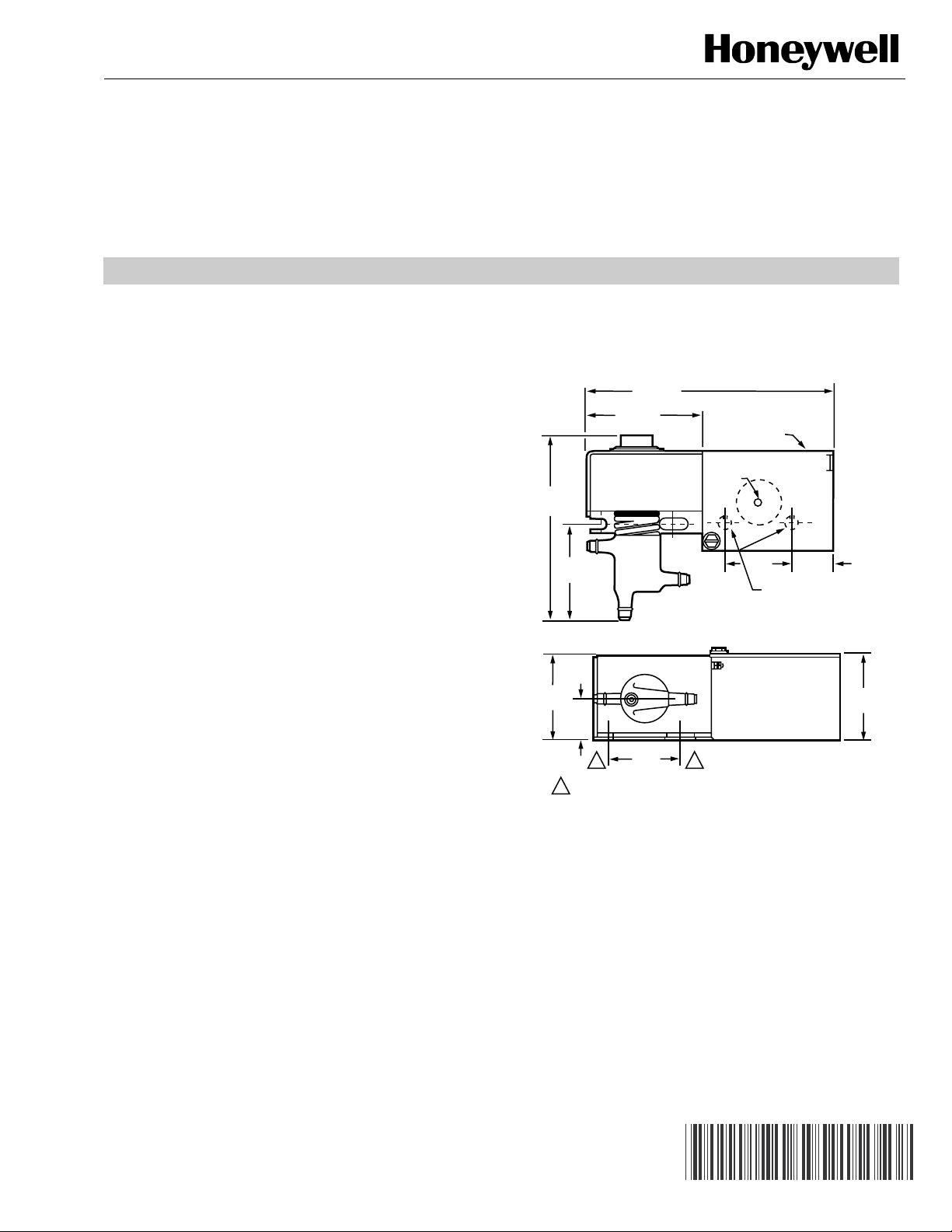
1. Position the relay on the duct or wall and mark the
knockout mounting holes or mark the first hole and
measure 1 in. (25mm) to the second hole. See Fig. 1.
2. Drill holes for no. 8 mounting screws obtained locally.
NOTE: When wall mounting, use the mounting holes on the
sides of the relay valve body or the knockout mounting holes on the inside of the splice box. See Fig. 2.
NOTE: The RP418 and RP818 are functional replacements
for the RP417 and RP817. Note the difference in
location of ports 1 and 2.
3-3/4 (96)
RP418A,C AND RP818A
1-5/8 (42)
RP418B; RP818B
2-3/4
(71)
1-1/4
(32)
1-1/4
(32)
7/16
(15)
1 (25)
1
1
MOUNTING CENTERS FOR NO. 8 SCREWS. MOUNTING CENTERS
MAY BE UP TO 1-5/16 (35) APART TO EASE INSTALLATION.
1
7/8 DIAMETER
KNOCKOUTS (2)
FOR 1/2 INCH
CONDUIT
GROUNDING
SCREW
1 (25)
5/8 (16)
KNOCKOUTS FOR
NO. 8 SCREWS
1-3/8
(35)
M18376
Fig. 1. RP418 and RP818 dimensions in in. (mm).
3. Attach the relay to the panel using mounting screws
obtain locally.
Panel Mounting
1. Line up the no. 8 mounting holes on the sides of the
valve body with existing holes in the panel or drill new
holes 1 in. (25 mm) apart.
2. Attach the relay to the panel using mounting screws
obtained locally.
® U.S. Registered Trademark
Copyright © 2002 Honeywell • All Rights Reserved
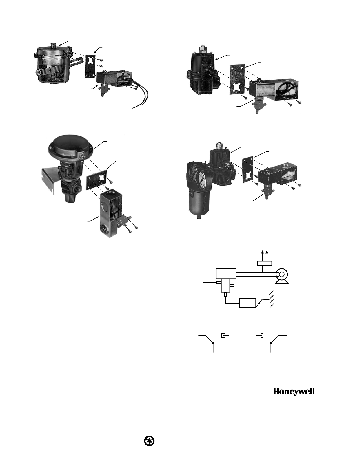
Device Mounting
The RP418 and RP818 Relays can be mounted directly to
MP516 operators, VP519C valves, or PP901B and PP902B
pressure regulators. A mounting bracket is available in
adaptor kit 14003638-001. This bracket must be used when
mounting the relay in this manner.
1. Use the mounting holes beneath the cover of the splice
box and attach the relay using mounting screws
obtained locally. See Fig. 2 through 5.
95-6046EF
Page 2
RP418A, B, C AND RP818A, B ELECTRIC/PNEUMATIC RELAYS
Printed in U.S.A. on recycled
paper containing at least 10%
post-consumer paper fibers.
MP516A
BRACKET
RP418 OR RP818
PP910B
BRACKET
M18372
Fig. 2. RP418 or RP818 relays mounted directly to an
MP516A operator using the 14003638-001 adaptor kit.
VP519C
BRACKET
RP418 OR RP818
M18373
Fig. 3. RP418 or RP818 relays mounted directly to a
VP512C valve using the 14003638-001 adaptor kit.
Wiring and Piping
All pneumatic piping connections on the RP418 and RP818
are sized for 1/4-in. (6mm) OD polyethylene tubing. The connections are sharp, barb-type connections. See Fig. 6 and 7.
Wiring connections on the RP418A and RP818A are made via
splices inside the splice box. Knockouts are provided on the
box. For ambient temperatures between 100 to 120°F (38 to
49°C) either use 75°C rated wire or attach a close-coupled
4 x 4 electrical box to the RP418A or RP818A splice box.
Make the wire splices within the electrical box.
Wire leads provide a means of connection on the RP418B
and RP818B. Use standard wire nut connectors, obtained
locally, when making these connections.
NOTE: A cord and plug are provided for wiring connections
on the RP418C.
The RP418 and RP818 relays require no adjustment or
calibration.
RP418 OR RP818
M18375
Fig. 4. RP418 or RP818 relays mounted directly to a
PP901B pressure regulator using the 14003638-001
adaptor kit.
PP920B
RP418 OR RP818
BRACKET
M18374
Fig. 5. RP418 or RP818 relays mounted directly to a PP902
pressure regulator using the 14003638-001 adaptor kit.
VOLTAGE
SUPPLY
FAN
SWITCH
RP418 OR
SUPPLY
AIR
1
RP818
2
EXHAUST
3
DAMPER
OPERATOR
FAN MOTOR
DAMPER
M18298
Fig. 6. RP418 and RP818 typical wiring and piping.
2
3
DEENERGIZED:
PORTS 2 AND
3 CONNECTED,
PORT 1 BLOCKED.
1
2
ENERGIZED:
PORTS 1 AND
3 CONNECTED,
PORT 2 BLOCKED.
3
1
M18299
Fig. 7. Pneumatic schematic.
Automation and Control Solutions
Honeywell Honeywell Limited-Honeywell Limitée
1985 Douglas Drive North 35 Dynamic Drive
Golden Valley, MN 55422 Scarborough, Ontario
M1V 4Z9
95-6046EF J.H. Rev. 1-02 customer.honeywell.com
Page 3

Relais électropneumatiques
RP418A, B et C et RP818A, B
AVANT D'INSTALLER CE PRODUIT
Les relais électropneumatiques RP418 et RP818 sont des
interrupteurs pneumatiques à commande électrique utilisés
comme dispositifs de blocage entre un système électrique et
un système de régulation pneumatique. Ils peuvent aussi être
utilisés comme relais d'arrêt, de purge, de répartition ou relais
sélecteurs.
Ces relais sont conçus pour être montés sur un mur ou sur un
panneau, selon le type d'application. Ils peuvent être installés
dans n'importe quelle position, sans que cela nuise à leur bon
fonctionnement.
NOTICE D’INSTALLATION
REMARQUE : Les relais RP418 et RP818 remplacent les
71
(2-3/4)
relais RP417 et RP817. Bien vérifier cependant où sont situés les orifices 1 et 2.
96 (3-3/4)
RP418A, C ET RP818A
42 (1-5/8)
RP418B; RP818B
OUVERTURES
D FON ABLES 7/8 DIAM. (2)
POUR CANALISATION
DE 1/2 PO
VIS MISE ¸
LA TERRE
La trousse de montage 14003638-001 offerte en option
permet de monter ces relais directement sur les servomoteurs
MP516A, les vannes VP519C ou les régulateurs de pression
PP901B et PP902B. Voir la section Montage sur appareils.
Les relais RP418 et RP818 s'installent sans outil spécial.
Consulter les dessins d'installation montrant l'endroit où
installer ces appareils.
INSTALLATION
Montage sur gaine ou montage mural
1. Placer le relais sur la gaine ou sur le mur et marquer les
trous des ouvertures défonçables ou marquer un premier trou et un deuxième trou, à 25 mm (1 po) du premier. Voir la Fig. 1.
2. Percer des trous pour des vis de montage n
fournies.
REMARQUE : Dans le cas d'un montage mural, utiliser les
trous de montage situés sur les côtés du corps
de la vanne du relais ou les ouvertures
défonçables à l'intérieur de la boîte de jonction.
Voir la Fig. 2.
3. Fixer le relais sur le panneau au moyen de vis de montage, non fournies.
Montage sur panneau
1. Aligner les trous pour des vis de montage no 8 de
chaque côté du corps de la vanne sur les trous déjà percés dans le panneau ou percer de nouveaux trous, à
25 mm (1 po) de distance l'un de l'autre.
2. Fixer le relais sur le panneau au moyen de vis de montage, non fournies.
o
8, non
32
(1-1/4)
32
(1-1/4)
15
(7/16)
25 (1)
1
1
LES CENTRES DES TROUS DE MONTAGE POUR VIS No 8
PEUVENT TRE DISTANTS DE 36 (1-6/18) DE MANIØRE ¸
FACILITER L’INSTALLATION.
1
25 (1)
16 (5/8)
OUVERTURES D FON ABLE
POUR VIS No 8
35
(1-3/8)
MF18376
Fig. 1. Encombrement des RP418 et RP818 en mm (po).
Montage sur appareils
Les relais RP418 et RP818 se montent directement sur les
servomoteurs MP516, les vannes VP519C ou les régulateurs
de pression PP901B et PP902B. La trousse de montage
14003638-001 offerte en option comprend un support de
montage nécessaire pour installer le relais sur un appareil.
1. Utiliser les trous de montage sous le couvercle de la
boîte de jonction; fixer le relais à l'aide de vis de montage, non fournies. Voir les Fig. 2 à 5.
® U.S. Registered Trademark
Copyright © 2002 Honeywell • All Rights Reserved
95-6046EF
Page 4

RELAIS ÉLECTROPNEUMATIQUES RP418A, B ET C ET RP818A, B
MP516A
SUPPORT
RP418 OU RP818
PP910B
SUPPORT
MF18372
Fig. 2. Relais RP418 ou RP818 montés directement
sur un servomoteur MP516A au moyen de
la trousse de montage 140003638-001.
VP519C
SUPPORT
RP418 OU RP818
MF18373
Fig. 3. Relais RP418 ou RP818 montés directement
sur une vanne VP512C au moyen de la trousse
de montage 140003638-001.
Raccordement électrique et pneumatique
Tous les raccords des canalisations pneumatiques sur le
RP418 et RP818 sont conçus pour des tuyaux en
polyéthylène de 6 mm (1/4 po) de diamètre extérieur. Ce sont
des raccords à crans. Voir les Fig. 6 et 7.
Les raccordements électriques du RP418A et RP818A sont
effectués par épissure dans la boîte de jonction. La boîte
comprend des ouvertures défonçables. Si la température
ambiante est de 38 à 49 °C (100 à 120 °F), utiliser un fil conçu
pour une température de 75 °C ou fixer une boîte électrique à
couplage direct de 4 x 4 sur la boîte de jonction du RP418A
ou RP818A.
RP418 OU RP818
MF18375
Fig. 4. Relais RP418 ou RP818 montés directement
sur le régulateur de pression PP901B au moyen
de la trousse de montage 14003638-001.
PP920B
RP418 OU RP818
SUPPORT
MF18374
Fig. 5. Relais RP418 ou RP818 montés directement
sur le régulateur de pression PP902 au moyen
de la trousse de montage 14003638-001.
TENSION
D'ALIMENTATION
INTERRUPTEUR
DU VENTILATEUR
SERVOMOTEUR
DU REGISTRE
MOTEUR DU
VENTILATEUR
REGISTRE
MF18298
AIR
D'ALIMENTATION
RP418 OU
RP818
1
3
2
ÉCHAPPEMENT
Fig. 6. Raccordement électrique et pneumatique type des
relais RP418 et RP818.
2
1
2
1
Des fils conducteurs permettent de raccorder le RP418AB ou
le RP818B. Utiliser des raccords de fils à écrou (non fournis)
avec ces conducteurs.
REMARQUE : Un cordon avec fiche est fourni pour le raccor-
dement du RP418C.
HORS TENSION : LES ORIFICES
2 ET 3 SONT RACCORDÉS;
L'ORIFICE 1 EST BLOQUÉ.
3
3
SOUS TENSION : LES ORIFICES
1 ET 3 SONT RACCORDÉS;
L'ORIFICE 2 EST BLOQUÉ.
MF18299
Fig. 7. Schéma de raccordement pneumatique.
Le RP418 et le RP818 ne nécessitent ni réglage ni
étalonnage.
Solutions de régulation et d’automatisation
Honeywell Honeywell Limited-Honeywell Limitée
1985 Douglas Drive North 35, Dynamic Drive
Golden Valley, MN 55422 Scarborough (Ontario)
95-6046EF J.H. Rév. 1-02 customer.honeywell.com
M1V 4Z9
Imprimé aux États-Unis sur du papier
recyclé contenant au moins 10 %
de fibres post-consommation.
 Loading...