

Page 1
ELECTRONIC/PNEUMATIC TRANSDUCER
c
APPLICATION
An E/P Transducer accepts a proportional voltage signal
from an electronic controller and converts it into a proportional pneumatic signal of 0.2 to 1.0 bar to operate
pneumatic actuators or reset pneumatic controllers.
The RP7517A accepts a 2...10 Vdc / 4...20 mA signal
directly from a MicroniK 100 output. The RP7517B includes
a voltage-to-current converter for use with an Excel DDC
output and Delta CPA. It may also be used in applications
where more than one transducer must be connected to one
MicroniK 100 output. The RP7517B requires an external
24 Vac power supply.
All E/P-Transducers supplied with 1 m cable
MAINTENANCE
A full range of maintenance programs is available from your
local registered Honeywell office.
RP7517A/B
PRODUCT DATA
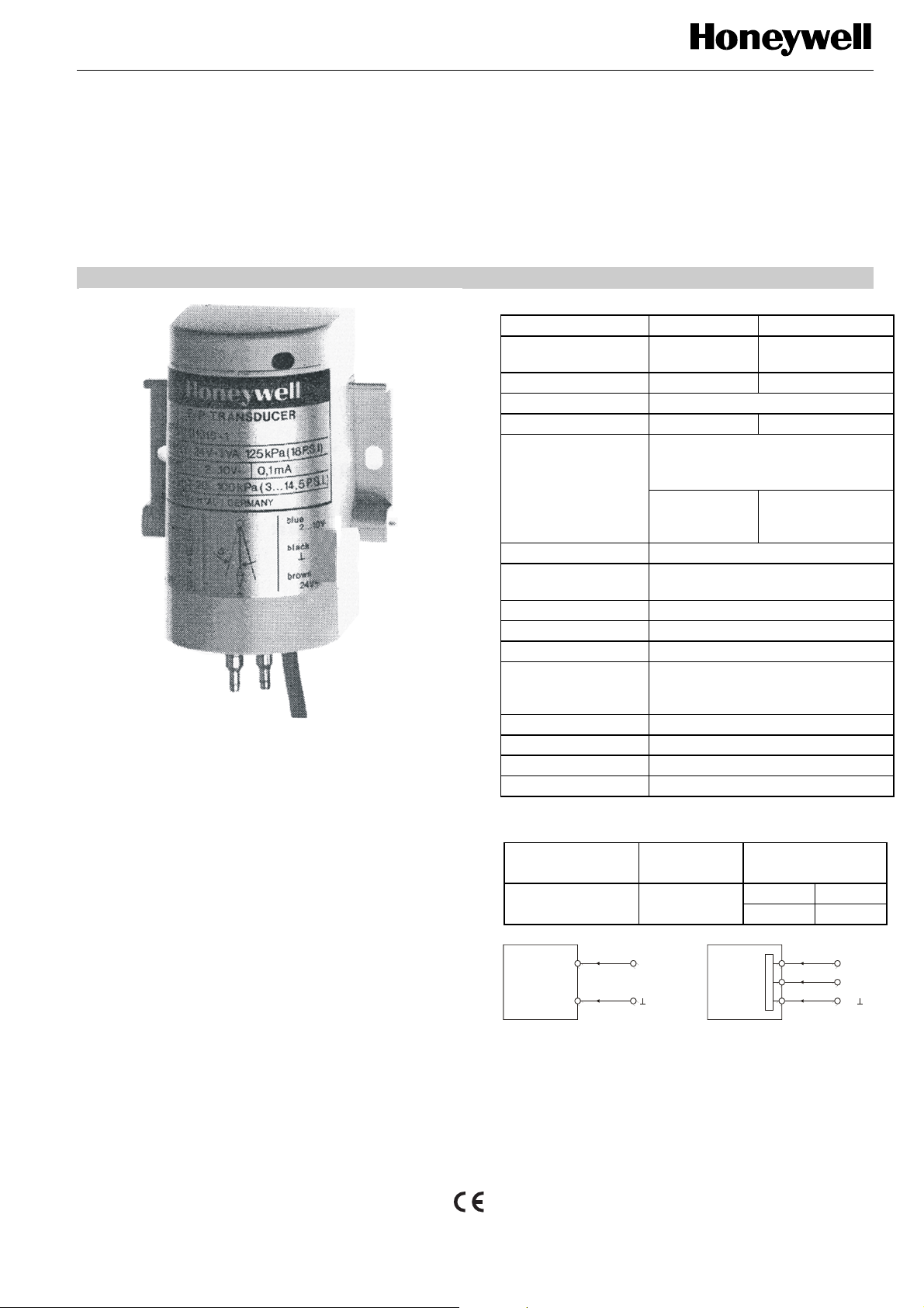
SPECIFICATIONS
Type No. RP7517A RP7517B
Power supply none
Power consumption 0.15 W 1.7 VA
Input signal 2...10 V
Min. current at 10 Vdc (15 mA) (0.1 mA)
0.2...1.0 bar (20...100 kPa) at
Output pressure at
1.25 bar (125 kPa)
main pressure
max. 0.035 bar (3.5 kPa) at 0 Vdc
min. 1.06 bar
(106 kPa) at
11.5 Vdc
Main air pressure 1.25 bar (125 kPa)
Main air pressure
independence
1% per 0.1 bar main air pressure
Maximum safe air 2.0 bar (200 kPa)
Air consumption 42 NL/h (700 sccm) at 0.6 bar
Air capacity 720 NL/h (12000 sccm)
Dual-barb-fittings for either 6 x 1 mm
Air connections
(1/4“ O.D.) or 4 x 0.75 mm (5/32“
O.D.) polyethylene tubing.
Calibration Factory calibrated
Ambient temperature 5...55ºC
Storage -30...+70ºC
Humidity 5...95% RH
WIRING
distance from E/PTransducer to
controller or
Delta CPA output
BLUE
RP7517A
BLACK
Fig. 1. Wiring and connections
NOTE: The E/P Transducer connection wire 24 V ⊥
(black) must be connected to the same potential
0 V level as the controller or Delta DGP.
type of wire max. length
local standard
Y = 2...10 Vdc
2...10 Vdc
100 m 150 m
1.0 mm2 1.5 mm2
RP7517B
+10% / -15%
24 V, 50/60Hz
min 1.12 bar
(112 kPa) at
11.5 Vdc
BLUE
c
o
n
v
BROWN
e
r
t
BLACK
e
r
Y = 2...10 Vd
24 V~
24 V
® U.S. Registered Trademark EN0B-0635GE51 R0908
Copyright © 2008 Honeywell Inc. • All rights reserved
Page 2
RP7517A/B ELECTRONIC/PNEUMATIC-TRANSDUCER
OPERATION
The basic operation is similar for both E/P-Transducers:
The input signal 2...10 V is fed directly to a coil on the
RP7517A or into a voltage to current converter in the
RP7517B.
The current through the coil produces a magnetic force on
the flapper. This force is balanced by the feedback force
developed by the nozzles pressure on the opposite side of
the flapper.
When the magnetic force on the flapper changes due to a
change in current, the position of the flapper over the
nozzle changes, and a new pressure is established. This
pressure is used to pilot the pneumatic amplifier, which
converts the low capacity pilot pressure to a high capacity
branch line. The operation span is fixed and the start-point
of the output signal is factory calibrated.
Both transducers are compensated to eliminate ambient
temperature influence. The transducers are protected by a
rigid plastic cover.
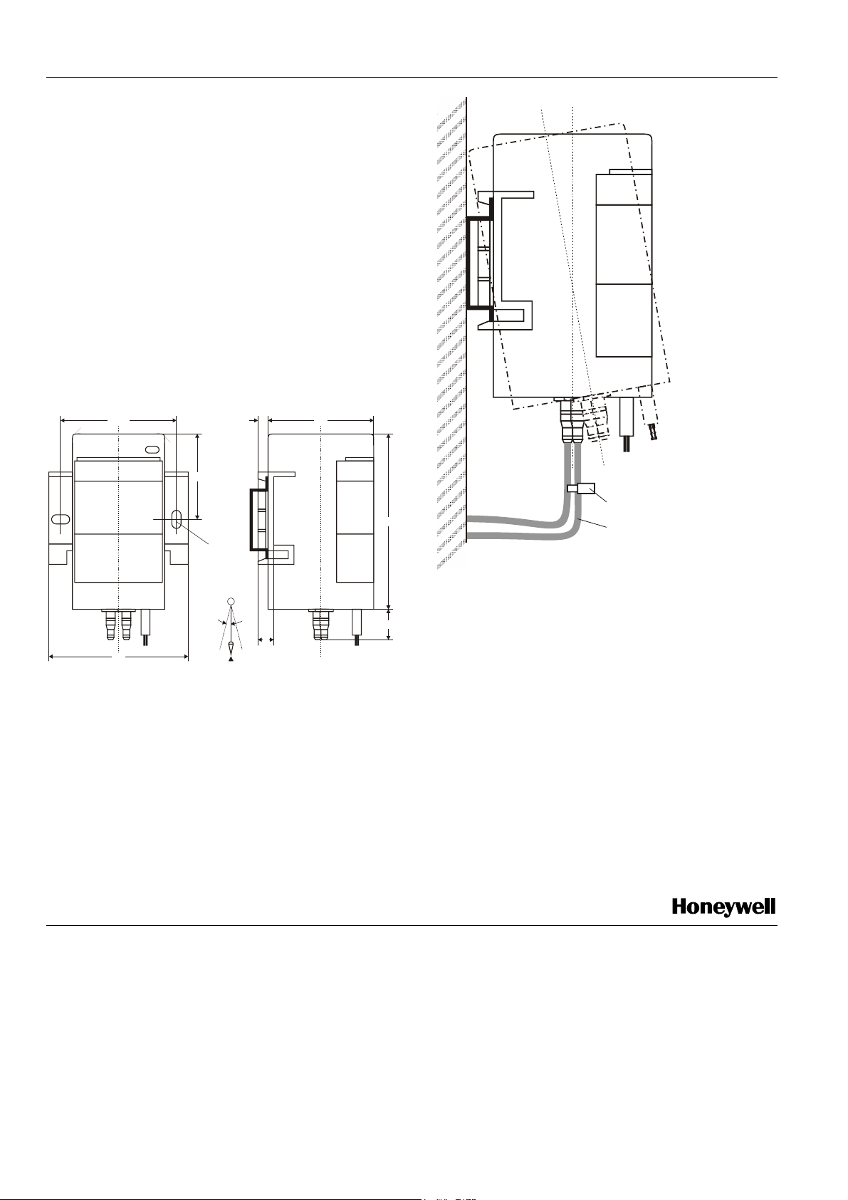
4.5
4751.5
38
diamet er
4.1
5°
7
62
Fig. 2. RP7517A/B dimensions (in mm)
MOUNTING
Wall mounting with two screws 4 mm diameter (see Fig. 2).
Rail mounting using the European Standard Rail 35 x 7.5
(EN 50022) (see Fig. 3).
Mount the transducer in the vertical position ONLY with a
maximum of 5 angular degree tolerance to the
perpendicular line (see Fig. 2).
78
13.5
1. For test or indication gauge
2. Additional length to dismount
from rail
Fig. 3. Mounting
START-UP INSTRUCTIONS
Before starting up the system, the following checks should
be made on the transducer:
1. Check that main line pressure is available and input
voltage is at maximum i.e. 12 Vdc.
2. Check that output pressure is at minimum, i.e.
112 kPa (1.12 bar) (RP7517A) or 120 kPa (1.2 bar)
(RP7517B).
3a. If the output pressure is within the transducer rating,
the system can be started up.
3b. If not, short out the contact pins with a screwdriver.
When this is done, the sound of discharging air should
be heard.
4. Check for correct output pressure build-up and repeat
step 3(b) if transducer does not function correctly.
Manufactured for and on behalf of the Environmental and Combustion Controls Division of Honeywell Technologies Sàrl, Ecublens, Route du Bois 37, Switzerland by its Authorized Representative:
Automation and Control Solutions
Honeywell GmbH
Böblinger Strasse 17
71101 Schönaich / Germany
Phone: (49) 7031 63701
Fax: (49) 7031 637493
http://ecc.emea.honeywell.com
Subject to change without notice. Printed in Germany
EN0B-0635GE51 R0908
 Loading...