

Honeywell ROME-B, ROME Product Installation Document
ROME Series
Relay Option Module Enclosure
Product Installation Document
PN 53530:B 9/14/2009 09-327
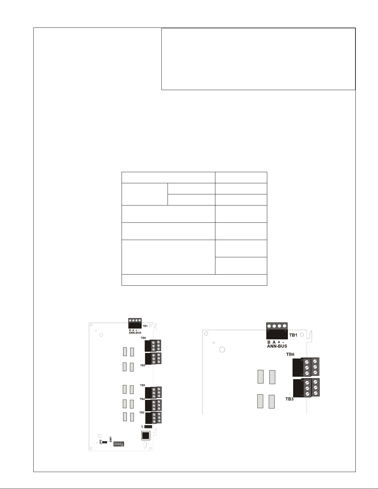
The ROME (Relay Option Module Enclosure, red) and ROME-B (black) is shipped with one ANN-BUS Relay Module
already installed. The ROME Series provides mounting space for one additional Relay Module or one addressable MultiModule.
Relay Module
The Relay Module provides 10 programmable Form-C relays when used with a compatible FACP (Fire Alarm Control
Panel). This document is provided as a quick reference. For more detailed programming information, refer to the appropriate FACP installation manual.
Relay Module Specifications
Operating Voltage 24 VDC
Max. Current @
24 VDC
Operating Temperature
Max. Wiring Distance from FACP
(with 12 AWG wire)
Relay Contact Ratings
Indoor Use in Dry Location Only
Alarm 75 mA
Standby 15 mA
32° to 120° F
(0° to 49° C)
1,250 ft. (380 m)
2 amps @ 30 VDC
(resistive)
0.5 amps @ 30 VAC
(resistive)
Relay Designations and Terminals
The relay numbers and terminal designations are illustrated in the following illustration.
R9 R10
R7 R8
NO
NC
C
Relay Module
R5 R6
R3 R4
R1 R2
NO
NC
C
Relay Module
Normally Open,
Normally Closed
and Common
terminals for each
relay follow the
same pattern as
illustrated above.
Wiring the Relay Module to an FACP
Refer to the following table and illustration for wiring connections.
1. All connections/sources are to be power-limited and
supervised.
2. 12 - 18 AWG (0.75 - 3.25 mm
2
) wire for 24 VDC circuit is
acceptable. Refer to the appropriate FACP manual.
3. Power wire distance limitation is set by 1.2 volt maximum line
drop from source to end of circuit.
4. Maximum distance from FACP to last ANN-BUS device must
not exceed 1,250 feet (380 m). Refer to Wiring Distance
Table in appropriate FACP manual for wire gauge and
distance limitations.
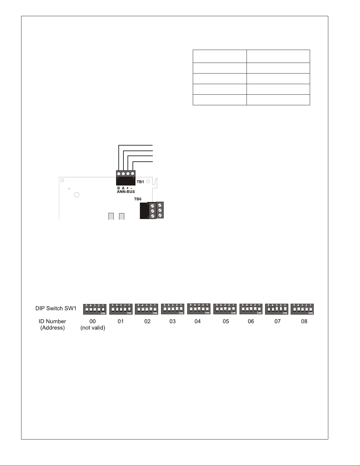
B (ANN-BUS)
A (ANN-BUS)
+ (24 VDC)
- (GND)
}Connect to FACP ANN-BUS and/or next device
}Connect to FACP or next device
Relay Terminals (TB1) FACP ANN-BUS Terminals
Terminal 1 (B) B (ANN-BUS)
Terminal 2 (A) A (ANN-BUS)
Terminal 3 (+) (+)
Terminal 4 (-) (-)
Relay Module
Setting Relay Module DIP Switches
Each ANN-BUS device requires a unique address. Relay Module DIP switch SW1 is used to set the address for the module. A maximum of 8 devices can be connected to the FACP ANN-BUS communication circuit. ANN-BUS device
addresses do not need to be sequential and can be set to any number between 01 and 08. Note that 00 is not a valid
address. The following illustrates the DIP switch settings for each address (ID Number):
2 ROME Series Installation Document — P/N 53530:B 9/14/2009
 Loading...