

Page 1

SmartLine RMA801
HART/DE Remote Indicator
User's Guide
34-ST-25-62
Revision 5.0
April 2020
Honeywell Process Solutions
Page 2

Page 3

Copyyrights, Notices a nd Trademarks
© Copyright 2020 by Honeywell, Inc.
Revision 5, April 2020
While this information is presented in good faith and believed to be accurate, Honeywell disclaims the implied
warranties of merchantability and fitness for a particular purpose and ma kes no express warranties except as may
be stated in its written agreement with and for its customers.
In no event is Honeywell liable to anyone for any indirect, special or consequential damages. The information and
specifications in this document are subject to change without notice.
Honeywell, PlantScape, Experion PKS, and TotalPlant are registered trademarks of Honeywell International Inc.
Other brand or product names are trademarks of their respective owners.
Honeywell Process Solutions
1250 W Sam Houston Pkwy S
Houston, TX 77042
Revision 5 RMA801 Remote Indicator User’s manual ii
Page 4
United States and
1-800-343-0228 Customer Service
hfs-tac-support@honeywell.com
http://bit.ly/2N5Vldi
About This Document
This guide provides the details of Honeywell RMA801 Remote Indicator for applications involving DE
and/or analog (4-20 mA) protocol.
Release Information
Document Name
RMA801 Remote Indicator User's Guide
First Release 1 February 2019
Approval updates 2 March 2019
R200 (incl. Flow and Level units) 3 June 2019
ATEX, IECEx and Control Drawing updates 4 September 2019
Document ID
#34-ST-25-62
Release
Number
Publication Date
Pipe bracket drawings updated.
SAEx, CCoE/PESO approvals added.
5 April 2020
Support and Contact Information
For Europe, Asia Pacific, North and South America contact details, see back page or refer to the
appropriate Honeywell Solution Support web site:
Honeywell Corporate www.honeywellprocess.com
Honeywell Process Solutions https://www.honeywellprocess.com/remote-meter-assemblies
Training Classes www.honeywellprocess.com/en-US/training
Telephone and Email Contacts
Area Organization Phone Number
Canada
Honeywell Inc.
1-800-423-9883 Global Technical Support
Global Email
Support
Field Product Sales
Revision 5 RMA801 Remote Indicator User’s manual iii
Honeywell Process
Solutions
Honeywell Process
Solutions
EMEA and Asia Pacific + 80012026455 or
+44 1202645583
Knowledge Base search engine
FP-Sales-Apps@Honeywell.com
Page 5
Symbol Definitions
The following table lists those symbols used in this document to denote certain conditions.
Symbol Definition
ATTENTION: Identifies information that requires special
consideration.
TIP: Identifies advice or hints for the user, often in terms of
performing a task.
REFERENCE -EXTERNAL: Identifies an additional source of
information outside of the bookset.
REFERENCE - INTERNAL: Identifies an additional source of
information within the bookset .
CAUTION
Indicates a situation which, if not avoided, may result in equipment
or work (data) on the system being damaged or lost, or may result in
the inability to properly operate the process.
CAUTION: Indicates a potentially hazardous situation which, if not
avoided, may result in minor or moderate injury. It may also be used
to alert against unsafe prac tices.
CAUTION symbol on the equipment refers the user to the product
manual for additional information. The symbol appears next to
required information in the manual.
WARNING: Indicates a potentially hazardous situation, which, if not
avoided, could result in serious injury or death.
WARNING symbol on the equipment refers the user to the product
manual for additional information. The symbol appears next to
required information in the manual.
WARNING, Risk of electrical shock: Potential shock hazard where
HAZARDOUS LIVE voltages greater than 30 Vrms, 42.4 Vpeak, or
60 VDC may be accessible.
ESD HAZARD: Danger of an electro-static discharge to which
equipment may be sensitive. Observe precautions for handling
electrostatic sensitive device s.
Protective Earth (PE) terminal: Provided for connection of the
protective earth (green or green/yellow) supply system conductor.
Functional earth terminal: Used for non-safety purposes such as
noise immunity improvement. NOTE: This connection shall be
iv RMA801 Remote Indicator User’s manual Revision 5
bonded to Protective Earth at the source of supply in accordance
with national local electrical code requirements.
Page 6
Symbol Definition
Earth Ground: Functional earth connection. NOTE: This
connection shall be bonded to Protective Earth at the source of
supply in accordance with national and local electr i cal co de
requirements.
Chassis Ground: Identifies a connection to the chassis or frame of
the equipment shall be bonded to Protective Earth at the source of
supply in accordance with national and local electr i cal co de
requirements.
Revision 5 RMA801 Remote Indicator User’s manual v
Page 7

Terms and Acronyms
Term Definition
AWG
DMM
DE
Device A physical entity capable of performing one or more specific functions. Examples
EEPROM Electrically Erasable Programmable Read Only Memory
EMI Electromagnetic Interfer en ce
Event An instantaneous occurrence that is significant to scheduling block execution and
Field Device A fieldbus-compatible device that contains and executes function blocks.
HART Highway Addressable Remote Transmitter
Hz Hertz
IDE Integrated Development Environment
inH2O Inches of Water
LRL Lower range Limit
LRV Lower Range Value
MCT Multi Communication Toolkit
American Wire Gauge
Digital Multimeter
Digital Enhanced Communications Mode
include Remote Indicators, actuators, controllers, operator interfaces.
to the operational (event) view of the application.
mmHg Millimeters of Mercury
mV Millivolts
NVM Non-Volatile Memory
PSI Pounds per Square Inch
PV Process Variable
PWA Printed Wiring Assembly
RFI Radio Frequency Interference
RMA Remote Meter Assembly (refered to as a Remote Indicator)
SAT Smartline anytime Tool to upgrade the firmware
SCT SmartLine Configuration Tool
URL Upper Range Limit
URV Upper Range Value
VCC An electronics designation that refers to voltage from a power supply connected to
the "collector" terminal of a bipolar transistor.
Vdc Volts Direct Current
vi RMA801 Remote Indicator User’s manual Revision 5
Page 8

Contents
COPYYRIGHTS, NOTICES AND TRADEMARKS ................................. II
INTRODUCTION 1
1.1 About the RMA801 Remote Indicator ...................................................................................... 1
1.2 Features and Options ............................................................................................................... 1
1.3 RMA801 major assembly and electronic housing components ........................................... 2
1.4 Dimensions ................................................................................................................................ 4
1.5 RMA801 Remote Indicator Nameplate .................................................................................... 5
1.6 Safety Certification Information ............................................................................................... 5
1.7 Display Options – Standard Display ....................................................................................... 6
1.8 Two Integrated-Button Assembly (Standard Display) ........................................................... 7
INSTAL LATION AND STARTUP ........................................................................ 8
2.1 Installation Site Evaluation ...................................................................................................... 8
2.2 Display Installation Precautions .............................................................................................. 8
2.3 Mounting Remote Indicator ...................................................................................................... 9
2.3.1 Mounting Dimensions ......................................................................................................................... 9
2.3.2 Bracket Mounting Procedure .............................................................................................................. 9
2.4 Wiring a Remote Indicator ...................................................................................................... 12
2.4.1 Overview........................................................................................................................................... 12
2.4.2 Terminal Block .................................................................................................................................. 12
2.4.3 Wiring Procedure .............................................................................................................................. 15
2.4.4 Supply Voltage Limiting Requirements ............................................................................................. 15
PERFORMANCE SPECIFICATIONS ............................................................... 16
OPERATION 17
4.1 Overview 17
4.2 Configuration using SCT or MCT Toolkit for DE Models 17
4.3 Configuration using Standard Display 18
4.3.1 Menu Navigation 19
4.3.2 Data Entry 19
4.3.3 Editing a Numeric Val ue 20
4.3.4 Selecting a new setting from a list of choices 20
4.3.5 The Standard Display Menu 20
4.3.6 Standard Display Abbreviations: 26
4.4 Changing the Write protect Direction 27
4.5 Monitoring the Standard Display 29
Revision 5 RMA801 Remote Indicator User’s manual vii
Page 9

MAINTENANCE ............................................................................................... 32
5.1 Overview ................................................................................................................................. 32
5.2 Preventive Maintenance Practices and Schedules ............................................................ 32
5.3 Replacing the Local Display and Communication Electronic Assembly ........................ 32
5.4 Upgrading the firmware ........................................................................................................ 35
CALIBRATION ................................................................................................. 36
6.1 Remote Indicator calibration when connected in loop with HART transmitter............... 36
6.2 Remote Indicator calibration when connected in loop with DE tansmitter ..................... 37
TROUBLESHOOTING ..................................................................................... 38
7.1 Overview ................................................................................................................................. 38
7.2 Critical Diagnostics Screens ................................................................................................ 38
7.2.1 Fault Conditions and recommended Correcti ve Actions ................................................................. 39
7.3 Important Notes ..................................................................................................................... 39
SECURITY ....................................................................................................... 40
8.1 Security guidelines ................................................................................................................ 40
SPARE PARTS LIST ....................................................................................... 41
9.1 Overview ................................................................................................................................. 41
CERTIFICATIONS AND APPROVALS ........................................................... 43
10.1 European Directive Information (CE Mark) ..................................................................... 43
INDEX .............................................................................................................. 50
viii RMA801 Remote Indicator User’s manual Revision 5
Page 10

Tables
Table 1: Feature and Options ................................................................................................... 1
Table 2: Transmitter Models Supported ................................................................................... 2
Table 3: Display Characteristics ............................................................................................... 6
Table 4: Two-Button Functions .............................................................................................. 18
Table 5: Two-Button Data Entry ............................................................................................. 19
Table 6: RMA801: Standard Display Menu ............................................................................ 21
Table 7: The Standard Display abbreviations ......................................................................... 26
Table 8: Write Protect Jumpers .............................................................................................. 28
Table 9: Standard Display with PV Format Display Indications .............................................. 29
Table 10: Fault Conditions and Recommended Corrective Actions. ....................................... 39
Table 11: Summary List of Recommended Spare Parts ......................................................... 41
Table 12: Pipe and Wall Bracket Parts (Refer to Figure 19) ................................................... 41
Table 13: Remote Indicator Major Assemblies ....................................................................... 42
Figures
Figure 1: RMA801 Electronic Housing 2
Figure 2: Electronic Housing components 3
Figure 3: Dimensions of Remote Indicator 4
Figure 4 –Typical RMA801 Nameplate 5
Figure 5: Typical Pipe Mounted Installations 9
Figure 6: Mounting Bracket Secured to a Remote indicator 10
Figure 7: Pipe Mounting Bracket Secured to a Horizontal or Vertical Pipe 11
Figure 8: Remote Indicator Secured to a Wall Mounting Bracket 11
Figure 9: Remote Indicator connected on the negative side of loop (analog mode) 12
Figure 10: Remote Indicator connected on the positive side of loop (analog mode) 13
Figure 11: Remote Indicator connected on the negative side of loop (DE mode) 13
Figure 12: DE/ANALOG Terminal Block 14
Figure 13: RMA801 Terminal Block 14
Figure 14: RMA HANDHELD WIRING – DE MODE (An a log /Digital) 17
Figure 15: Two-Button Option 18
Figure 16: Locating Simulation and Write Protect Jumpers 27
Figure 17: Module Replacement 33
Figure 18: Local Display Fault Diagnostic Conditions 38
Figure 19: Pipe and Wall Bracket Parts 41
Figure 20: Electronic Housing, Terminal Block End 42
Revision 5 RMA801 Remote Indicator User’s manual ix
Page 11

Page 12
Communication Protoco ls
Analog (4-20 mA), Honeywell DE (Refer Table 2 for supported
devices)
PV Display
• Display mA or percent value for any analog (4-20 mA)
Device Configuration
• Manual - using display buttons
devices)
Human-Machine Interface
Standard Display:
• Two-mode operations: PV displ a y and Menu Na vigat ion
Display language: English only
Device Diagnostics
Approvals
ATEX, CSA, FM, IECx. Refer to Appendix A for details.
Mounting Brackets
Pipe mounting and wall mounting brackets in carbon steel and 316
stainless steel.
Firmware Upgrade
SAT tool for firmware upgrade
Introduction
1.1 About t he RMA801 Remote Indicator
The RMA801 Remote Indicator provides a means of remote-mounting a meter (display) that is
associated with a Honeywell Smartline Transmitter or any transmitter operating in a 4-20 mA current
loop.
The RMA801 is a DE/Analog Remote Indicator which can be connected anywhere along the current
loop, providing easy access to data from devices that are mounted in inaccessible locations.
For analog PV, the RMA801 measures the loop current and displays the equivalent PV value on the
display.
The RMA801 will autoconfigure when connected to Honeywell - DE transmitters when a database
upload is performed (Refer Table 2
The RMA801 - Remote Indicator can be used in hazardous environments or in ordinary
environments. When used in hazardous environments, the remote housing must be configured as per
local installation codes.
The display module fitting allows for rotation in 90 degree increments, allowing the RMA801 to be
mounted in various orientations.
for supported devices).
1.2 Features and Options
Table 1: Feature and Options
Feature/Option Standard/Available Options
transmitters
• Temperature, Pressure, Flow and Level units support.
• Autoconfiguration for DE devices (Refer Table 2 for supported
(HMI)
• 0, 90, 180 & 270 degree viewing position adjustments
Revision 5 RMA801 Remote Indicator User’s manual 1
Page 13
Models
STT700
Temperature
Yes
Yes
STT250
Temperature
Yes
Yes
STT850
Temperature
Yes
Yes
STT750
Temperature
NA
Yes
ST 800
Pressure
Yes
Yes
ST 700
Pressure
Yes
Yes
ST3000
Pressure
Yes
Yes
STT3000
Temperature
Yes
Yes
SLG700
Level
NA
Yes
SMV3000
Variable
Transmitter
Table 2: Transmitter Models Supported
Type DE protocol Analog (4-20mA)
SMV800,
Multi
No Yes
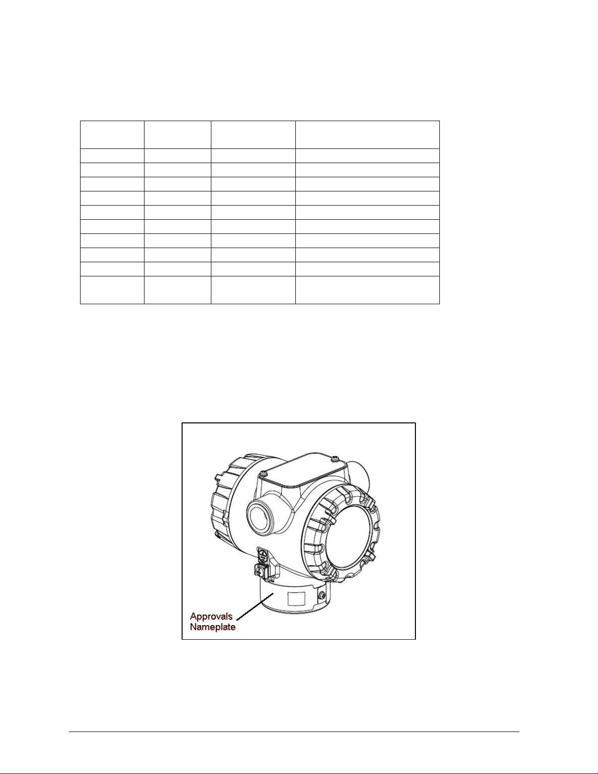
1.3 RMA801 major assembly and electronic housing components
The following illustrations depict the electronic housing components.
Figure 1: RMA801 Electronic Housing
2 RMA801 Remote Indicator User’s manual Revision 5
Page 14
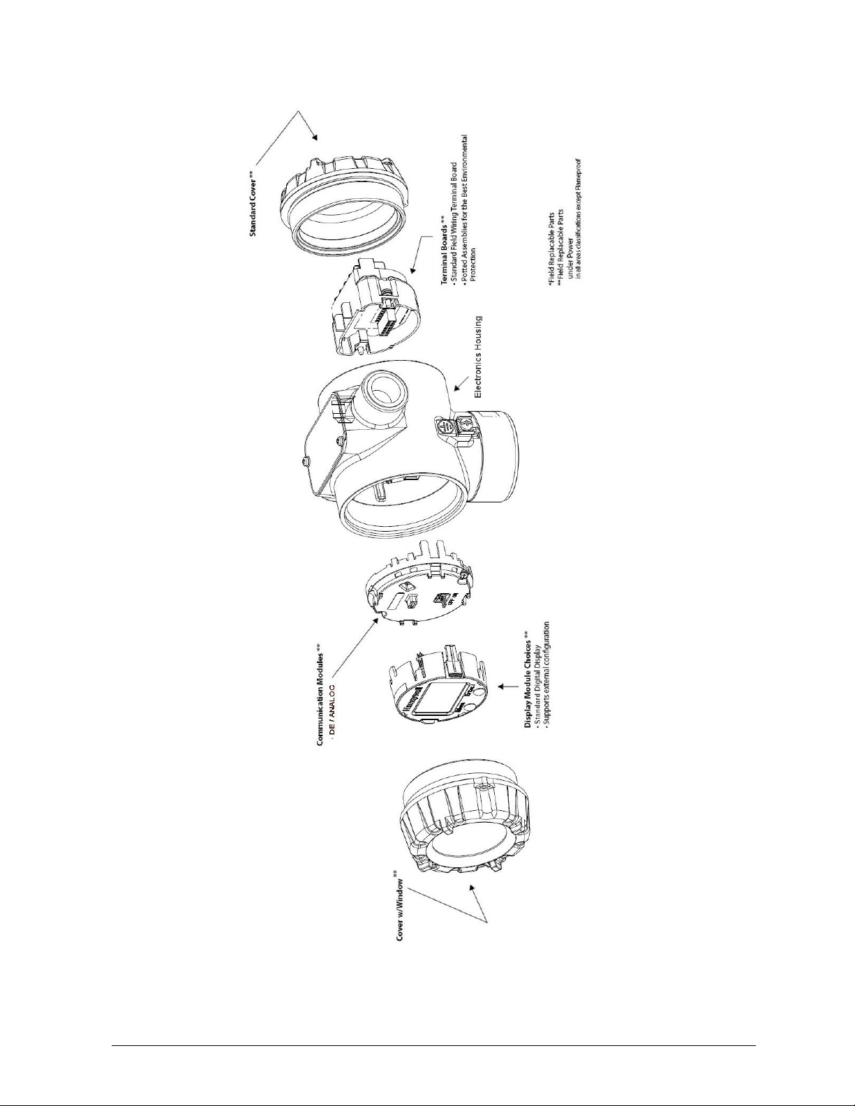
Figure 2: Electronic Housing components
Revision 5 RMA801 Remote Indicator User’s manual 3
Page 15
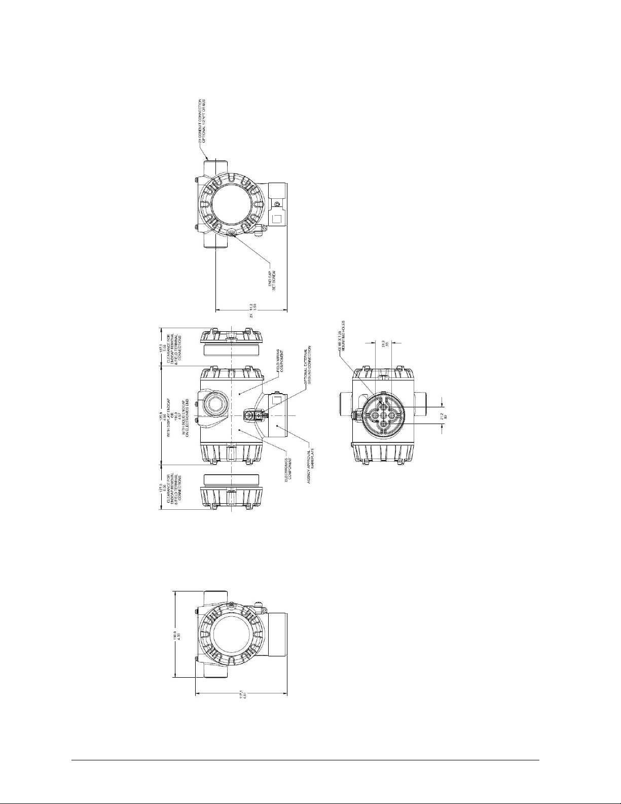
1.4 Dimensions
Figure 3: Dimensions of Remote Indicator
4 RMA801 Remote Indicator User’s manual Revision 5
Page 16
1.5 RMA801 Remote Indicator Nameplate
The Remote Indicator nameplate mounted on the bottom of the electronics housing (see Figure 1,
“approvals” nameplate) lists model number, physical configuration, electronics options, accessories,
certifications, and manufacturing specialties.
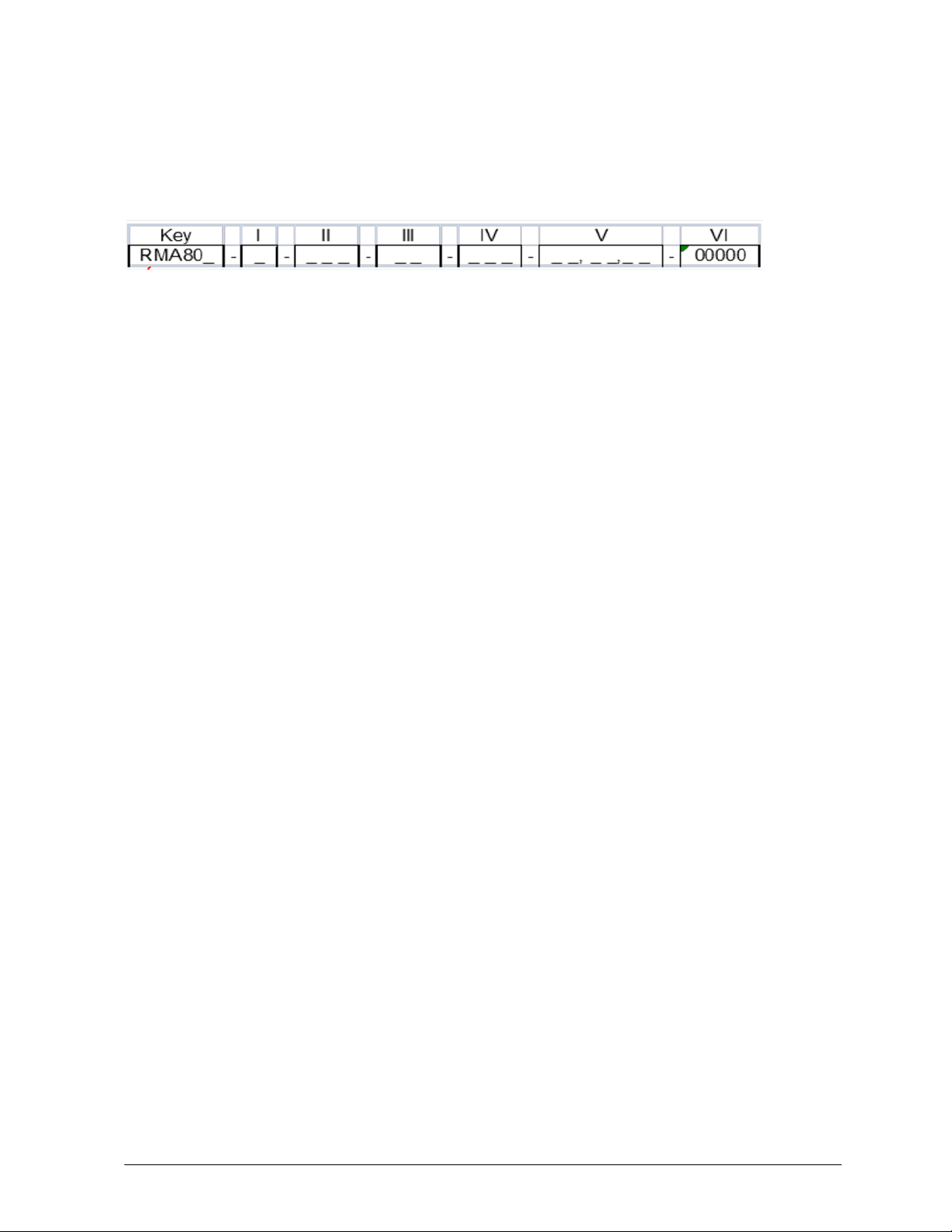
Figure 4 –Typical RMA801 Nameplate
Identification of the series and basic Remote Indicator type is captured in the last digit in the key
number. The last digit represent s itype.
• A value of 1 in the last d ig it m e ans the Remote Indicator type is RMA801 DE/Analog
For a complete selection breakdown of model number, refer to the appropriate specification and Model
Selection Guide provided as separate documents. (Modele selection guide #34-ST-16-90)
1.6 Safety Certification Information
An “approvals” nameplate is located on the bottom of the electronics housing; see Figure 1 for the exact
location. The approvals nameplate contains information and service marks that disclose the Remote
Indicator compliance inform ation. Refer to Appendix A of this document for safety certification
requirements and details.
Revision 5 RMA801 Remote Indicator User’s manual 5
Page 17

• 360° rotation in 90° increments
1.7 Display Options – Standard Display
The RMA801 Remote Indicator includes Honeywell’s Standard Display option.
Table 3: Display Characteristics
Standard Display
• 2 lines, 16 characters
• Standard temperatue, pressure, flow and level engineering
units of measurement:
− Temperature: °C, °F, °R, K, mV, Ohm
− Pressure: inH2O@39ºF, mH2O@4ºC,
cmH2O@4ºC, Torr, mmH2O@68ºF, ftH2O@68ºF,
inH2O@68ºF, inH2O@60ºF, atm, Pa, kPa, MPa,
gf/cm2, kgf/cm2, psi, mbar, bar, inHg@0ºC,
mmHg@0ºC, mmH2O@4ºC.
− Flow: ft3/sec, gal/min, gal/hr, liter/min, liter/hr,
m3/sec, m3/hr, Pounds per sec(lbm/sec), Pounds per
min (lbm/min), Pounds per hr(lbm/hr), kg/sec, kg/hr,
Standard Cubic Feet per min (SFt3/m), Standard
Cubic Feet per hr (SFt3/h), Standard Cubic Feet per
Day (SFt3/d), Metric Standard Cubic Feet per
Hour(MSCFH), Normal Cubic meter per hr(NM3/h),
Million Standard Cubic Feet per Day (MMSCFD),
Million Standard Cubic Feet per Hour (MMSCFH)
− LEVEL: m, cm, mm, in, ft
• Diagnostic messages
• Supports 2-button for menu navigation
• Device configuration
• English language only
6 RMA801 Remote Indicator User’s manual Revision 5
Page 18
Lower range value (LRV): A display parameter (Standard display),
1.8 Two Integrated-Button Assembly (Standard Display)
The iIntegrated two-button assembly for the Standard Displ ay provides the following features and
capabilities:
• Menu and enter key functionality.
• With the menu-driven display:
o Comprehensive on-screen menu for navigation.
o RMA Configuration – Select PV, Select Unit, Enter LRV, Enter URV, Input
Calibration, Square root selection, Scale low, Scale high, TAG, BUNIT.
See Notes below
o RMA Calibration
o Display Configuration - Contrast
o RMA Diagnostics.
which allows users to enter the measuring value for which the analog
output will be scaled to 4mA.
Upper range value (URV): A display parameter (Standard display),
which allows users to enter the measuring value for which the analog
output will be scaled to 20mA
Notes:
1. User should configure LRV and URV when connected to analog transmitters. For DE
transmitters LRV and URV are auto-configured from device when upload database is
performed.
2. For flow configuration when connected to Analog pressure devices user has to enable SQRT
parameter and configure SCLLO & SCLHI
3. For flow configuration when connected to DE pressure devices SQRT parameter is enabled
automatically when SQRT is configured in HOST and upload database is performed. User need
to manually enter SCLLO & SCLHI values
Revision 5 RMA801 Remote Indicator User’s manual 7
Page 19

Installation and Startup
2.1 Installation Site Evaluation
Evaluate the site selected for the Remote Indicator installation with respect to the process system design
specifications and Honeywell’s published performance characteristics for your particular model. Some
parameters that you may want to include in your site evaluation are:
• Environmental Conditions:
o Ambient Temperature
o Relative Humidity
• Potential Noise Sources:
o Radio Frequency Interference (RFI)
o Electromagnetic Interference (EMI)
• Vibration Sources
o Motorized System Devices (e.g., pumps)
o Valve Cavitation
• Process Parameters
o Temperature
o Maximum Pressure Rating
2.2 Display Installation Precautions
Temperature extremes can affect display quality. The display can go blank if the temperature is below 20°C or above +70°C; however, this is only a temporary condition. The display will again be readable
when temperatures return to within operable limits.
8 RMA801 Remote Indicator User’s manual Revision 5
Page 20

2.3 Mounting Remote Indicator
Remote Indicator models can be attached to a two-inch (50.8 millimeter) vertical or horizontal pipe
using Honeywell’s optional pipe mounting bracket. The Remote Indicator can also be wall mounted
using Honeywell’s optional wall mounint bracket as shown in Figure 5.
2.3.1 Mounting Dimensions
Refer to Honeywell drawing number 51455045* for detailed electronic housing dimensions. Refer to
Honeywell drawing numbers 32306827
Detailed Pipe Angle mounting dimenisons and 32306828
Abbreviated overall dimensions are also shown on the Specification Sheets for the Remot e Indicator
models. Its assumed that the mounting dimensions have already been considered and the mounting area
can accommodate the Remote Indicator.
2.3.2 Bracket Mounting Procedure
1. Pipe Mount Option -Refer toFigures below. Align the two mounting holes at the bottom of the
Remote Indicator with the two slots in the mounting bracket and assemble the (2) M8 hex cap
screws, (2) lockwashers and (2) flat washers provided.
*
for detailed pipe mounting dimensions, 50124813* for
*
for detailed wall mounting dimensions.
2. Rotate the Remote Indicator assembly to the desired position and torque the M8 hex cap screws
to 27,0 Nm/20,0 Lb-ft maximum
* Honeywell drawings can be supplied on request.
Figure 5: Pipe Mount - Horizontal Mounting Bracket
Revision 5 RMA801 Remote Indicator User’s manual 9
Page 21

Figure 6: Pipe Mount - Vertical Mounting Bracket
Figure 7: Mounting Bracket Secured to a Remote indicator
10 RMA801 Remote Indicator User’s manual Revision 5
Page 22

3. Position the bracket on a 2-inch (50.8 mm) horizontal or vertical pipe, and install a “U” bolt
around the pipe and through the holes in the bracket. Secure the bracket with (2) M10 hex nuts,
(2) flat washers and (2) lock washers provided. Refer Figure 7.
Figure 8: Pipe Mounting Bracket Secured to a Horizontal or Vertical Pipe
4.
Wall Mount Option - Refer Figure 8 Position the bracket on the mounting surface at the desired
location and secure the bracket to the mounting surface using the appropriate hardware (Wall
mounting hardware requirements to be determined and supplied by the end user).
Figure 9: Remote Indicator Secured to a Wall Mounting Bracket
Revision 5 RMA801 Remote Indicator User’s manual 11
Page 23

Terminal No.
Description
5
Loop +ve
6
Loop -ve
9
DE COMM
2.4 Wiring a Remote Indicator
2.4.1 Overview
The Remote Indicator is designed to operate in normal 4-20mA analog mode with 4-20 mA /HART
enabled transmitters or DE mode for Honeywell SmartLine transmitters in digital and analog modes.
(Except SMV800/DE)
For improved noise performance, it is recommended to provide earth ground for both transmitter and
RMA housing.
2.4.2 Terminal Block
The RMA801 has 3 terminals. Following table provides the connection details-
Three screw terminals suitable for wirings up to (16AWG)
• Shielded, twisted-pair cable such as Belden 9318 or equivalent must be used for all
signal/power wiring.
• The cable shield must be connected at only one end of the cable. Connect it to the power supply
side and leave the shield insulated at the transmitter side and RMA side.
Note: If solid core wire is used strip insulation 1/4 in (6 mm). Once inserted under the square
washer the stripped portion should be contained under the square washer. If multi-stranded wire
is used, a ferrule is to be used and the stripped wire should be in the insulated portion of the
ferrule. The ferrule can be also be used on the solid core wire.
Loop Terminals 5 & 6 shall be connected in series with the 4-20 ma loop for both analog and DE
modes. Additionally, third wire (Terminal 9) is required for DE communication in DE mode only.
Loop wiring for analog and DE mode is shown in figure below.
Figure 10: Remote Indicator connected on the negative side of loop (analog mode)
12 RMA801 Remote Indicator User’s manual Revision 5
Page 24

Figure 11: Remote Indicator connected on the positive side of loop (analog mode)
Figure 12: Remote Indicator connected on the negative side of loop (DE mode)
Note – The resistor “R” indicates the loop resistor which is needed for HART and DE communication
and is typically provided by the user or cont ro l system .
ATTENTION
Wiring must comply with local codes, regulations and ordinances. Grounding
may be required to meet various approval body certifications, for example CE
conformity. Refer to Appendix A of this document for details.
Revision 5 RMA801 Remote Indicator User’s manual 13
Page 25

Figure 13: DE/ANALOG Terminal Block
Figure 14: RMA801 Terminal Block
14 RMA801 Remote Indicator User’s manual Revision 5
Page 26

2.4.3 Wiring Procedure
1.
See Figure 12, for parts locations. Loosen the end cap lock using a 1.5 mm Allen wrench.
2. Remove the end cap cover from the terminal block end of the electronics housing.
3. Feed loop power leads through one end of the conduit entrances on either side of the
electronics housing. The Remote Indicator accepts up to 16 AWG wire.
4. Plug the unused conduit entrance with a conduit plug appropriate for the environment.
5. Follow the attached wiring diagram for respective connections with transmitters. Torque
terminal screws to 0,6 N.m (5.3 lbf.in) to 0.8 N.m (7.0 lbf.in).
6. Connect the Loop Power wiring shield to earth ground only at the power supply side.
7. Replace the end cap and secure it in place being careful not to damage the wires.
ATTENTION
Ensure the RMA housing is properly earth grounded. It is
recommended to use 8AWG (or 8.37mm2) bare or green covered wire.
ATTENTION
The Remote Indicator is polarity-sensitive and has Reverse Polarity
Protection.
2.4.4 Supply Voltage Limiting Requirements
If the selected Remote Indicator complies with the ATEX 4 directive for self-declared approval per
94/9EC, the power supply must include a voltage-limiting device. Voltage must be limited such that it
does not exceed 30 V DC. Consult the process design system documentation.
Min. loop voltage = 2.3Vdc + MinVTx + (Rloop * I max /1000)
Loop Supply Voltage
Requirement
Display Performance
Where:
MinVTx is the transmitter minimum supply voltage
Rloop is the resistance on the loop (in ohms)
I max is High Fail Safe/Burnout current in mA
The LCD display will turn blank below -20 °C and above 70 °C
(-4°F and 158°F), rendering the display unreadable. However,
the loop will continue to function.
Revision 5 RMA801 Remote Indicator User’s manual 15
Page 27

Parameter
Deg. C Deg. F
Ambient Temperature
Reference
-23 +/-2 °C -73 +/- 2°F
Rated
-40 to 85 °C -40 to +185°F
Operative
-20 to 70 °C -4 to +158°F
Transportation/Storage
-50 to +100°C -58 to +212°F
Humidity (% RH)
Rack Mounting Field Housing
Reference
10 – 55% RH 10 – 55% R H
Rated
5 - 95% RH 5 – 100% RH
Operative
5 – 100% RH 5 – 100% RH
Transportation/Storage
5 – 100% RH 5 – 100% R H
Design Specifications
Input Signal
4-20 mA
Accuracy:
• DE
Honeywell Digital (DE) Mode
Reproduces the transmitter signal exactly to within its
resolution
Display
6 digits numeric indication
Display Resolution
0.01 unit for reading range (-9 99 t o 999)
999999).
Display Update Rate
2 seconds
Display Indicati on Ac cur acy
0.1% of calibrated span (+/-1 digit)
Maximum Meter Voltage
30V DC
Max Loop Voltage Drop
≤ 2.3V @ 21.5mA
Min Loop Operating Current
3.6mA
All calibration constants are stored in non-volatile memory
and are not affected by power loss.
Failure mode
LCD display failure will not affect transmitter operation
Reverse Polarity Protection
Yes
Min. loop voltage = 2.3Vdc + MinVTx + (Rloop * I max
I max is High Fail Safe/Burnout current in mA
The LCD display will turn blank below -20 °C and above
However, the loop will continue to function.
Performance Specifications
• Analog 4-20 mA Mode
• Temperature Effect
Power Fail
Loop Supply Voltage
Requirement
+/- 0.1% of Span @ 23 +/-2 °C (+/- 1 digit)
+/- 0.01 % of Span /°C (+/- 1 digit)
Same as transmitter*
0.1 unit for reading range (-9 999 to -1000) or (1000 unit to 9999).
1 unit for reading range (-99999 to -10000) or (10000 to 99999 ).
10 units for reading range (-999999 to -100000 ) or (100000 to
/1000)
Where:
MinVTx is the transmitter minimum supply voltage
Rloop is the resistance on the loop (in ohms)
Display Performanc e
*Reproduces the transmitter signal exactly to within its resolution
70 °C
(-4°F and 158°F), rendering the display unreadable.
16 RMA801 Remote Indicator User’s manual Revision 5
Page 28

Operation
4.1 Overview
This section provides the information and processes involved for Remote Indicator operation using DE
host and the 2-buttons on the front of the display.
4.2 Conf iguration using SCT or MCT Toolkit for DE Models
The SCT or MCT Toolkit can be connected across the loop terminals of transmitter. After power is
applied on the loop, perform the upload database in SCT/MCT Toolkit then RMA parameters will be
auto-configured. For every configuration change in the transmitter, it is recommended to perform the
database upload to reflect te changes in RMA801.
Figure 15: RMA HANDHELD WIRING – DE MODE (Analog/Digital)
NOTE:
Any configuration change made in DE device will require upload database operation from host to
configure the RMA. This is applicable for analog and digital mode.
CAUTION
Two hosts should not be connected to DE device. DE device
does not support dual master
Revision 5 RMA801 Remote Indicator User’s manual 17
Page 29

Physical
Button
Scroll to next menu item in an active
To return back to previous menu
Entry confirmation
4.3 Conf iguration using Standard Display
For analog/HART transmitter, match the RMA801 parameters to the connected transmitter parameters
using the Standard Display menu.
The Remote Indicator’s two-button interface provides a user interface and an ability to configure the
display parameters. The figure below shows the location of the two-button option and the labels for
each button.
Menu
Enter ↵
Figure 16: Two-Button Option
Table 4: Two-Button Functions
Action Description
Parameter
Selection and value
entry
list.
Scroll through alphanumeric
parameter value list and change to
the desired value.
Enter to Main Menu from Normal PV
display.
Call up a lower-level menu.
Select an item for data entry.
Confirm a data entry operation
.
18 RMA801 Remote Indicator User’s manual Revision 5
Page 30

Screen
Symbol
Display the low limit for this parameter.
This symbol only appears in the left-most position of the data entry field.
0 thru 9,
Decimal
4.3.1 Menu Navigation
The user must press ↵ button to call up the Main Menu. To exit the Main Menu and return to the PV
display screen, select <EXIT>.
Use the button to scroll through the list of menu items. Press the ↵ button to select an item for data
entry or activation. When an item is selected for data entry or activation, the cursor is positione d over
the left-most digit to allow editing of the value. No action is taken against a menu item until the
↵
button is pressed.
If a user presses the ↵ button to begin a data entry operation, they must press another button within 10
seconds or the Remote Indicator firmware will assume that the user wants to abort the operation or has
walked away from the Remote Indicator. After 10 seconds with no action, the data entry will time out
and the original value of the parameter will be preserved.
4.3.2 Data Entry
Data entry is performed from left to right. Select a character / digit by pressing button, and then press
↵ to advance to the next character position to the right. Select the cross-hatch character ▒ to terminate
the entry or if the final character is already a space character, just press
↵ again.
All numeric entries are clamped at the low or high limit if needed. You can determine the low and high
limit for a parameter by selecting either the H or L character while the cursor is positioned over the left-
most digit and press
↵ button. The display will show the selected limit.
For numeric entry sign is required to be entered only for negative numbers. For positive number,
select space and move ahead.
Table 5: Two-Button Data Entry
Numeric data entry
H
L
▒ Terminate the numeric entry
Minus,
Display the high limit for this parameter.
This symbol only appears in the left-most position of the data entry field.
These characters are used to enter numeric values. The minus sign
only appears in the left-most digit.
Revision 5 RMA801 Remote Indicator User’s manual 19
Page 31

4.3.3 Editing a Numeric Value
Editing of a numeric value is a digit-by-digit process, starting with the left-most digit.
1. Press ↵ to begin the edit process.
2. The Standard Display will show the current value of the item on the lower line, left justified.
3. Press the button to select the desired digit, and then press ↵ to advance to the next digit to
the right.
4. After the last digit has been entered, press ↵ one more time to write the new value to the
Remote Indicator.
4.3.4 Selecting a new setting from a list of choices
Use the procedure described below to select a new setting for parameters that present a list of choices
(e.g., PV display, Temperature Units, Pressure Units etc.).
1. Press ↵ to begin the edit process.
o The Standard Display will show the current setting of the item on the lower line.
2. Press the buttons to scroll through the list of choices.
3. Press ↵ to make your selection. The new selection will be stored in the Remote Indicator and
will be displayed on the lower line, right justified.
4.3.5 The Standard Display Menu
The Standard Display menu is implemented as one long single-level menu, after entering into Menu
mode, and will “wrap around” when it reaches the end of the menu. To enter Menu mode select
PV display mode. Operation is as follows:
↵ in
1. Select <Exit Menu> and press ↵ to exit the Menu.
2. Use the Menu button to scroll through the list of menu items.
3. Press the ↵ button to select an item for data entry or activation. When an item is selected for data
entry or activation, the cursor will jump to the lower line of the LCD to allow editing of the value. No
action is taken against a menu item until the user presses the
4. If you want to abort a data entry operation, simply refrain from pushing any buttons for more than 10
seconds; the data entry operation will time out and the original value of the selected item will be
preserved.
5. If you want to abort a menu operation, simply refrain from pushing any buttons for more than 60
seconds; the menu operation will time out and from the display will exit from the menu. The display
will show the PV value.
↵ button.
20 RMA801 Remote Indicator User’s manual Revision 5
Page 32

Menu
Operation
Use the selection when RMA is
connected to Pressure transmitter
Use the selection when RMA is
transmitter
current value in the RMA.
Use this selection to show %age
equivalent of mA loop current.
Use the selection when RMA is
with square root configured.
Use the selection when connected
to Level device transmitter
Table 6: RMA801: Standard Display Menu
Parameter Parameter Values Desription
PV Display
[1 SEL PV]
Pressure (PRESURE)
Temperature (TEMP)
Loop Output (LOOPOUT) use the selection to show mA loop
Percent Output (% OUT)
FLOW
LEVEL
connected to Temperature
connected to pressure transmitter
Press ↵ to
enter menu
selection
↓Menu to
select from
list
↵ to enter
Revision 5 RMA801 Remote Indicator User’s manual 21
Page 33

Pressure Units:
Pressure/
Temperature/Flow
Level Units
[2 UNIT]
inH2O@39°F
mH2O@4°C
cmH2O@4°C
torr mmH2O@68°F
ftH2O@68°F
inH2O@68°F
inH2O@60°F
atm
Pa, kPa, MPa
gf/cm2, kgf/cm2
psi
mbar, bar
inHg@0°C
mmHg@0°C
mmH2O@4°C
Temperature Units:
°C
°F
°R
K
mV
Ohm
Flow Units:
ft3/sec, gal/min, gal/hr,
liter/min, liter/hr,
m3/sec, m3/hr, Pounds
per sec(lbm/sec),
Pounds per min
(lbm/min), Pounds per
hr(lbm/hr), kg/sec,
kg/hr, Standard Cubic
Feet per min (SFt3/m),
Standard Cubic Feet
per hr (SFt3/h),
Standard Cubic Feet
per Day (SFt3/d),
Metric Standard Cubic
Feet per
Hour(MSCFH), Normal
Cubic meter per
hr(NM3/h), Million
Standard Cubic Feet
per Day (MMSCFD),
Million Standard Cubic
Feet per Hour
(MMSCFH)
Level Units:
m, cm, mm, in, ft
Press ↵ to
enter Menu
selection
Menu to
select level.
↵ to Enter
Choose appropriate engine ering
units from list as per Pressure or
Temperature PV selection.
22 RMA801 Remote Indicator User’s manual Revision 5
Page 34

Low Point
This selection allows the user to
This selection allows the user to
Press ↵ to
enter menu
The limits are:
Enter LRV
[3 ENTLRV]
Enter URV
[4 ENTURV]
NOTE:
ENTLRV & ENTURV should not be changed for DE device in both digital and analog mod e
#. ##
#. ##
-999999 to 999999
The LRV/URV value will be
available in Pressure/Tem per atur e
Units (Standard Display Pressure/
Temperature unit)
selection
↓ Menu to
select
number.
↵ to enter
and shift to
the next digit
to the right
perfom calibration for 4 mA.
Input Calibration
[5 CAL Lo ]
Input Calibration
High Point
[6 CAL Hi]
Input Calibration Low Point
Input Calibration High Point
Note: You must connect a current
meter to the transmitter to monitor
the loop output. And the
device/loop current need to set to
exact 4mA.
This is not visible for DE-digital
mode
perform calibration for 20mA.
Note: You must connect a current
meter to the transmitter to monitor
the loop output. And the
device/loop current need to set to
exact 20mA.
This is not visible for DE-digital
mode
Press ↵ to
enter menu
selection
↓ Menu to
select
number.
↵ to enter
and shift to
the next digit
to the right
Revision 5 RMA801 Remote Indicator User’s manual 23
Page 35

Pressure Units:
m, cm, mm, in, ft
Contrast
Press ↵ to
↵ to Enter
RMA Diagnostic Messages:
Read only parameter
Pressure/
Temperature/
Level Base
Units
[7 B UNIT]
inH2O@39°F
mH2O@4°C
cmH2O@4°C
torr
mmH2O@68°F
ftH2O@68°F
inH2O@68°F
inH2O@60°F
torr, atm
Pa, kPa, MPa
gf/cm2, kgf/cm2
psi
mbar, bar
inHg@0°C
mmHg@0°C
mmH2O@4°C
Temperature Units:
°C
°F
°R
K
mV
Ohm
Level units:
Choose appropriate engine ering
Base Unit of transmitter units from
list as per Pressure or Temperature
PV selection.
Press ↵ to
enter Menu
selection
Menu to
select level.
↵ to Enter
NOTE:
BUNIT should not be changed for DE device in both digital and analog m o de
[8 CNTRST]
RMA
Diagnostics
[9 RMA DG]
»»»»»
NO ERR
Adjust the LCD contrast level.
Range from » (1) to »»»»»»»»»
(7)
Default: »»»»»»»(7)
RAM ERR
ROM ERR
FLW FLT
RAM CRC
BRW RST
NVM ERR
VCC FLT
ADC BSY
Note: When RMA diagnostics
occurred only above messages will
be displayed otherwise NO ERR
message will be displayed.
enter Menu
selection
Menu to
select level.
Press ↵ to
enter Menu
selection
Menu to
select level.
↵ to Enter
24 RMA801 Remote Indicator User’s manual Revision 5
Page 36

Use selection to Enable or Disable
LEVEL
Press ↵ to
to the right
Press ↵ to
the reboot
This selection displays the 8
devices.
Press ↵ to
↵ to Enter
<Exit Menu>
Square Root
[10 SQRT]
Enter Scaling
Low
[11 SCLLO]
Enter Scaling
High
[12 SCLHI]
Disable
Enable
#. ##
#. ##
the square root when connected to
analog pressure transmitter.
For DE transmitter it will
autoconfigured when upload
database is performed.
This parameter gets visible for PV
selections other than TEMP and
The limits are:
-999999 to 999999
Unit conversion is not applicable to
the SCLLO/SCLHI values
If the square root is enabled, then
only these parameters gets visible
Press ↵ to
enter Menu
selection
Menu to
select level.
↵ to Enter
enter menu
selection
↓ Menu to
select
number.
↵ to enter
and shift to
the next digit
enter menu
selection
Again press
↵ to confirm
Press ↵ to
check the
Tag
enter Menu
selection
Menu to
select level.
Reboot
[13 RBoot]
Tag
[14 TAG]
Firmware
Version
[15 FW VER]
This selection asks the user to
Tag ID String
Firmware Version Read only parameter
confirm, once confirmed the
Remote Indicator will be Reboot
character Tag ID of DE devices.
(Readonly). Tag ID will be visible
when upload database is
performed in case of DE Analog
Notes : -
1. If the PV selection is FLOW, then unit conversion is not applicable on PV value, LRV & URV.
The unit field is text based on user configured unit. LRV/URV value should be entered in
appropriate unit as unit conversion is not supported.
2. The Tag parameter is updated when a database upload is performed. For the DE transmitter
configured in analog mode the Tag param eter is not visibl e when the tran sm itt er is power
cycled. The user needs to upload a database to view the TAG parameter.
Revision 5 RMA801 Remote Indicator User’s manual 25
Page 37

Abbreviation
Meaning
Recommended action
Wrt Prtd
“Write Protected”
mode
Change the mode to un protected and then configure
Not Sprtd
“Not Supported”
Parameter is Not supported
The configuration is not supported. No action.
Hi LMT
“High Limit”
than high limit value
Choose correct parameter value.
Low LMT
“Low Limit”
low limit value
Choose correct parameter value.
BAD-Tx
“Bad Transmitter”
condition
Transmitter in critical fault. Correct the transmitter.
LKNWNGD
“Last known good value”
Information only. It shows the last measured good
after power cycle RMA will indicate analog mode)
O/P Mode
“Output Mode”
Device is in Output mode.
This is applicable for DE digital mode only. See section
6 “Calibration” for more details.
RAM ERR
“Random Access Memory
Error” RAM corrupt
Hardware is faulty. Replace the hardware
ROM ERR
“Random Access Memory
Error” ROM corrupt
Hardware is faulty. Replace the hardware
FLW FLT
“Flow Fault”
Code Flow fault
Hardware is faulty. Replace the hardware
RAM CRC
“RAM Cyclic Redundancy
Check” RAM CRC failure
Hardware is faulty. Replace the hardware
BRW RST
“Brown out reset”
Power fluctuation is detected. To recover, navigate to
device.
NVM ERR
“Non-Volatile Memory Error”
NVM corrupt
Hardware is faulty. Replace the hardware
VCC FLT
“VCC Fault”
Power supply fault
Power cycle the device or replace the hardware
SAT-LOW
“Saturation High”
condition
If the loop current value falls below 3.81 mA, Low
SAT-HI
“Saturation Low”
saturation condition
If the loop current value is above 20.49 mA, High
NO ERR
No error
Information only
Rboot
Reboot the RMA device
It will soft reset RMA
A
RMA801 in analog mode
It is a indicator, no acti on
D
RMA801 in Digital mode
It is indicaor, no action
4.3.6 Standard Display Abbreviations: Table 7: The Standard Display abbreviations
The abbreviations will be seen during configuration or any alarm conditions.
Device is in write protect
Parameter Value is greater
Parameter Value is less than
Transmitter is in critical
the device
value when DE mode is switched for Digital to analog
or brakage in DE Digital communication. Please note
on a Digital to analog DE mode change, power cycle is
needed for the mode change to be effective.
Note : ( In BAD-TX state when mode is changed from
digital to analog LKNGWD message do not appear and
PV Value is i n low saturation
PV Value is in high
26 RMA801 Remote Indicator User’s manual Revision 5
‘RMA DG’ menu and exit from Menu or power cycle the
saturation status is set. This is an information only.
saturation status is set. This is an information only.
Page 38

For notes saturation refer to section 0
4.4 Changing the Write prot e c t Dire c ti on
On the Remote Indicator, there is no failsafe jumper selection but there is a write protect jumper. The
bottom jumper sets the write protect. The default setting is OFF (un-protected). When set to the ON
(protected) position, changed configuration parameters cannot be written to the Remote Indicator.
When set to the OFF (un-protected) position, changed configuration parameters can be written to the
Remote Indicator.
The following procedure outlines the steps for positioning the write protect jumper on the electronics
module. See Figure 16 for the locations of the write protect jumpers.
Figure 17: Locating Simulation and Write Protect Jumpers
Revision 5 RMA801 Remote Indicator User’s manual 27
Page 39

Image
Description
Table 8: Write Protect Jumpers
Write Protect = OFF (Not Protected)
Write Protect = ON (Protected)
1. Ensure the Remote indicator is disconntecd form the loop.
2. Loosen the end cap lock, and unscrew the end cap from the display side of the Remote
Indicator housing.
3. Carefully depress the two tabs on the sides of the Display Module, and pull it off. If
necessary, unplug the interface connector (which looks like a set of small pins), from
the Communication module. Do not discard the connector from communication
module.
4. Set the Write Protect jumper (bottom jumper) to the desired behavior (protected or
unprotected). See Table 8 for jumper positioning.
5. Re-install the Display module as follows:
• Orient the display as desired.
• Install the Interface Connector in the Display module such that it will mate with the
socket for the display in the Communication module.
• Carefully line up the display, and snap it into place. Verify that the two tabs on the
sides of the display latch.
6. Screw on the end cap and tighten the end cap lock.
7. Now Remote Indicator can be connected in series w ith tranmitter.
CAUTION
• Installing a Display Module into a powered Remote Indicator may
cause a temporary upset to the loop output value.
• Display Initialization time is around 6 seconds
• Wait for 15 seconds before reconnecting the display
Orient the display for proper viewing through the end cap window. You can rotate the meter
mounting orientation in 90
o
increments.
WARNING
In Hazardous location it is not permitted to change the Write
Portect Jumper postions.
28 RMA801 Remote Indicator User’s manual Revision 5
Page 40

Diagnostic Messages
4.5 Monitoring the Standard Di s play
Table 9: Standard Display with PV Format Display Indications
Display Messages What It Means
These messages are
displayed in the lower
line right justification of
the screen when the
diagnostic conditions
are present in the
Transmitter and
Remote Indicator.
BAD-Tx Transmitter critical diagnostic condition present
This message is displayed any time a critical diagnostic is present in the
transmitter. If a critical diagnostic is present, the message “BAD-Tx” will
display at the bottom line of the screen and the Last known good value will
be flash at the top line of the screen.
BAD-RMA RMA diagnostics present
This message is displayed any time RMA diagnostic are present. If RMA
diagnostics are present, the message “BAD-RMA” will display at the
bottom line of the screen and the last known good value will be flash at
the top line of the screen.
Revision 5 RMA801 Remote Indicator User’s manual 29
Page 41

Error messages
Following are the error messages displayed on the RMA during respective
RAM ERR (RAM Corrupt)
ROM ERR (ROM Corrupt)
FLW FLT (Flow failed)
RAM CRC (RAM crc failure)
BRW RST ( Brown out reset)
NVM ERR ( NVM corrupt)
VCC FLT (VCC Failed)
fault conditions in diagnostic menu ”RMA DG”. See Table 7 for more
details.
30 RMA801 Remote Indicator User’s manual Revision 5
Page 42

PV Value
User configurable.
be power cycled for RMA to display analog mode
UNIT /
User configurable. This field has 8 characters
For notes on PV,
see section 0
This field has 6 characters.
Maximum allowable numeric value of 999999 or -999999.
If fractional decimals are configured, the fractional positions will be
dropped as required.
If the PV exceeds the values above limits, the PV is divided by 1000 and
“K” is appended to the result, allowing a maximum value with multiplier of
9999K or -9999K
Note: After device mode is changed to analog from digital, device should
Revision 5 RMA801 Remote Indicator User’s manual 31
Page 43

B UNIT
Pressure:
mmH2O@4°C
Temperature:
Level units:
m, cm, mm, in, ft
inH2O@39°F
mH2O@4°C
cmH2O@4°C
torr
mmH2O@68°F
ftH2O@68°F
inH2O@68°F
inH2O@60°F
atm
Pa, kPa, MPa
gf/cm2, kgf/cm2
psi
mbar, bar
inHg@0°C
mmHg@0°C
o
C
o
F
o
R
K
mV
Ohm
Choose appropriate
engineering units from
list as per Pressure or
Temperature or Level
PV selection.
Maintenance
5.1 Overview
This section provides information about preventive maintenance and replacing damaged parts. The
topics covered in this section are:
• Replacement of damaged parts such as the Remote Indicator printed wiring assembly (PWA)
modules.
5.2 Pr eventive Maintenance Practices and Schedules
The RMA801 Remote Indicator does not require any specific maintenance at regularly scheduled
intervals.
Maintenance of the RMA801 is limited to ensuring that connections, seals and mounting are tight and
secure. There are no moving parts or adjustments and hence no reason to open the field housing except
to inspect for corrosion or conductive dust entry which could later affect reliable operation. The Remote
Indicator component modules themselves should never be opened.
5.3 Replacing the Local Display and Communication Electronic Assembly
The Communication module includes a connector to the Display Module. This section includes the
procedure to replace the Communication module.
Refer to Figure 17 for parts locations.
32 RMA801 Remote Indicator User’s manual Revision 5
Page 44

Figure 18: Module Replacement
Revision 5 RMA801 Remote Indicator User’s manual 33
Page 45

Please take appropriate steps to avoid ESD damage when
handling the Communication and Display Module assemblies
Procedure to replace the COMM/DISPLAY module:
1. Disconnect Remote Indicator from the loop (this in accordance with Class 1 Div 1
Explosionproof and Class 1 Div 2 environments).
2. Loosen the end cap lock, and unscrew the end cap from the electronics side of the
Remote Indicator housing.
3. If equipped with a Display Module, carefully depress the two tabs on the sides of the
Display Module, and pull it off.
4. If necessary, unplug the display interface connector from the Communication module.
Do not discard the connector.
5. Loosen the two retaining screws, and carefully pull the Communication module from
the electronics compartment.
6. Carefully, insert the Communication module into the electronics compartment.
7. Tighten the two Communication module retaining screws.
8. Refer to Table-8 to change the READ/WRITE configuration settings.
9. If applicable, re-install the display module as follows:
a) Orient the display as desired.
b) Install the interface connector in the Display Module such that it will mate with
the socket for the display in the Communication module.
c) Carefully line up the display, and snap it into place. Verify that the two tabs on
the sides of the display latch.
Orient the Display for proper viewing through the end cap window.
You can rotate the meter mounting orientation in 90o increments.
10. Apply Parker Super O-ring Lubricant or equivalent to the end cap o-ring before
installing the end cap. Reinstall the end cap and tighten the end cap locking screw.
Replacing Terminal modu le:
1. Loosen the end cap locking screw and unscrew the end cap from the field wiring side
of the Remote Indicator housing.
2. After replacing the Terminal module, apply Parker Super O-ring Lubricant or
equivalent to the end cap o-ring before installing the end cap. Reinstall the end cap and
tighten the end cap locking screw
3. Install external upgrade label (i.e. DEVICE MODIFIED…..) provided on outside of
housing.
4. Restore the loop connections.
5. Check the settings of the Remote Indicator setup and display setup parameters to make
sure that the Remote Indicator is configured correctly for your application.
Ready to go.
34 RMA801 Remote Indicator User’s manual Revision 5
Page 46

5.4 Upgrading the firmwar e
To upgrade the firmware of the Remote Indicator, please use the SmartLine Anytime Tool (SAT).
See SmartLine Anytime Tool (SAT) User’s Guide, # 34-TT-25-12 to download the firmware Refer
Below link for more detials
https://www.honeywellprocess.com/en-US/explore/products/instrumentation/transmitter-configurationtools-and-accessories/Pages/field-instrumentation-configuration-and-support-files.aspx
and select the Software tab
or Firmware upgrade Tool for SmartLine devices
to download the .zip file direcly
Revision 5 RMA801 Remote Indicator User’s manual 35
Page 47

Calibration
6.1 Remote Indicator calibration when connect e d in loop with HART transmitter
The user calibration of Remote Indicator can be performed as follows.
Setup details:
1. RMA801 device
2. HART device
3. HART Host (Handheld 475/Hart server)
4. Reference DMM (optional)
Connect RMA801 device is in series with HART transmitter.
Steps:
1. Connect HART host to the HART device and keep HART device in fixed current
mode.
2. Keep HART device current to fixed 4mA using HART host.
3. Verify that DMM is displaying loop current as 4 mA.
4. In Remote indicator navigate to the calibration menu “Cal Lo”in Standard Display
and press enter key to perform calibration. It will ask to “confirm” then press enter
key. RMA will display “success” message then press menu key to exit. After
successful calibration, Remote indicator will show measured loop current value on
display.
5. Now keep HART device current to fixed 20mA using HART host and wait for few
seconds to stable the loop current.
6. Verify that Digital Multimeter (DMM) is displaying loop current as 20 mA
7. In Remote indicator navigate to the calibration menu “Cal Hi”in Standard Display
and press enter key to perform calibration. It will ask to “confirm” then press enter
key. Remote indicator will display “success” message then press menu key to exit.
After successful calibration, Remote indicator will show measured loop current
value on display.
Note: To update calibration parameetr into NVM (EEPROM), the “Cal Lo” and “Cal Hi” steps must be
done in sequence. If only Cal Lo is performed, then the Remote indicator will not strore the calibration
parameter into the NVM.
36 RMA801 Remote Indicator User’s manual Revision 5
Page 48

6.2 Remote Indicator calibration when connect e d in loop with DE tansmitter
The user calibration of Remote Indicator can be performed as follows.
Setup details:
1. RMA801 device
2. DE device
3. DE Host (SCT3000/MCT404)
4. Reference DMM (optional)
Connect RMA801 device in series with DE device and connect DE host to the device.
Steps:
1. Keep device in DE analog mode
2. Connect SCT/MCT tool to the device and upload the devce database.
3. Verify that the device is in DE analog mode in SCT/MCT tool.
4. Verify that RMA801 is in DE analog mode at top left corner of the standard
display which shows as ‘A’ (for Analog).
5. Now navigate to the “output calibration” Tab in SCT/MCT host and set output
percentage to 0%.
6. Verify that DMM is displaying loop current as 4 mA.
7. In Remote indicator navigate to the calibration menu “Cal Lo”in Standard Display
and press enter key to perform calibration. It will ask to “confirm” then press enter
key. Remote indicator will display “success” message then press menu key to exit.
After successful calibration, Remote indicator will show measured loop current
value on display.
8. Now set output percentage as 100% in SCT/MCT tool and wait for 30 sec to stable
the loop current.
9. Verify that D ig ita l M ul timeter (DMM) is displaying loop current as 20 mA
10. In Remote indicator navigate to the calibration menu “Cal Hi”in Standard Display
and press enter key to perform calibration. It will ask to “confirm” then press enter
key. Remote indicator will display “success” message then press menu key to exit.
After successful calibration, Remote indicator will show measured loop current
value on display.
Note: To update calibration parameetr into NVM (EEPROM), the “Cal Lo” and “Cal Hi” steps must be
done in sequence. If only Cal Lo is performed, then the Remote indicator will not strore the calibration
parameter into the NVM.
Revision 5 RMA801 Remote Indicator User’s manual 37
Page 49

Troubleshooting
7.1 Overview
This section contains information to help you identify the faults in devices and the recommended
actions to correct them. Troubleshooting is performed to determine the cause of the fault by analyzing
the device indications or diagnostics messages. If you require assistance, contact your distributor or
Honeywell Technical Support.
7.2 Critical Diagnostics Scre e ns
When a critical diagnostic is present in the remote indicator, the Standard Display will display the
message as BAD-Tx or BAD-RMA on the bottom line of the LCD. A description of the diagnostic
conditions is given Table 10, along with suggested actions for resolving the problem.
Critical Diagnostics
Figure 19: Local Display Fault Dia g no stic Conditions
38 RMA801 Remote Indicator User’s manual Revision 5
Page 50

Condition
Analysis
Recommenred/Corrective
Action
Bad transmitter
Use a DE communicator to read the
If this fault occure in Analog
occur replace the transmitter.
Bad Remote indicator
Go to the RMA DG menu on the
Cycle power to the transmitter.
Module.
7.2.1 Fault Conditions and recommended Corrective Actions
Table 10: Fault Conditions and Recommended Corrective Actions.
(BAD-Tx) Fault.
(BAD-RMA) Fault
detailed status information from the
transmitter. Refer to the appropriate
communicator manual for more
information about the possible failure
causes.
StandardDdisplay and check the
detailed failure causes.
mdoe then Check the RMA
calibration are correct. if
problem not resolved then
Cycle power to the transmitter.
If the problem continues to
If the problem continues to
occur replace the Electronic s
7.3 Important Notes
Notes on PV
1. In critical fault c on d ition, if the RMA is toggling Last know Good value on the screen with bad
transmitter message, the PV unit will not be visible.
2. While switching between normal condition to burnout condition PV value will
increase/decrease in steps before showing error message on RMA screen.
3. After mode switch from A (Analog) or D (Digital) during high currents (ex: high saturation and
above), the PV value will be shown as 0.0 for approxim ately 2-3 seconds, th e n i t will recover to
actual value.
4. At power-up RMA is showing valid PV value after 20 second.
Notes on Saturation
1. Saturation conditions in RMA do not follow NAMUR standard
2. Low and high saturation conditions are not displayed when device is in digital mode
3. RMA displays saturation condition only when loop current reaches 20.5 for high and 3.8 for
low
Notes on Failsafe condition
1. RMA displays failsafe/fault condition only when loop current reaches 21 for high fail safe and
3.6 for low fail safe condition.
Revision 5 RMA801 Remote Indicator User’s manual 39
Page 51

Security
8.1 Security guidelines
The RMA801 provides several features designed to prevent accidental changes to the device
configuration or calibration data. These features include a hardware write protect jumper. These
features can be used in combination to provide multiple layers of configuration change protection.
For maximum security, the RMA device and the network loop must be protected against
unauthorized physical access.
A hardware write-protect locks the changes. The hardware jumper requi res phy sical access to the
device as well as partial disassembly and should not be modified where the electronics are exposed
to harsh conditions or where unsafe conditions exist.
Ensure that the device has hardware write protect jumper is set to the appropriate position on the
device to prevent any unauthorized configuration changes.
How to report a security vulnerabili ty
For the purpose of submission, a security vulnerability is defined as a software defect or weakness
that can be exploited to reduce the operational or security capabilities of the software or device.
Honeywell investigates all reports of security vulnerabilities affec ting Honey w ell p roduc ts and
services.
To report potential security vulnerability against any Honeywell product, please follow the
instructions at: https://honeywell.com/pages/vulnerabilityreporting.aspx
Submit the requested information to Honeywell using one of the following methods:
• Send an email to security@honeywell.com or
• Contact your local Honeywell Process Solutions Customer Contact Centre (CCC) or
Honeywell Technical Assis tanc e Cen tre (TAC) lis ted in the “Suppo rt and Contac t
information” section of this document.
Revision 1 RMA803 Remote Indicator User's Guide Page 40
Page 52

Electronics Housing Assembly
50086423-507
Communication Module Assy
1
50086421-533
Terminal Module Assy
1
50126003-501
Standard Display Module
1
Quantit
Unit
1
50090524-501
Carbon Steel Pipe Bracket Mounting kit for all models
1
2
50090524-503
316 Stainless Steel Pipe Bracket Mounting kit for all models
1
3
50092363-501
Carbon Steel Wall Bracket Mounting kit for all models
1
4
50092363-503
316 Stainless Steel Wall Bracket Mounting kit for all models
1
Spare Parts List
9.1 Overview
Individually saleable parts for the various Remote Indicator models are listed in this section. Some
parts are illustrated for identification. Parts are identified and listed in the corresponding tables as
follows:
• Individually available parts are indicated in each figure by key number callout.
Table 11 is a summarized list of recommended spare parts.
Table 11: Summary List of Recommended Spare Parts
Part Number Description
Table 12: Pipe and Wall Bracket Parts (Refer to Figure 19)
Key No. Part Number Description
Quantity
Per Unit
y Per
Figure 20: Pipe and Wall Bracket Parts
Revision 5 RMA801 Remote Indicator User’s manual 41
Page 53

Quantity
Per Unit
1
50049832-501
End Cap, Display (Aluminum)
1
2
50086421-533
Terminal Module Assy
1
See Fig. 17
3
50126003-501
Standard Display
1
K1
30757503-005
Electronics housing seals kit (O-rings)
1
Table 13: Remote Indicator Major Assemblies
(Refer to Figure 20)
Key No. Part Number Description
50049832-521
End Cap, Display (Stainless Steel)
42 RMA801 Remote Indicator User’s manual Revision 5
Figure 21: Electronic Housing, Termin al Block End
Page 54

MSG
CODE
Electrical
Parameters
Flame-proof and Dust:
Intrinsically Safe:
Non-Incendive
STANDARDS: EN 60079-0: 2012+A11: 2013; EN 60079-1: 2014; EN 60079-11:
Flame-proof:
Ex tb IIIC T 95oC Db
Intrinsically Safe:
Ex ic IIC T4 Gc
Non-Incendive
Ex ec IIC T4 Gc
STANDARDS: IEC 60079-0: 2011; IEC 60079-1: 2014;
Flame-proof:
T6: -20oC to 65oC
Intrinsically Safe:
Ex ic IIC T4 Gc
Non-Incendive
Ex ec IIC T4 Gc
STANDARDS: IEC 60079-0: 2011; IEC 60079-1: 2014;
Certifications and Approvals
10.1 European Directive Information (CE Mark)
RMA800 SmartLine Remote Indicator Series EU Declaration of conformity
(Document #32302406), can be downloaded here: EU Declarat io n
Hazardous Locations Certifications
AGENCY TYPE OF PROTECTION
C ATEX
D IECEx
Ambient Temperature
o
II 2 G Ex db IIC T6..T5 Gb
II 2 D Ex tb IIIC T 95oC Db
II 1 G Ex ia IIC T4 Ga
Note 1
T6: -20
T5: -20
Note 2 -20
C to 65oC T95oC,
o
C to 85oC
o
C to 70oC
II 3 G Ex ic IIC T4 Gc
II 3 G Ex ec IIC T4 Gc
Note 1 -20
o
C to 85oC
Enclosure: Type IP66/ IP67 ALL ALL
2012; EN 60079-31: 2014; EN 60079-7: 2015;
Ex db IIC T6..T5 Gb
Ex ia IIC T4 Ga
Note 1
Note 2
T6: -20oC to 65oC T95oC,
o
T5: -20
C to 85oC
o
C to 70oC
-20
Note 1 -20oC to 70oC
Enclosure: IP66/ IP67 ALL ALL
IEC 60079-11: 2011; IEC 60079-7: 2015; IEC 60079-31: 2014
Ex db IIC T6..T5 Gb
o
Ex tb IIIC T 95
C Db
Ex ia IIC T4 Ga
E SAEx
Enclosure: IP66/ IP67 ALL ALL
IEC 60079-11: 2011; IEC 60079-7: 2006; IEC 60079-31: 2013
Revision 5 RMA801 Remote Indicator User’s manual 43
Note 1
T95oC,
T5: -20
o
C to 85oC
Note 2 -20oC to 70oC
Note 1 --20oC to 85oC
Page 55

MSG
CODE
Electrical
Parameters
Explosion proof:
Ex tb IIIC T 95oC Db
Intrinsically Safe:
Ex ia IIC T4 Ga
Non-Incendive
Ex nA IIC T4 Gc
Standards: CSA C22.2 No. 0: 2015; CSA C22.2 No. 30: 2016; CSA C22.2 No. 94-
916: 2015; ANSI/ UL 12.27.01: 2017; ANSI/UL 50E: 2015
AGENCY TYPE OF PROTECTION
K cCSAus
Class I, Division 1, Groups A, B,
C, D;T6..T4
Dust Ignition Proof:
Class II, III, Division 1, Groups E,
F, G; T4
Class I Zone 1 Ex db IIC T4 Gb
Ex db IIC T4 Gb
Zone 21 Ex tb IIIC T 95
CSA 14.2689056
Class I, II, III, Division 1, Groups
A, B, C, D, E, F, G; T4
Class I, Division 2, Groups A, B,
C, D; T4
Class I Zone 2 Ex nA IIC T4 Gc
o
C Db
Ambient Temperature
Note 1
Note 2 -50oC to 70oC
Note 1 -50oC to 85oC
T6: -50ºC to +65ºC
T4, T5: -50 ºC to 85ºC
Enclosure: 4X/ IP66/ IP67
M91; CSA C22.2 No. 25: 2017; CSA C22.2 No. 61010-1: 2017; CSA-C22.2No.157:
2016; C22.2 No. 213: 2017; C22.2 No. CSA 60079-0:2015; C22.2 No. 60079-1:
2016; C22.2 No. 60079-11: 2014; C22.2 No. 60079-15: 2016; C22.2 No. 6007931: 2015;
ANSI/ ISA12.12.01-2017; ANSI/ ISA 61010-1: 2016; ANSI/ UL 60079-0: 2013;
ANSI/ UL 60079-1: 2015; ANSI/ UL 60079-11: 2014; ANSI/ UL 60079-15: 2013;
ANSI/ UL 60079-31: 2015 ;
FM 3600: 2011; FM 3615: 2006; FM Class 3616: 2011; ANSI/ UL 913: 2015; UL
Notes
1. Operating Parameters:
Voltage= 12 to 42 V Current= 25 mA
2. Intrinsically Safe Entity Parameters
For details see Control Drawing, 50089981.
ALL ALL
44 RMA801 Remote Indicator User’s manual Revision 5
Page 56

Marking ATEX Di rective
a. General
The following information is provided as part of the labeling of the Remote Indicator:
Name and Address of the manufacturer
The serial number of the Remote Indicator is located on the Meter Body data-plate. The
first two digits of the serial number identify the year (02) and the second two digits identify
the week of the year (23); for example, 0223xxxxxxxx indicates that the product was
manufactured in 2002, in the 23rd week.
b. Apparatus Marked with Multiple Types of Protection
The user must determine the type of protection required for installation the equipment.
The user shall then check the box [ ] adjacent to the type of protection used on the
equipment certification nameplate. Once a type of protection has been checked on the
nameplate, the equipment shall not then be reinstalled using any of the other certification
types.
c. WARNINGS and Cautions
Non-Incendive / Non-Sparking (Division 2 and Zone 2 Environments):
WARNING – EXPLOSION HAZARD – SUBST ITUTION OF COMPONENTS MAY
IMPAIR SUITABILITY FOR CLASS I, DIVISION 2
Intrinsically Safe (Divisions 1, Zone 1 and Zone 2 Environments):
WARNING – EXPLOSION HAZARD – SUBST ITUTION OF COMPONENTS MAY
IMPAIR INTRINSIC SAFETY.
WARNING – DO NOT OPEN WHEN AN EXPLOSIVE GAS ATMOSPHERE IS
PRESENT.
Explosion-Proof (Division 1 and Zone 1 Environments):
WARNING – DO NOT OPEN WHEN AN EXPLOSIVE GAS ATMOSPHERE IS
PRESENT.
WARNING – DO NOT OPEN WHEN ENERGIZED
“OPEN CIRCUIT BEFORE REMOVING CO V ER”
Flameproof (Division 1 and Zone 1 Environments):
WARNING – DO NOT OPEN WHEN ENERGIZED
General Requirements / Increased Safety (Zone 1):
WARNING – DO NOT OPEN WHEN ENERGIZED
WARNING – OPEN CIRCUIT BEFORE REMOVING COVER
All Protective Measures:
WARNING: FOR CONNECTION IN AMBIENTS ABOVE 60oC USE WIRE
RATED 105oC
Revision 5 RMA801 Remote Indicator User’s manual 45
Page 57

Conditions of Us e “for Ex Equipment”, Hazardous
Location Equipment or “Schedule of Limitations”
a. Consult the manufacturer for dimensional information on the flameproof joints for
repair.
b. Painted surface of the RMA 800 series may store electrostatic charge and
become a source of ignition in applications with a low relative humidity less than
approximately30% relative humidity where the painted surface is relatively free of
surface contamination such as dirt, dust or oil. Cleaning of the painted surface
should only be done with a damp cloth.
c. The ambient temperature range, maximum process temperature and applicable
temperature class of the equipment is as follows:
RMA801: T4 for -50˚C < Ta < 85˚C
RMA803: T4 for -20˚C < Ta < 70˚C
d. The RMA800 series enclosure contains aluminum and is considered to present a
potential risk of ignition by impact or friction. Care must be considered during
installation and use to prevent impact or friction to avoid impact.
e. If a charge-generating mechanism is present, the exposed metallic part on the
enclosure is capable of storing a level of electrostatic charge that could become
incendive for IIC gases. Therefore, the user/installer shall implement precautions
to prevent the buildup of electrostatic charge, e.g. earthing the metallic part. This
is particularly important if the equipment is installed in a zone 0 location.
f. On installation, the RMA800 series shall be provided with supply transient
protection external to the apparatus such that the voltage at the supply terminals
of the RMA800 series does not exceed 140% of the voltage rating of the
equipment.
46 RMA801 Remote Indicator User’s manual Revision 5
Page 58

Control Drawing: 50089981
Revision 5 RMA801 Remote Indicator User’s manual 47
Page 59

Note: Page 3 of of the control drawing set does not apply to to the RMA801 model
48 RMA801 Remote Indicator User’s manual Revision 5
Page 60

Revision 5 RMA801 Remote Indicator User’s manual 49
Page 61

INDEX
A
Approvals ................................................................... 43
C
Calibration .................................................................. 36
Certifications and Approvals ...................................... 43
Conditions of Use ............................................. 46
Control Drawing..................................................... 47
Hazardous Locations Certifications ...................... 43
Marking ATEX Directive .................................. 45
Changing the Default Failsafe Direction
Failsafe Operation ................................................. 27
Changing the Write protect Direction ........................ 27
Configuration using SFC or MCT Toolkit for DE Models
............................................................................... 17
Configuration using Standard Display ........................ 18
Control Drawing ......................................................... 47
Copyrights, Notices and Trademarks ........................... ii
Critical Diagnostics Screens ........................................ 38
D
Data Entry .................................................................. 19
Dimensions .................................................................. 4
Display Options ............................................................ 6
Downloading the firmware ........................................ 35
E
N
Nameplate ................................................................... 5
O
Operation .................................................................. 17
Standard Display Abbreviations ............................ 26
Standard Display Menus ....................................... 21
P
Parts List .................................................................... 41
Performance Specifications ....................................... 16
R
RMA801 major assembly ............................................. 2
RMA801 Remote Indicator .......................................... 1
S
Safety Certification Information .................................. 5
Security ...................................................................... 40
Specifications ............................................................ 16
Standard Display .................................................... 6, 18
Standard Display Abbreviations ................................ 26
Standard Display Menu ............................................. 20
Support and Contact Information .............................. iii
Symbol Definitions ..................................................... iv
Editing a Numeric Value ............................................. 20
F
Features and Options ................................................... 1
I
Installation and Startup ............................................... 8
Display Installation Precautions ............................... 8
Installation Site Evaluation ...................................... 8
M
Maintenance .............................................................. 32
Preventive Maintenance Practices and Schedules 32
Replacing the Communication Module ................. 32
Menu Navigation ....................................................... 19
Monitoring the Standard Display ............................... 29
Mounting Remote Indicator......................................... 9
Bracket Mounting Procedure .................................. 9
Mounting Dimensions ............................................. 9
T
Telephone and Email Contacts ................................... iii
Terms and Acronyms .................................................. vi
Troubleshooting ........................................................ 38
Critical Diagnostics Screens ................................... 38
Fault Conditions and recommended Corrective
Actions .............................................................. 39
Two Integrated-Button Assembly ................................ 7
Two-Button Operation .............................................. 18
Data Entry ............................................................. 19
Editing a Numeric Value ........................................ 20
Menu Navigation................................................... 19
Standard Display Menu ......................................... 20
W
Wiring a Remote Indicator ........................................ 12
Supply Voltage Limiting Requirements ................. 15
Terminal Block ...................................................... 12
Wiring Procedure .................................................. 15
50 RMA801 Remote Indicator User’s manual Revision 5
Page 62

For more information
Process Solutions
Honeywell
1250 W Sam Houston Pkwy S
Honeywell Control Systems Ltd
Shanghai City Centre, 100 Jungi Roa d
www.honeywellprocess.com
Sales and Service
Fax: +(822) 792 9015
For application assistance, current specifications, ordering, pricing, and name of the nearest Authorized Distributor,
contact one of the offices below.
ASIA PAC IFIC
Honeywell Process Solutions,
Phone: + 800 12026455 or
+44 (0) 1202645583
(TAC)
hfs-tac-
support@honeywell.com
Australia
Honeywell Limited
Phone: +(61) 7-3846 1255
FAX: +(61) 7-3840 6481
Toll Free 1300-36-39-36
Toll Free Fax:
1300-36-04-70
China – PRC - Shanghai
Honeywell China Inc.
Phone: (86-21) 5257-4568
Fax: (86-21) 6237-2826
Singapore
Honeywell Pte Ltd.
Phone: +(65) 6580 3278
Fax: +(65) 6445-3033
South Korea
Honeywell Korea Co Ltd
Phone: +(822) 799 6114
EMEA
Honeywell Process Solutions,
Phone: + 800 12026455 or
+44 1202645583
Email: (Sales)
FP-Sales-Apps@Honeywell.com
or
(TAC)
hfs-tac-support@honeywell.com
Web
Knowledge Base search
engine http://bit.ly/2N5Vldi
AMERICAS
Honeywell Process Solutions,
Phone: (TAC) (800) 423-9883
or (215) 641-3610
(Sales) 1-800-343-0228
Email: (Sales)
FP-Sales-Apps@Honeywell.com
or
(TAC)
hfs-tac-support@honeywell.com
Web
Knowledge Base search
engine http://bit.ly/2N5Vldi
Specifications are subject to change witho ut notice.
To learn more about SmartLine
Transmittersrs,
visit www.honeywellprocess.com
Or contact your Honeywell Account
Manager
Houston, USA, TX 77042
Honeywell House, Skimped Hill Lane
Bracknell, England, RG12 1E B
Shanghai, China 20061
34-ST-25-62, Rev.5
April 2020
2020 Honeywell International Inc.
 Loading...