

Page 1
Installation
and Use
VISIOCAMTM RCWL8000A and RPWL800A
Wireless Video Chime System
69-2108EFS-01
69-2108EFS_A.indd 1 11/30/2007 1:51:44 PM
Page 2

Contents
Features ...................................................1
The VisioCam system ................................ ii
Checking Pack Contents ........................... ii
Setting up ................................................2
Pre-installation Setup ................................2
Installing the Door Camera......................4
Door Camera TransformerOption .............. 7
Installing the receiver .............................. 8
Receiver Operation ....................................8
Door Camera ............................................10
Expanding Your System .........................11
Maintenance and Use ............................12
Care and Maintenance ............................12
Replacing the Receiver Batteries ...........12
Troubleshooting .......................................13
Specifications ........................................15
Declaration ...............................................16
Disposal and Recycling ...........................16
Guarantee .................................................16
Thank you for choosing this Honeywell product. Please carry out the following the
instructions to ensure correct installation and use, and keep these notes in a safe
place for future reference.
Before you mount the door camera or receiver in a permanent place, make
sure that you have tested the two units and that the system works in the location you have chosen! (See ‘Setting up’, beginning on the next page.)
THE VISIOCAM SYSTEM
Your Honeywell wireless video entry system uses radio signals to transmit a video
picture of the caller from the door camera to the receiver. The system is expandable, so you can install additional surveillance cameras, or a second door camera if
required.
CHECKING PACK CONTENTS
The following items are included in the
pack:
Chime Kit
• Door camera transmitter unit
• Receiver unit with LCD display
• Receiver charging base
• RCA connection lead
• Six No. 8 screws for wall mounting
• Six wall plugs
Camera Only
• Door camera transmitter unit
• Four No. 8 screws and plugs for wall
mounting
You will need:
• 6 x AA alkaline batteries for the door
camera
• A No. 2 Phillips screwdriver
• A 1/4-in. (6 mm) dia. masonry drill
• A large flat-bladed screwdriver
69-2108EFS—01 ii
69-2108EFS_A.indd 2 11/30/2007 1:51:44 PM
Page 3
VISIOCAM
1 69-2108EFS—01
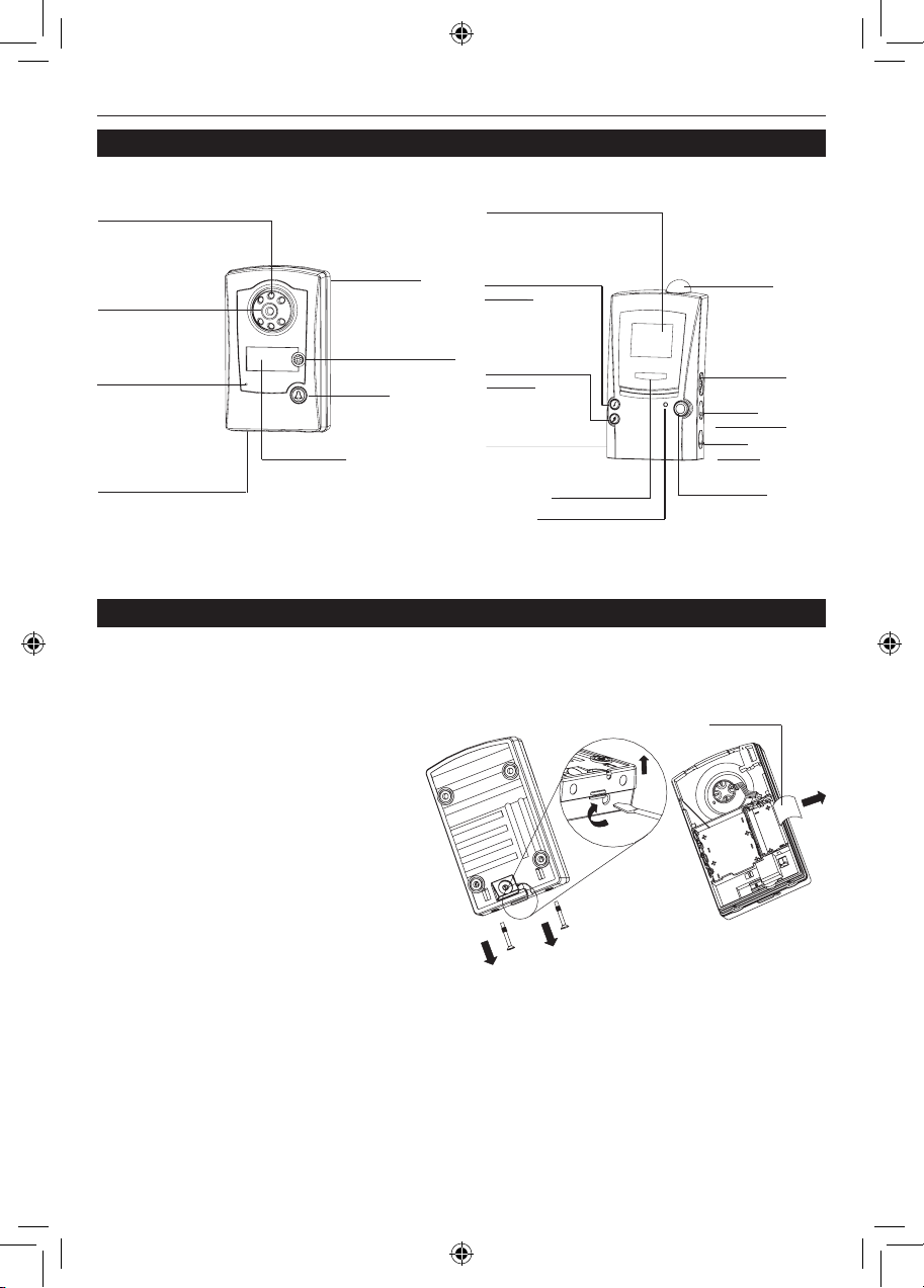
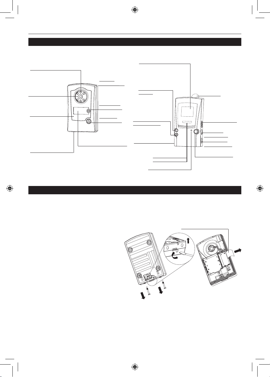
Features
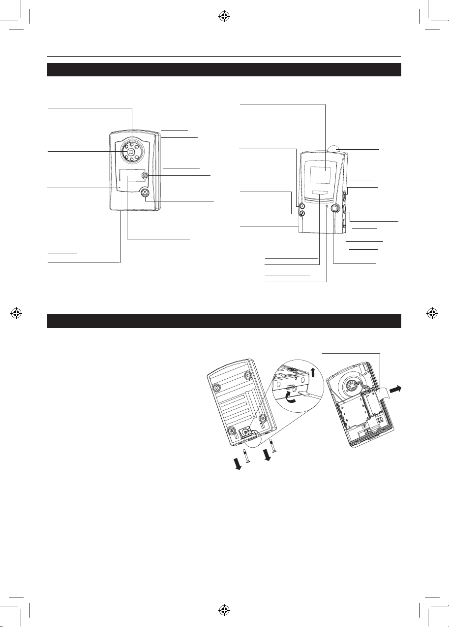
DOOR CAMERA FEATURES
CAMERA LENS
CONFIDENCE LIGHT
– VIEWS CALLERS
INFRARED LEDS
– ALLOWS THE CAMERA
TO ‘SEE IN THE DARK’ IN
MONOCHROME
CALL BUTTON
– ACTIVATES THE
CHIME TUNE
AND CAMERA
NAME PLATE
– FOR DISPLAYING YOUR
NAME OR OTHER INFORMATION
LIGHT SENSOR
– DETECTS AMBIENT LIGHTING AND
SWITCHES CAMERA FROM COLOR
TO MONOCHROME IN LOW LIGHT
– ILLUMINATES WHEN
CALL BUTTON IS
PRESSED TO
REASSURE THE
CALLER THAT THE
UNIT IS WORKING
CAMERA BASE
– REMOVES FOR
WALL MOUNTING
MOVEMENT SENSOR
(PIR)
RECEIVER FEATURES
SCAN BUTTON
– LOOKS FOR
CONNECTED
CCTV-TYPE CAMERAS
TUNE SELECTION
BUTTON
– SELECTS THE
CHIME TUNE FOR
THE DOOR CAMERA
CHIME
VOLUME
Scan
RCA SOCKET
– TO CONNECT TO
A TV SET (OPTIONAL)
ANTENNA
– RECEIVES THE
SIGNAL FROM
THE CAMERA
DISPLAY
– SCREENS THE CAMERA
IMAGE FOR APPROX. 30
SECONDS AFTER THE CALL
BUTTON IS PRESSED
DISPLAY
BRIGHTNESS
MIC VOLUME
VISIOCA
M
– FOR FUTURE USE
TUNE SELECTION
BUTTON
– FOR SECOND
CAMERA/PUSH
BATTERY INDICATOR
CHIME FLASHER
Pre-installation setup
Before fixing the door camera in place, set up and test the system as follows:
Install the batteries in the door camera
Note: The door camera has a built
in tamper switch to help prevent
theft. Once the batteries have been
inserted, the confidence light flashes
and the tamper alert sounds on the
receiver.
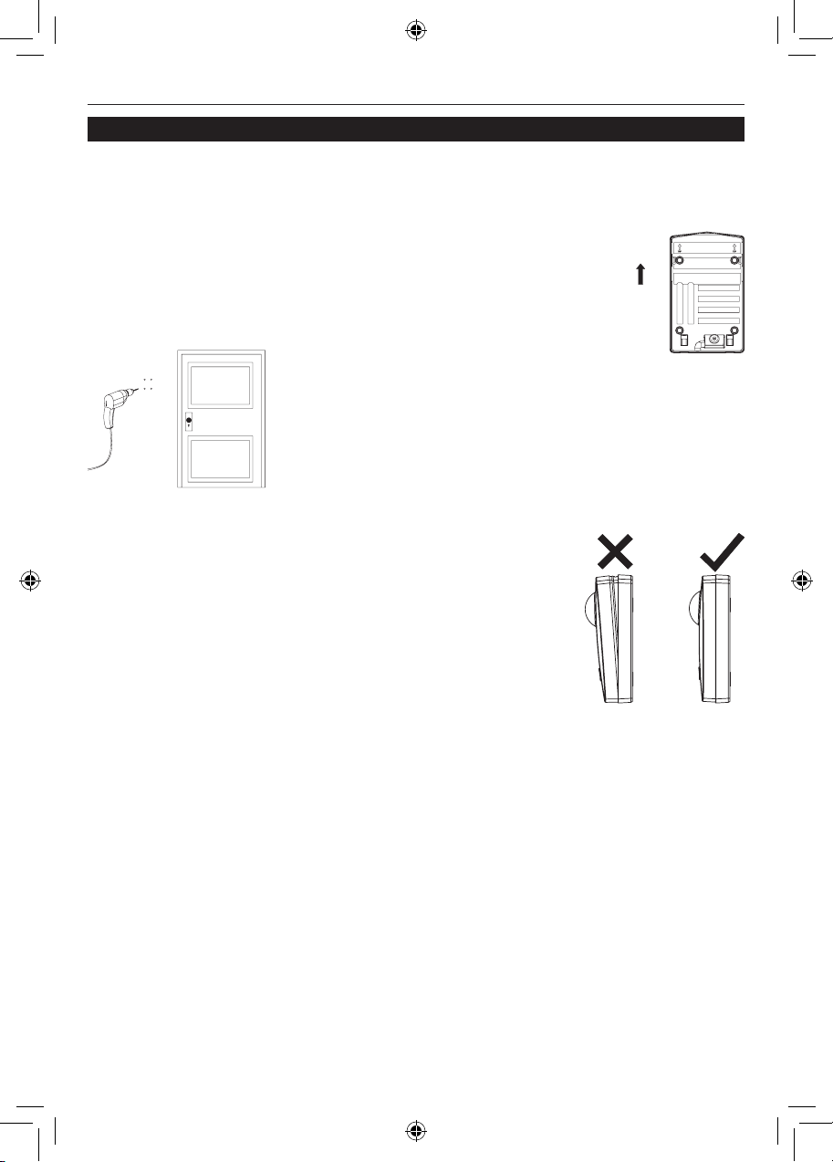
1. Remove the two screws at the
base of the camera unit and
unhook and release the camera
base, pulling it away from the
lower end first.
3
1 2
NAMEPLATE
69-2108EFS_A.indd 1 11/30/2007 1:51:45 PM
Page 4
Installation and Use
69-2108EFS—01 2
Pre-installation setup
Note: Removing the cover also provides access to the nameplate, so now is a good
time to write your name or other information. To use the nameplate, pull the end out
from the side of the battery compartment, add your text at the end of the strip and
carefully push it back into the slot.
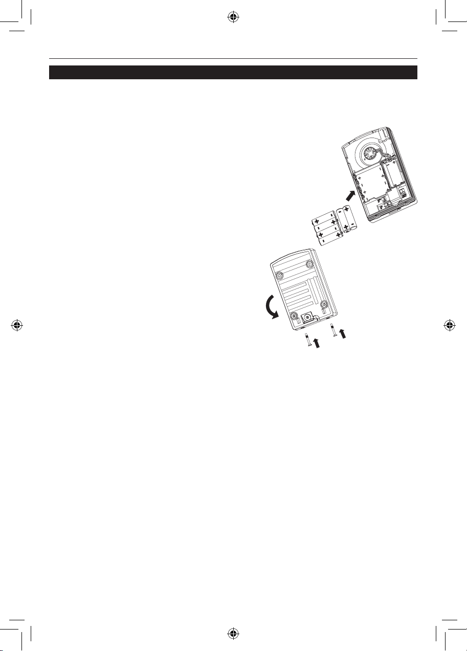
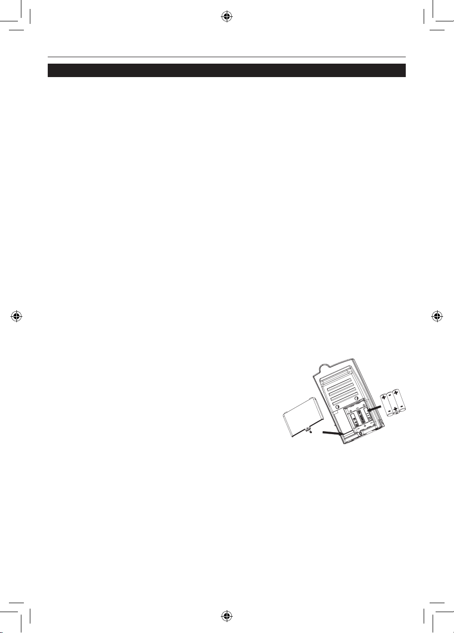
2. Insert six AA-size alkaline batteries in the battery
compartment at the back of the door camera – as
in the following diagram. Follow the plus (+) and
minus (–) signs on the diagram inside the battery
compartment. Never mix old and new batteries.
3. Refit the camera base and insert the
screws to stop the tamper alert from
sounding.
Note: There is an option to power the door
camera using an 8–10V transformer. See ‘Door
Camera Transformer option’ at the end of this
section for details.
1
3
2
69-2108EFS_A.indd 2 11/30/2007 1:51:45 PM
Page 5

VISIOCAM
3 69-2108EFS—01
Pre-installation setup
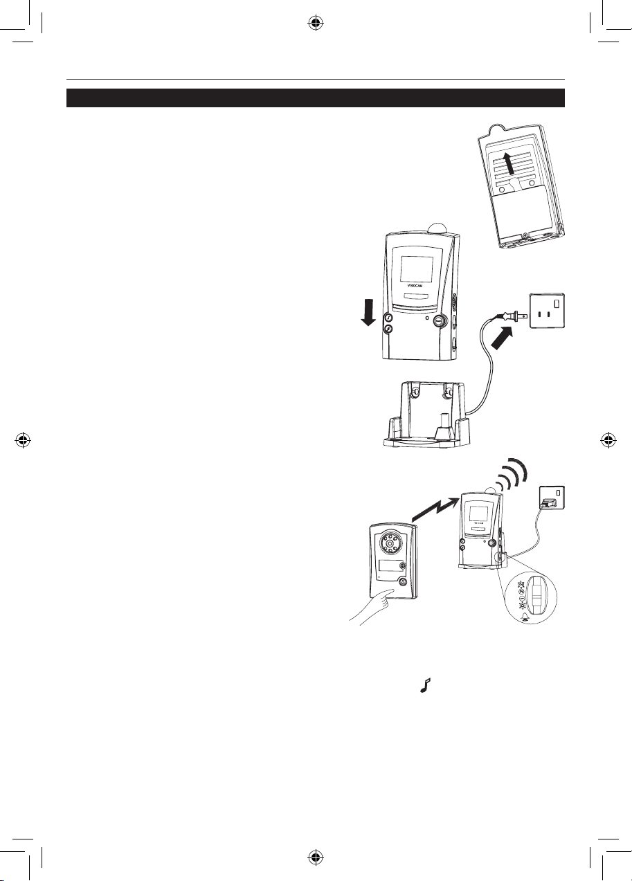
Charge the receiver batteries
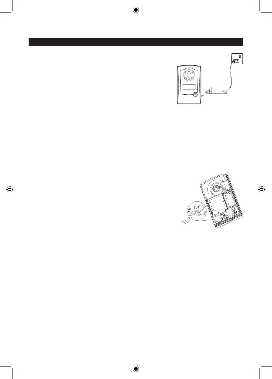
1. Remove the battery isolating tab at the rear of the portable
receiver.
2. Place the receiver onto the charging base and plug the
charging base into a suitable mains socket.
The battery indicator flashes slowly if this is
the first time the unit has been powered up; the
chime tunes play once the batteries have enough
power.
Before the next step, leave the unit to charge
for at least three hours so that the batteries
have enough power for the LCD screen. The
receiver takes about 12 hours to be fully charged.
Note that the charging base and rear of the
receiver will get warm in use: this is normal.
2
1
Program the door camera into the receiver
Ensure the door camera and receiver are separated by at least 6 ft. (2 m).
To program the door camera into the receiver,
press and hold the call button on the door camera until the receiver responds with a tune and
displays the image captured by the camera.
Once the door camera has been programmed
into the receiver, the receiver remains active in
program mode for approximately two minutes.
Note: You can select another tune by pressing
the ‘ ’ button.
69-2108EFS_A.indd 3 11/30/2007 1:51:45 PM
Page 6
Installation and Use
69-2108EFS—01 4
Installing the door camera
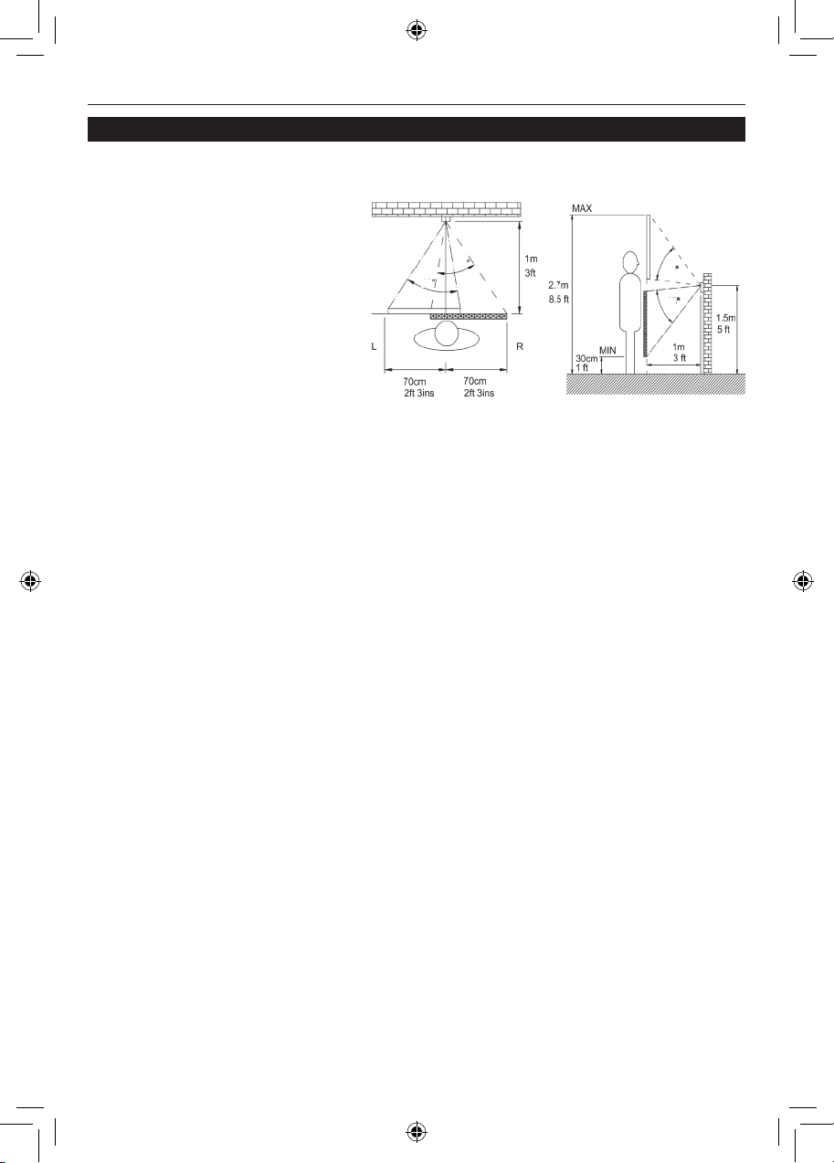
Position the door camera
Find a position for the door camera where the call button is easy
to press and the camera can ‘see’
visitors clearly.
The following points are important:
• The height needs to be
between 4.5 and 5 ft. (1.3 and
1.5 m) above the ground or
step where visitors normally
stand.
• The camera is adjustable through a 30° total angle left to right, and 60° top to
bottom. Position the unit to ensure the camera has sight of your visitor.
• Avoid a position where the camera faces into the sun, as this may overload the
camera and visitors will appear very dark. Facing large areas of bright sky should
also be avoided when possible by pointing the camera down, rather than up.
• Position the camera where the motion sensor is not blocked from approaching
visitors. Avoid locating the camera where passing people or traffic will cause
false triggering. Note that the motion sensor range is approximately 12 ft (4 m)
and that it can be switched off if necessary (see ‘Door camera’, page 10).
• The mounting surface should be of brick or wood construction, and not of
metal, reinforced concrete, or heavy stone (i.e. more than 16 in. [40 cm] thick)
construction – as this may block the transmitted signal.
• The mounting surface should be even and flat, to avoid distorting the door
camera case, level any uneven surface before mounting, as a distorted base can
let rainwater into the unit.
• Do not mount within 12 in. (30 cm) of large metal objects, or steel reinforced PVC
frames, as this reduces or blocks signals to the receiver.
• Keep the base of the door camera clear of shelves or other projections that
might block the light sensor under the unit. An obscured sensor causes the
camera to switch into black and white mode.
• If the door camera is to be powered separately, power cable must also be
considered.
HORIZONTAL
TOP VIEW
VERTICAL
57
57
41
41
69-2108EFS_A.indd 4 11/30/2007 1:51:47 PM
Page 7

VISIOCAM
5 69-2108EFS—01
Installing the door camera
Position the receiver
The receiver must be positioned within range of the door camera (i.e. less than 60 ft.
(20 m) in a typical building).
Test the system
To ensure reliable operation, we recommend that both the door camera and receiver
are powered up in their planned position(s), to check that the receiver has a good signal from the door camera.
To test the system, have someone hold the door
camera against the wall in the selected mounting
position and press the call button, while you check
the reception on the receiver unit.
If the picture quality is poor, or there is no response
when the call button is pressed, then there are three
possible reasons:
1. The units may be too far apart (more than 60–90 ft. [20–30 m] in a typical house).
Try moving the receiver closer.
2. There is nearby interference on the video channel. Remove the door camera
back and change the video channel switch from CH 1 to, for example, CH 3. Test
the system again, selecting a different channel if channel 3 is no better.
Refer to the troubleshooting section for more information on interference reduction.
3. The door camera has not been programmed into the receiver (refer to page 3).
Adjust the camera angle
With the door camera at the intended position, you may need to
adjust the camera lens to cover the desired observation area.
Open the back of the door camera and adjust the camera eyeball
from the back of the product. Note that there is more camera movement available in the Up/Down than in the Left/Right direction.
69-2108EFS_A.indd 5 11/30/2007 1:51:47 PM
Page 8
Installation and Use
69-2108EFS—01 6
3. Fix the door camera base in place using the screws and
wall plugs provided.
4. Hook the door camera into the base at the top first, then
push and click it in at the bottom. Check that the unit is
evenly pressed in place to seal the unit from rain damage.
Make sure that the sealing strip on the camera front
remains in place. Insert the two screws underneath, and
tighten.
Check that the unit is working after installation by pressing the
call button, the confidence light should illuminate.
Installing the door camera
Mount the door camera
Do not mount the camera in wet conditions as moisture or condensation will affect
the internal parts.
Once you have tested the system in place, mount the camera onto a
wall or door as follows:
1. Remove the two screws underneath the door camera. Unhook
and release the front and pull it away from the base. Note the
TOP arrow on the base.
TOP
2. If mounting to a wall, mark the location of the four
mounting holes using the camera base as a template.
Drill using a 1/4-in. (6 mm) masonry bit. The distance
between mounting holes is 2.8 in. (72 mm) horizontally
and 3.6 in. (92 mm) vertically.
69-2108EFS_A.indd 6 11/30/2007 1:51:47 PM
Page 9
VISIOCAM
7 69-2108EFS—01
Door camera transformer option
For installations where there is frequent use, typically
more than five uses per day, the door camera can be
powered using an 8–10 volt, 1 amp transformer.
Important: Higher voltage transformer might damage the
camera.
Connect the low voltage output of the transformer to the
door camera using suitable low voltage cable such as bell wire. Maximum recommended outer cable diameter is .2 in (5 mm). The cable run should not exceed 100 ft.
(30 m).
A cable inlet with a water seal is provided in the rear of the door camera. To connect
up the transformer:
1. Feed the power cable through the cable inlet and connect it to the power
terminals. Leave about 6 in. (15 cm) of cable free between the base and the door
camera body, for later service access. Do not fit batteries.
2. Secure the door camera in place. Check that the front is fully and evenly
pressed in to seal the unit against rain damage.
3. Secure the cable using clips or tacks as appropriate.
4. Connect the other end of the power cable to the secondary
(8V output) of an unpowered bell transformer. Follow
the transformer instructions carefully for correct
connections.
5. Connect the mains terminals of the transformer
to a suitable, always on, mains supply.
Test the door camera by pressing the call button: the confidence light should illuminate.
Note: If you have not used the door camera with batteries for a trial test, then you
must program the door camera with the receiver by following the ‘program the door
camera into the receiver’ instructions.
Installing the door camera
TRANSFORMER
8V / 1 A
TO THE
TRANSFORMER
69-2108EFS_A.indd 7 11/30/2007 1:51:48 PM
Page 10
Installation and Use
69-2108EFS—01 8
Receiver operation
When the call button is pressed on the door camera, the receiver chimes (provided
the volume switch is not set to 0) and the camera image is displayed for about thirty
seconds. If the caller presses the call button again, then the display time will extend
to another 30 seconds. Video transmission
is limited to 30 seconds to conserve camera battery life and is not adjustable.
When the batteries need recharging, a
camera image is no longer shown – the
chime alone sounds (unless the battery
level is too low for sound).
Charging base
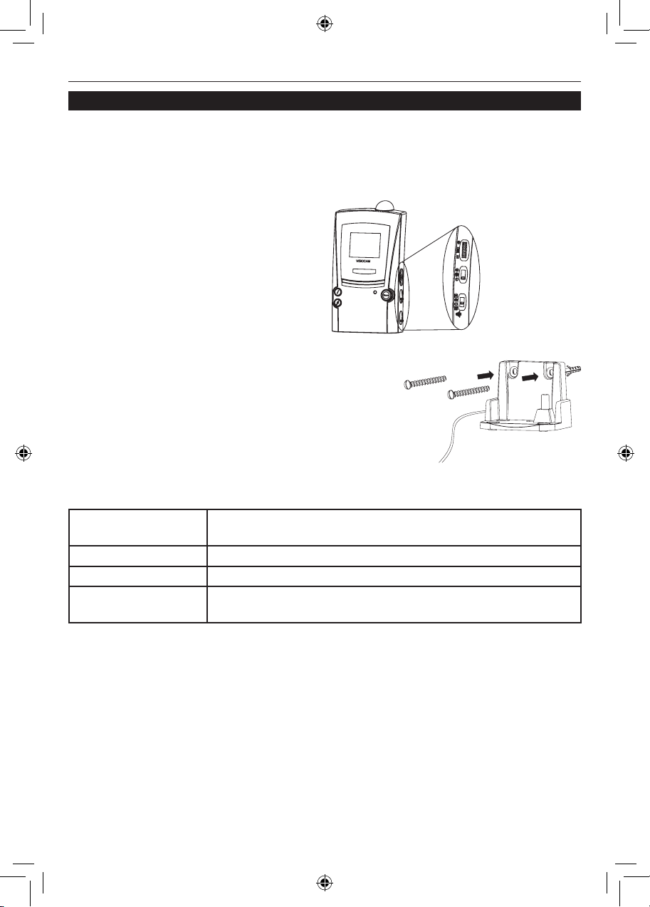
Like a portable phone, keep the receiver topped up on the charging base for reliable
operation. Depending on use, the receiver should operate for several days off the charging base. The charging base can be used on a flat surface or mounted to a
wall using the supplied screws and wall plugs. Before
mounting in place, check that the receiver can pick up
a good signal at the intended position.
Installing the receiver
MIC VOLUME [FOR
FUTURE USE]
DISPLAY BRIGHTNESS
CHIME VOLUME
Battery indicator
The indicator behaves as follows:
Remains on when the receiver is on the charging base and is fully
charged.
Blinks once a second when the receiver is charging.
Remains off when the receiver is off the charger and the batteries are OK.
Blinks slowly once
every ten seconds
when the receiver is off the charging base and needs
recharging.
Chime flasher
Flashes to indicate a call when the chime volume control is in position 0 or 2*.
Display brightness
Activate the door camera by pressing its call button, then adjust the receiver display
for best viewing by using the four position slide switch. One step down from maximum brightness is the recommended setting.
Chime volume control
The chime volume level can be set to using the lowest slide switch of the three (see
diagram above). Adjust to high level (2), low level (1), or off (0).
69-2108EFS_A.indd 8 11/30/2007 1:51:48 PM
Page 11
VISIOCAM
9 69-2108EFS—01
Installing the receiver
Chime tune selection
The receiver chime tune can be changed by pressing the ‘ ’ button.
Chime tune options are as follows:
• Two note bell (Default tune for door camera)
• Saxophone (Default tune for second door camera or bell push)
• Single note bell
• Knock
The ‘ ’ button changes the chime tune for a second door camera or a door push.
Night operation
In good daylight conditions, the receiver displays a color picture. In low lighting or at
night the display automatically switches to black and white. Infrared LEDs illuminate
the caller, so they can be viewed on the receiver even when surrounded by complete
darkness.
Low camera battery indication
When the batteries in the door camera are running low, the receiver indicates this with a
double beep warning tone that follows the chime when a visitor presses the call button.
Replace the batteries in the door camera within one week of a low battery alert.
Tamper alert tone
If someone attempts to remove the door camera by unscrewing the cover screws, the
tamper alert tone is triggered, beeping for 30 seconds. Check outside immediately.
Press any button on the front of the receiver to stop the alert tone. The alert tone is
unaffected by the chime volume switch.
Note: The alert is also triggered when you undo the cover to replace batteries in the
door camera.
MIC volume
[For future use] The topmost control along the side (see diagram on page 8) will control the volume produced from a microphone. Adjust for optimum listening level.
Scan button
When used in a multi-camera system, this button scans through available pictures.
Privacy
Remember that this product uses the public airwaves, and that the 30-second duration video signal from the door camera(s) can be picked up by nearby 2.4GHz video
receiving devices.
69-2108EFS_A.indd 9 11/30/2007 1:51:49 PM
Page 12

Installation and Use
69-2108EFS—01 10
Motion sensor
The PIR (‘Passive InfraRed’) sensor activates the door camera automatically. The
receiver produces a ‘ping’ sound and displays the door camera image for approximately 30 seconds.
If the motion sensor is not required, then it can be disabled.
To switch the motion sensor off, press and hold the call button on the camera for
more than ten seconds. The confidence indicator blinks rapidly to confirm that the
motion sensor is disabled.
To switch the motion sensor back on, press and hold the call button for more than ten
seconds, the confidence indicator remains on for two seconds to confirm.
Note: Power loss to the camera or a change of batteries will reset the sensor back on.
Door camera
69-2108EFS_A.indd 10 11/30/2007 1:51:49 PM
Page 13
VISIOCAM
11 69-2108EFS—01
Expanding your system
There are many ways to expand your entry system: you can connect your system to a
television set or add more cameras, for example.
TV connection
You can connect the receiver to a TV set via the accessory RCA lead provided.
Connect the stereo plug to the VisioCam receiver unit and plug the yellow RCA plug
to the TV AV input. Set the TV channel to the default AV channel for the said RCA
input (refer to TV set instructions).
When the door camera is activated, the VisioCam receiver will chime and the TV will
display the image of the visitor.
Note: The TV needs to be set at the default channel manually in order to display the
image. Auto switching function not available.
Adding a door push
The receiver will respond to a Visiocam door push. To program a door push into the
receiver:
1. Press and hold the ‘ ’ button for approximately five seconds until the receiver
beeps three times
2. Press the door push button until the receiver sounds.
Note: The video receiver does not respond to a door push while the video screen is
active.
Additional door cameras
The receiver will respond to up to four door cameras.
Each camera must be set on a different video channel (1–4), and be programmed
into the receiver. Refer to the instructions provided with the additional unit, or see ‘To
reprogram or reset the receiver’, in this section.
To reprogram or reset the receiver
A. To add another door camera or bell push:
Press and hold the ‘ ’ button for more than five seconds, the unit will beep three times
and enter programming mode for approximately two minutes. During the two minute
programming time, press the call button or button on the new unit to program it in. The
unit must be within 30–60 ft. (10–20 m) of the receiver to ensure reliable programming.
B. To clear all programmed data, e.g. when replacing a door camera:
Press and hold both the ‘ ’ and ‘ ’ buttons in for five seconds to clear the pro-
grammed data and enter programming mode. The available chime sounds play.
Follow the programming sequence under Receiver Setup.
69-2108EFS_A.indd 11 11/30/2007 1:51:49 PM
Page 14

Installation and Use
69-2108EFS—01 12
CARE AND MAINTENANCE
• Fingerprints or dirt on the door camera lens can cause a dull or blurred picture.
Occasionally use a soft, damp cloth to wipe the surface. Do not use cleaning
products. Over-zealous or too frequent cleaning will scratch the surface and blur
the picture.
• Keep the receiver and charger base away from rain, liquids or risk of liquid
spillage.
• Do not place rings or other metal objects over the peg in the charging unit – they
will become hot to the touch!
• Do not allow any rain or moisture to become trapped inside the door camera, as
it may damage the internal parts.
• Avoid replacing door camera batteries during wet weather.
• Do not take the products apart; there are precision components inside which are
easily damaged.
• Avoid dropping or strong shocks to either unit.
• Only use the included or recommended power supply.
• Do not use or store either unit in dusty, dirty areas.
REPLACING THE RECEIVER BATTERIES
Constant use will eventually reduce the capacity of the rechargeable batteries, and
reduce the receiver life off the charger base. Replace the batteries by unscrewing the
single battery cover screw at the bottom rear of the receiver.
Remove the old batteries and replace with three NiMH type
AA batteries with a minimum capacity of 1200mAH. Follow
the battery orientation symbols in the battery compartment.
Replace the battery cover and cover screw.
Maintenance and use
2
1
69-2108EFS_A.indd 12 11/30/2007 1:51:49 PM
Page 15

VISIOCAM
13 69-2108EFS—01
Troubleshooting
The system does not work…
• Make sure the door camera is powered, refer to below.
• Make sure the receiver is powered, refer to below.
• Move the receiver closer to the door camera to receive a better signal.
• If new, make sure the door camera is programmed to the receiver – see ‘Preinstallation Setup’ on page 3.
Door camera is not powered…
This is indicated when the red confidence light on the front does not light when the
call button is pressed. Check:
• The batteries are all inserted in the right direction.
• The batteries are new and Alkaline type.
• If transformer powered, the transformer is connected to the mains and powered on.
• There is no damage to the transformer connecting cable.
• The two wires in the transformer connecting cable are making contact to the
terminals in the unit and in the transformer.
Receiver is not powered…
• The batteries are discharged. Place the receiver on the charging unit for a minimum
of 12 hours to fully recharge the batteries. The receiver battery indicator will blink
once a second to indicate charging, and will stay on when the receiver is fully
charged.
The receiver only displays a black and white picture…
• The light level at the door camera is very low.
• The light sensor under the door camera is covered, is too close to an adjacent
object, or is facing a very black surface.
The signal is poor, or there is interference…
• The receiver is in a signal ‘dead spot.’ Rotate or move the receiver 20 in. (50 cm)
and try again. People walking near the receiver can also temporarily affect the
reception quality.
• Make sure that the receiver is in range of the door camera, approximately 100 ft.
(30 m) in a typical building. Move the receiver closer to see if the picture improves.
If this does not improve the picture then there is nearby interference on the video
channel. Open the door camera and change the video channel switch from 1 to 3,
for example.
• If there is more than one video transmitter (door camera or others), every unit must
have its video channel switch set to a different channel.
• A microwave oven may be in use in the path between the door camera and receiver.
Move the microwave oven or turn it off.
• Computers and other IT equipment can radiate signals and affect the video quality.
If this is a likely problem, move the receiver away (at least 3 ft. [1 m]) from the units.
The receiver chimes, followed by a beep-beep…
This indicates low battery power in the door camera. Replace the door camera
batteries.
69-2108EFS_A.indd 13 11/30/2007 1:51:49 PM
Page 16

Installation and Use
69-2108EFS—01 14
A beep-beep tone sounds for 30 seconds…
This is an alert triggered by the tamper switch indicating someone is trying to
unscrew and remove the door camera. Check outside immediately.
The tone may sound if the screws that mount the front of the door camera to the rear
are not fully screwed in place.
Press any button on the receiver to stop the alert tone.
The receiver switches on randomly…
This is probably due to the motion sensor on the camera picking up passers by, passing cars or moving heat sources.
Switch the PIR sensor off, (refer to the ‘DOOR CAMERA’ section), block off the
unwanted movement, or relocate the door camera.
Chime sounds but the picture is displayed for only a few seconds…
• The video signal has been interrupted. Press the Scan button to recapture the video
signal, move the receiver to another position nearby.
• If this occurs regularly, locate the receiver closer to the door unit, or place the
receiver higher up. Generally, the receiver will receive a stronger signal up on a
shelf, and a weak signal near the floor.
• The battery charge is low. Place the receiver on the charger for at least four hours
to recharge the batteries.
Troubleshooting
69-2108EFS_A.indd 14 11/30/2007 1:51:49 PM
Page 17

VISIOCAM
15 69-2108EFS—01
About your new thermostat
Specifications
Door Camera Receiver
Power requirement 110V AC ±10% via charger
Battery type 6 x AA-size alkaline batteries 3 x AA-size NiMH batteries, mini-
mum 1200mAh
Battery operating life typically one year* typically 3 days from full charge*
Motion sensor range 12 ft. (4 m) typical (fixed sensitiv-
ity)
N/A
Optional power via 8V to 10V 1A bell transformer**
or 8–12V AC or DC supply
N/A
Maximum number of transmitters
(video or door push) programmable per receiver
N/A 4 (1, 2 with selectable chime tune;
3, 4 with fixed chime tune)
Sound output N/A 80dBA/3 ft (1 m) (position 2)
Operating frequency 433MHz and 2.4GHz 433MHz and 2.4GHz
RF output level <1mW N/A
Antenna type (built in) omnidirectional omnidirectional
Camera type CMOS sensor
Effective resolution 628 x 582 pixels TFT LCD true color display
Video standard NTSC NTSC
Settable Video channels 4 4, with auto detection
Video output N/A 1Vpp 75W
Color to B/W changeover Approx. 100 lux brightness
Operating temperature 14°F to 104°F
–10°C to 40°C
32°F to 104°F
0°C to 40°C
Weight 13 oz. (340 g) (without batteries) 13 oz. (340 g) (with batteries)
Size H x W x D 6.3 x 3.8 x 1.9 in.
(160 x 97 x 49 mm)
6.3 x 3.4 x 1.8 in.
(160 x 86 x 47 mm)
Rain proof Pass UL1598 rain test N/A
* Based on three calls per day in a temperate climate. More frequent use, or operation in a low temperature
environment 14°F to 41°F (–10°C to 5°C) will reduce battery life.
69-2108EFS_A.indd 15 11/30/2007 1:51:50 PM
Page 18

® U.S. Registered Trademark.
© 2007 Honeywell International Inc.
69-2108EFS—01 M.S. 11-07
Printed in U.S.A. on recycled
paper containing at least 10%
post-consumer paper fibers.
Honeywell International Inc.
ACS, Environmental and Combustion Controls
1985 Douglas Drive, Golden Valley, MN 55422
www.honeywell.com
DECLARATION
Honeywell hereby declares that this product complies with Part 15 of the FCC rules and
Industrial Canada standards. This device operation is subject to the following two conditions:
(1) This device may not cause harmful interference, and (2) This device must accept any interference received, including interference that may cause undesired operation. Caution: Changes or
modifications not expressly approved by the party responsible for regulatory compliance could
void the user’s authority to operate the equipment.
The charging base is in compliance with relevant standards in CUL and UL60065 safety
requirements.
GUARANTEE
Honeywell guarantees this product for 1 year from the date of purchase. Proof of purchase is
required; this does not affect your statutory rights. If you require further information about your
product, call the Honeywell helpline at 1-800-468-1502
DISPOSAL AND RECYCLING
Batteries and waste electrical products should not be disposed of with household waste. Please
recycle where these facilities exist. Check with your local authority or retailer for recycling
advice.
69-2108EFS_A.indd 16 11/30/2007 1:51:50 PM
Page 19

Guide
d’installation et
mode d’emploi
VISIOCAMTM RCWL8000A et RPWL800A
Système de carillon vidéo sans fil
69-2108EFS_A.indd 17 11/30/2007 2:00:34 PM
Page 20

69-2108EFS—01 18
Guide d’installation et mode d’emploi
Table des matières
Description du produit ........................... 19
Le système VisioCam ..............................18
Vérification du contenu de la boîte ......... 18
Installation .............................................20
Avant l’installation ....................................20
Installation de la caméra de porte ........22
Option de transformateur
de caméra de porte .................................25
Installation du récepteur .......................26
Utilisation du récepteur ...........................26
Caméra de porte ......................................28
Expansion du système ...........................29
Maintenance et utilisation .....................30
Soin et entretien .......................................30
Remplacement des piles du récepteur...30
Dépannage ............................................... 31
Caractéristiques techniques .................33
Déclaration ...............................................34
Garantie .................................................... 34
Élimination et recyclage ..........................34
Merci d’avoir choisi ce produit Honeywell. Nous vous demandons de respecter
les instructions pour bien installer le produit et en faire une utilisation correcte.
Conservez ce document dans un endroit sûr pour référence ultérieure.
Avant de monter la caméra de porte ou le récepteur de façon permanente, assurez-vous d’avoir testé les deux unités et vérifiez que le système
fonctionne bien à l’emplacement que vous avez choisi. (Voir la section
«Installation», à la page suivante).
Votre système d’entrée vidéo sans fil Honeywell fait appel à des signaux radio pour
transmettre de la caméra de porte au récepteur une image vidéo du visiteur. Le système est évolutif, vous permettant ainsi d’installer des caméras de surveillance supplémentaires ou une deuxième caméra de porte au besoin.
VÉRIFICATION DU CONTENU DE LA BOÎTE
Les éléments suivants sont inclus dans
l’emballage :
Ensemble de carillon
• Unité de transmission (caméra de
porte)
• Unité de réception avec affichage à
cristaux liquides
• Socle de recharge du récepteur
• Câble de connexion RCA
• Six vis nº 8 pour la fixation au mur
• Six chevilles d’ancrage
Caméra seulement
• Unité de transmission (caméra de
porte)
• Four vis nº 8 et chevilles d’ancrage
pour la fixation au mur
Vous aurez besoin de :
• 6 piles alcalines AA pour la caméra
de porte
• Un tournevis cruciforme nº 2
• 1 foret de maçonnerie de 6 mm
• Un grand tournevis plat
69-2108EFS_A.indd 18 11/30/2007 1:51:51 PM
Page 21
VISIOCAM
19 69-2108EFS—01
CAMÉRA DE PORTE
LENTILLE
LAMPE TÉMOIN
– VISUALISE LES
VISITEURS
VOYANTS DEL INFRAROUGES
– PERMETTENT À LA
CAMÉRA DE «VOIR DANS
L’OBSCURITÉ»
EN MONOCHROME
BOUTON D’APPEL
– DÉCLENCHE LA
MÉLODIE DU
CARILLON ET
LA CAMÉRA
PLAQUE D’IDENTITÉ
– POUR AFFICHER VOTRE
NOM OU TOUTE AUTRE
INFORMATION
CAPTEUR
PHOTOÉLECTRIQUE
– DÉTECTE LA LUMIÈRE AMBIANTE
ET FAIT PASSER LA CAMÉRA DU
MODE COULEUR AU MODE NOIR ET
BLANC LORSQU’IL NE FAIT PAS ASSEZ CLAIR
– S’ALLUME LORSQUE
LE BOUTON D’APPEL
EST ACTIONNÉ, POUR
CONFIRMER AU
VISITEUR QUE L’UNITÉ
FONCTIONNE BIEN
BASE DE
LA CAMÉRA
– SE DÉTACHE
POUR LA FIXATION
AU MUR
DÉTECTEUR
DE MOUVEMENT
PASSIF À
INFRAROUGE (PIR)
RÉCEPTEUR
BOUTON SCAN
– RECHERCHE DES
CAMÉRAS DE TYPE
CIRCUIT FERMÉ
CONNECTÉES
BOUTON MÉLODIE
– SÉLECTIONNE LA
MÉLODIE DE
CARILLON POUR LA
CAMÉRA DE PORTE
VOLUME DU
CARILLON
Scan
PRISE RCA
– POUR
RACCORDEMENT À UN
TÉLÉVISEUR (OPTIONNEL)
ANTENNE
– REÇOIT LE
SIGNAL À PARTIR
DE LA CAMÉRA
AFFICHEUR
– AFFICHE L’IMAGE DE LA
CAMÉRA PENDANT ENVIRON
30 SECONDES APRÈS QUE
LE BOUTON D’APPEL A
ÉTÉ ACTIONNÉ
LUMINOSITÉ DE
L’ÉCRAN
VOLUME
DU MICRO
VISIOCA
M
– POUR
UTILISATION
FUTURE
BOUTON MÉLODIE
– POUR
DEUXIÈME
CAMÉRA/BOUTON
DE SONNETTE
INDICATEUR DE
NIVEAU DE CHARGE
SIGNAL LUMINEUX
DE CARILLON
Avant l’installation
Avant de fixer définitivement la
caméra de porte, préparer et vérifier
le système comme suit :
Insertion des piles dans la caméra
de porte
Remarque : la caméra de porte
comporte un contact anti-sabotage
pour prévenir les vols. Une fois
les piles insérées, la lampe témoin
clignote et l’alerte anti-sabotage
sonne au récepteur.
1. Retirer les deux vis à la base de
la caméra, puis décrocher et libérer la base de la caméra, en tirant d’abord par le
bas.
3
1 2
PLAQUE D’IDENTITÉ
Description du produit
69-2108EFS_A.indd 19 11/30/2007 1:51:51 PM
Page 22

69-2108EFS—01 20
Guide d’installation et mode d’emploi
Remarque : le fait de retirer le couvercle donne également accès à la plaque
d’identité; il est donc opportun d’y écrire maintenant votre nom ou toute information.
Pour utiliser la plaque d’identité, tirer l’extrémité sur le côté du compartiment des
piles, ajouter le texte au bout de l’étiquette et la remettre
soigneusement en place.
2. Insérer 6 piles alcalines AA dans le compartiment
prévu à cet effet au dos de la caméra de porte
(comme sur l’illustration). Observer les signes (+) et (-)
du schéma à l’intérieur du compartiment. Ne jamais
mélanger de vieilles piles avec des neuves.
3. Replacer la base de la caméra et insérer
les vis pour arrêter l’alarme anti-sabotage.
Remarque : il existe une option permettant
d’alimenter la caméra de porte par un transformateur de sonnerie de 8–10 V. Voir la section
«Option de transformateur de caméra de porte»
à la fin de cette section pour de plus amples
détails.
1
3
2
Avant l’installation
69-2108EFS_A.indd 20 11/30/2007 1:51:52 PM
Page 23

VISIOCAM
21 69-2108EFS—01
Chargement du récepteur
1. Retirer la languette de protection des piles à l’arrière du
récepteur portatif.
2. Placer le récepteur sur le socle de chargement, et brancher
celui-ci dans une prise de courant.
Le voyant de piles clignote lentement si l’unité
est mise sous tension pour la première fois ; le
carillon retentit une fois lorsque les piles sont
rechargées.
Avant l’étape suivante, laisser l’unité se
recharger pendant au moins trois heures,
pour que les piles aient suffisamment de réserve
pour l’écran à cristaux liquides. Il faut environ 12
heures au récepteur pour se recharger complètement.
Noter que le socle de chargement et l’arrière du
récepteur chauffent pendant l’utilisation : cela est
parfaitement normal.
2
1
Programmation de la caméra de porte dans
le récepteur
Voir à ce que la caméra de porte et le récepteur
soient séparés d’au moins 2 m (6 pi).
Pour programmer la caméra de porte dans le
récepteur, appuyer sur le bouton d’appel de
la caméra de porte et le maintenir enfoncé
jusqu’à ce que le récepteur réponde par une
mélodie et affiche l’image saisie par la caméra.
Une fois la caméra de porte programmée dans
le récepteur, celui-ci reste en mode de programmation pendant environ deux minutes.
Remarque : On peut sélectionner une autre mélodie en appuyant sur le bouton ‘ ’.
Avant l’installation
69-2108EFS_A.indd 21 11/30/2007 1:51:53 PM
Page 24

69-2108EFS—01 22
Guide d’installation et mode d’emploi
Positionnement de la caméra de
porte
Positionner la caméra de porte de
sorte qu’elle puisse «voir» clairement les visiteurs et que le bouton
d’appel soit facile d’accès.
Les points suivants sont importants :
• La hauteur doit être comprise
entre 1,3 et 1,5 mètre (4,5
et 5 pi) au-dessus du sol ou
de la marche sur laquelle les
visiteurs se tiennent normalement.
• L’angletotald’ajustementdelacaméraestde30˚degaucheàdroiteetde60˚
de haut en bas. Positionner l’unité de manière à ce que la caméra puisse voir
votre visiteur.
• Éviter les positions où la caméra ferait face au soleil, car cela pourrait saturer la
caméra et les visiteurs apparaîtraient alors très sombres. La caméra ne doit pas
non plus faire face à de grandes portions de ciel clair. Pointer la caméra vers le
bas plutôt que vers le haut.
• Placer la caméra de sorte que le détecteur de mouvement ne soit pas obstrué
et capte correctement le mouvement des visiteurs s’approchant de la caméra.
Éviter de placer la caméra dans un endroit de passage intense de personnes ou
de véhicules, faute de quoi de fausses alarmes seront déclenchées. Noter que le
détecteur capte le mouvement à 4 m (12 pi) environ et peut être mis hors service
au besoin (voir la section «Caméra de porte» à la page 28).
• L’unité doit être montée sur une surface en brique ou en bois, et non sur du
métal, du béton armé ou de la pierre lourde (plus de 40 cm [16 po] d’épaisseur);
cela risquerait en effet de bloquer le signal de transmission.
• La surface de fixation doit être uniforme et plane afin d’éviter que la boîte de la
caméra de porte ne se torde. Il est important que les surfaces inégales soient
nivelées car les eaux de pluie risqueraient de pénétrer dans une boîte de caméra
tordue.
• Ne pas installer à moins de 30 cm [12 po] d’objets métalliques de grande taille
ou de panneaux PVC renforcés à l’acier; cela réduit ou bloque en effet les
signaux transmis vers le récepteur.
• Tenir la base de la caméra de porte à l’écart de toute étagère ou de tout autre
élément susceptible d’obstruer le capteur photoélectrique situé sous l’unité. Un
capteur obstrué fera passer la caméra en mode noir et blanc.
• Si la caméra de porte doit être alimentée séparément par un transformateur
de carillon, il faut alors également tenir compte de l’emplacement du câble
d’alimentation.
PLAN HORIZONTAL
EN PLONGÉE
VERTICAL
57
57
41
41
Installation de la caméra de porte
69-2108EFS_A.indd 22 11/30/2007 1:51:54 PM
Page 25

VISIOCAM
23 69-2108EFS—01
Positionnement du récepteur
Le récepteur doit être placé à portée de la caméra (généralement moins de 20 m
[60 pi] dans un bâtiment classique).
Test du système
Pour assurer un fonctionnement fiable, il est recommandé de placer la caméra de
porte et le récepteur aux endroits prévus et de les mettre sous tension afin de vérifier
que le récepteur perçoit un signal correct à partir de
la caméra de porte.
Pour vérifier le système, il faut qu’une personne
tienne la caméra contre le mur à l’emplacement
prévu et appuie sur le bouton d’appel pendant
qu’une autre personne vérifie la réception sur le
récepteur. Si la qualité d’image est mauvaise ou s’il
n’y a aucune réponse lorsque le bouton d’appel est
actionné, il y a alors trois raisons possibles :
1. Les unités sont peut-être trop éloignées l’une de l’autre (plus de 20-30 m
[60–90 pi] dans une maison classique). Essayer de rapprocher le récepteur.
2. Il y a une interférence sur le canal vidéo dans les environs. Retirer la caméra de
porte et changer le commutateur de canal vidéo de CH 1 à CH 3, par exemple.
Vérifier à nouveau le système et sélectionner un canal différent si le canal 3 ne
donne pas de meilleurs résultats.
Se référer à la section «Dépannage» pour de plus amples informations concernant la
réduction des interférences.
3. La caméra de porte n’a pas été programmée dans le
récepteur (se référer à la page 21).
Réglage de l’angle de la caméra
Une fois la caméra de porte à l’emplacement prévu, il faudra
peut-être ajuster la lentille de la caméra afin de couvrir la zone
d’observation désirée.
Ouvrir l’arrière de la caméra de porte et ajuster l’œil de la caméra
par l’arrière de l’unité. Noter que la capacité de mouvement de la caméra est plus
importante de haut en bas que de gauche à droite.
Installation de la caméra de porte
69-2108EFS_A.indd 23 11/30/2007 1:51:55 PM
Page 26

69-2108EFS—01 24
Guide d’installation et mode d’emploi
3. Mettre la base de la caméra de porte en place en utilisant
les vis et les chevilles d’ancrage fournies.
4. Accrocher la caméra de porte sur la base en commençant
par la partie supérieure, puis appuyer et faire cliquer
au niveau de la partie inférieure. Vérifier que l’unité est
correctement refermée sur toute la surface de façon
uniforme et étanche afin d’empêcher tout risque de dégâts
causés par la pluie. S’assurer que la bande d’étanchéité
est toujours en place sur le devant de la caméra. Insérer
les deux vis du dessous puis serrer.
Vérifier que l’unité fonctionne bien après l’installation en appuyant sur le bouton
d’appel : la lampe témoin doit s’allumer.
Fixation de la caméra de porte
Ne pas fixer la caméra dans des conditions humides car l’humidité et la condensation
affecteront les parties internes.
Une fois que le système en place a été vérifié, fixer la caméra sur un
mur ou une porte de la façon suivante :
1. Retirer les deux vis situées sous la caméra de porte. Décrocher
et libérer la partie avant et tirer pour la séparer de la base. Noter
la flèche TOP (HAUT) marquée sur la base.
HAUT
2. Si l’unité est fixé sur un mur, marquer l’emplacement des
quatre trous de fixation en se servant de la base de la
caméra comme gabarit. Percer un trou à l’aide d’un foret
de maçonnerie de 6 mm (1/4 po). La distance entre les
trous de fixation est de 72 mm (2.8 po) à l’horizontale et
de 92 mm (3.6 po) à la verticale.
Installation de la caméra de porte
69-2108EFS_A.indd 24 11/30/2007 1:51:55 PM
Page 27

VISIOCAM
25 69-2108EFS—01
Option de transformateur de caméra de porte
Pour les installations nécessitant une utilisation fréquente
(typiquement plus de cinq fois par jour), la caméra de
porte peut être alimentée par un transformateur 8 volts/1
ampère.
Important : un transformateur dont la tension est plus
élevée pourrait endommager la caméra.
Connecter la sortie basse tension du transformateur sur la caméra de porte avec un
câble basse tension adapté, par exemple du fil de sonnerie. Le diamètre extérieur
maximum recommandé est de 5 mm (.2 po). Le câble ne doit pas dépasser une longueur de 30 m (100 pi).
Un orifice étanche d’entrée de câble est intégré à l’arrière de la caméra de porte.
Pour raccorder le transformateur :
1. Faire passer le câble d’alimentation par l’orifice d’entrée et le raccorder aux
fiches électriques. Laisser environ 15 cm (6 po) de câble libre entre la base et le
corps de la caméra de porte pour les accès de maintenance ultérieurs. Ne pas
insérer de piles.
2. Fixer solidement en place la caméra de porte. Vérifier que
l’avant est totalement et uniformément refermé de manière
à protéger l’unité contre tout risque de dégâts causés par la
pluie.
3. Fixer le câble à l’aide de serre-câble ou d’agrafes, selon
ce qui convient le mieux.
4. Brancher l’autre extrémité du câble
d’alimentation sur la sortie secondaire (8 V) d’un
transformateur de sonnerie non alimenté. Suivre attentivement les instructions
du transformateur pour assurer une connexion correcte.
5. Raccorder les bornes secteur du transformateur à une alimentation secteur
appropriée et disponible en permanence.
Vérifier la caméra de porte en appuyant sur le bouton d’appel : la lampe témoin doit
s’allumer.
Remarque : si la caméra de porte a été utilisée sans piles pour effectuer un essai,
il faut dans ce cas programmer la caméra de porte avec le récepteur en suivant les
instructions de la section «Programmer la caméra de porte dans le récepteur».
TRANSFORMATEUR
8 V / 1 A
VERS LE
TRANSFORMATEUR
Installation de la caméra de porte
69-2108EFS_A.indd 25 11/30/2007 1:51:56 PM
Page 28

69-2108EFS—01 26
Guide d’installation et mode d’emploi
Utilisation du récepteur
Lorsqu’on appuie sur le bouton d’appel de la caméra de porte, le récepteur sonne
(à condition que le bouton de volume ne soit pas réglé à 0) et l’image de la caméra
s’affiche pendant environ trente secondes. Si le visiteur appuie à nouveau sur le
bouton d’appel, alors le temps d’affichage est
prolongé de trente autres secondes. La durée
de transmission vidéo, limitée à 30 secondes
afin de préserver les piles, n’est pas réglable.
Lorsque les piles doivent être rechargées,
l’image ne s’affiche plus, seul le carillon retentit, et si le niveau de charge est trop bas, le
carillon ne retentit plus.
Socle de chargement
Tout comme un téléphone sans fil, le récepteur se recharge sur
un socle de chargement pour assurer la fiabilité de
son fonctionnement. En fonction de l’utilisation, le
récepteur fonctionne plusieurs jours d’affilée avant de
devoir être rechargé. Le socle peut être utilisé à l’horizontale
sur une surface plane, ou à la verticale, fixé au mur à l’aide
des vis et des chevilles d’ancrage fournies. Avant de mettre
le socle en place, vérifier que le récepteur capte un signal
de bonne intensité à partir de l’emplacement prévu.
VOLUME DU MICRO
[POUR UTILISATION
FUTURE]
LUMINOSITÉ DE
L’ÉCRAN
VOLUME DU
CARILLON
Indicateur de niveau de charge
L’indicateur fonctionne comme suit :
Allumé le récepteur est sur le socle de chargement et est complètement
rechargé
Clignote une fois
par seconde
le récepteur est en cours de chargement
Éteint le récepteur n’est plus sur le socle et les piles sont à un bon niveau
Clignote toutes
les dix secondes
le récepteur n’est pas sur le socle et a besoin d’être rechargé
Clignotant sur le carillon
Clignote pour indiquer qu’il sonne lorsque le volume est réglé à 0 ou 2*.
Luminosité de l’écran
Activer la caméra de porte en appuyant sur son bouton d’appel, puis ajuster l’écran
du récepteur le sélecteur à glissière à quatre positions afin d’obtenir la meilleure
qualité d’image. Le réglage recommandé est la seconde position en partant de la
luminosité maximale.
Contrôle du volume du carillon
Le niveau du volume du carillon peut être réglé avec le plus bas des trois sélecteurs
à glissière (voir l’illustration ci-dessus). Les positions possibles sont volume élevé (2),
volume faible (1) ou éteint (0).
Installation du récepteur
69-2108EFS_A.indd 26 11/30/2007 1:51:57 PM
Page 29
VISIOCAM
27 69-2108EFS—01
Sélection de la mélodie du carillon
La mélodie du carillon du récepteur peut être modifiée en appuyant sur le bouton ‘ ’.
Les choix de mélodie du carillon sont les suivants :
• Sonnerie deux notes (mélodie par défaut pour la caméra de porte)
• Saxophone (mélodie par défaut pour la seconde caméra de porte ou le bouton
de sonnette)
• Sonnerie une note
• Imitation de coups à la porte
Le bouton ‘ ’ change la mélodie du carillon pour une seconde caméra de porte ou
une sonnette.
Fonctionnement de nuit
Par temps clair le jour, le récepteur affiche une image en couleurs. Lorsque l’éclairage
est faible ou pendant la nuit, l’affichage passe automatiquement en mode noir et
blanc. Les voyants infrarouges éclairent le visiteur de façon que celui-ci soit visible au
récepteur même dans l’obscurité totale.
Indicateur de charge faible
Lorsque les piles de la caméra de porte commencent à faiblir, le récepteur l’indique
en émettant un double bip d’avertissement après le carillon lorsqu’un visiteur appuie
sur le bouton d’appel. Remplacer les piles de la caméra de porte dans la semaine
suivant l’alerte de charge faible.
Alerte anti-sabotage
Si quelqu’un tente de retirer la caméra de porte en dévissant les vis frontales, l’alerte
se déclenche et sonne pendant 30 secondes. Aller vérifier dehors immédiatement.
Actionner n’importe quel bouton sur l’avant du récepteur pour arrêter l’alerte. L’alerte
n’est pas affectée par le bouton de volume.
Remarque : l’alerte est également déclenchée lorsqu’on enlève le couvercle pour
remplacer les piles de la caméra de porte.
Volume du micro
[Utilisation à venir] Le bouton de contrôle situé le plus haut sur le côté (voir la page
26) permettra de contrôler le volume produit à partir d’un microphone. Le régler de
manière à parvenir au niveau d’écoute optimal.
Bouton Scan
Utilisé dans un système multi-caméra, ce bouton permet de scanner parmi les images
disponibles.
Protection de la vie privée
Ne pas oublier que ce produit utilise les ondes publiques et que le signal vidéo de
trente secondes émis par la caméra de porte peut être perçu par tout appareil de
réception vidéo 2,4 GHz situé dans les environs.
Installation du récepteur
69-2108EFS_A.indd 27 11/30/2007 1:51:57 PM
Page 30

69-2108EFS—01 28
Guide d’installation et mode d’emploi
Détecteur de mouvement
Le détecteur de mouvement passif à infrarouge (PIR) déclenche automatiquement
la caméra de porte. Le récepteur émet un «ping» et affiche l’image de la caméra de
porte pendant 30 secondes environ.
Si le détecteur de mouvement n’est pas nécessaire, il peut être désactivé.
Pour désactiver le détecteur de mouvement, maintenir le bouton de la caméra enfon-
cé pendant plus de dix secondes. La lampe témoin clignote rapidement, pour confirmer la mise hors service du détecteur.
Pour réactiver le détecteur de mouvement, maintenir le bouton d’appel enfoncé pendant plus de dix secondes. La lampe témoin reste allumée pendant deux secondes
pour confirmation.
Remarque : la perte d’alimentation de la caméra ou le changement de piles réactive
le détecteur de mouvement.
Caméra de porte
69-2108EFS_A.indd 28 11/30/2007 1:51:57 PM
Page 31
VISIOCAM
29 69-2108EFS—01
Il existe de nombreuses manières d’élargir le système d’entrée : on peut, par exemple, raccorder votre système à un téléviseur ou ajouter d’autres caméras.
Raccordement au téléviseur
On peut raccorder le récepteur à un téléviseur au moyen du câble RCA fourni.
Raccorder la fiche stéréo au récepteur VisioCam et la fiche jaune à la prise RCA de
l’entrée AV du téléviseur. Régler le poste de la télévision au poste AV par défaut pour
l’entrée RCA choisie (consulter le mode d’emploi du téléviseur).
Lorsqu’une caméra de porte est activée, le récepteur VisioCam déclenche le carillon
et le téléviseur s’allume automatiquement pour afficher l’image du visiteur au téléviseur.
Remarque : le téléviseur doit être réglé manuellement au poste par défaut pour pouvoir afficher l’image. Il n’y a pas de fonction de commutation automatique.
Ajout d’un carillon de porte
Le récepteur peut réagir à une ou plusieurs sonnettes Visiocam. Pour programmer
une sonnette de façon à ce qu’elle fonctionne avec le récepteur :
1. Appuyer sur le bouton ‘ ’ pendant environ 5 secondes jusqu’à ce le récepteur
émette trois bips.
2. Appuyer sur la sonnette jusqu’à ce que le récepteur sonne.
Remarque : le récepteur vidéo ne réagira pas à la sonnette pendant que la caméra
fonctionne.
Chaque caméra doit être réglée sur un canal vidéo différent (1-4) et être programmée
dans le récepteur. Se référer aux instructions fournies avec l’unité supplémentaire ou
lire la section suivante «Pour reprogrammer ou initialiser le récepteur».
Nouvelle programmation ou remise à l’état initial du récepteur
A. Pour ajouter une autre caméra de porte ou une autre sonnette :
Appuyer sur le bouton ‘ ’ et le maintenir enfoncé pendant plus de cinq secondes.
L’unité fera entendre trois bips et passera en mode programmation pendant environ
deux minutes. Pendant ces deux minutes, appuyer sur le bouton d’appel ou le bouton
de la nouvelle unité pour le programmer. L’unité doit être située dans un rayon de 10
à 20 m (30 à 60 pi) autour du récepteur pour assurer une programmation fiable.
B. Pour effacer toutes les données programmées (par exemple en cas de remplacement de caméra de porte) :
Appuyer sur les boutons ‘ ’ et ‘ ’ et les maintenir enfoncés pendant cinq secondes
pour effacer les données et passer en mode programmation. Les sonneries de carillon disponibles se font entendre.
Suivre la séquence de programmation d’installation du récepteur.
Expansion du système
69-2108EFS_A.indd 29 11/30/2007 1:51:57 PM
Page 32
69-2108EFS—01 30
Guide d’installation et mode d’emploi
SOIN ET ENTRETIEN
• Les traces de doigt ou les malpropretés sur la lentille de la caméra de porte
peuvent donner une image terne ou floue. Utiliser à l’occasion un chiffon doux
et humide pour essuyer la surface. Ne pas utiliser de produits nettoyants. Un
nettoyage trop intensif ou trop fréquent risquerait de rayer la surface et rendrait
l’image floue.
• Tenir le récepteur à l’écart de la pluie, des liquides ou de tout risque de
déversement de liquide.
• Ne pas placer de bagues ni d’objets métalliques sur le plot de l’unité de
chargement : ils deviendraient très chauds au toucher !
• Ne pas laisser la pluie ou l’humidité entrer dans la caméra de porte, car cela
pourrait endommager les pièces internes.
• Éviter de remplacer les piles de la caméra de porte par temps humide.
• Ne pas démonter les produits; les composants de précision se trouvant à
l’intérieur peuvent être facilement endommagés.
• Éviter les chocs violents sur les deux unités ou les chutes.
• N’utiliser que le bloc d’alimentation inclus ou recommandé.
• Ne pas utiliser ou ranger les unités dans des endroits poussiéreux et sales.
REMPLACEMENT DES PILES DU RÉCEPTEUR
L’utilisation constante finit par réduire la capacité des piles rechargeables et par
conséquent la durée d’utilisation du récepteur sans fil. Pour
remplacer les piles, dévisser le couvercle de protection à
l’arrière, au bas du récepteur. Retirer les anciennes piles et
les remplacer par trois piles NiMh AA d’une capacité minimale de 1200 mAH. Suivre les signes d’orientation du
compartiment à piles. Remettre le couvercle en place
et le revisser.
2
1
Entretien et utilisation
69-2108EFS_A.indd 30 11/30/2007 1:51:58 PM
Page 33

VISIOCAM
31 69-2108EFS—01
Le système ne fonctionne pas…
• Vérifier que la caméra de porte est bien sous tension. Voir ci-dessous.
• Vérifier que le récepteur est bien sous tension. Voir ci-dessous.
• Rapprocher le récepteur de la caméra de porte afin de recevoir un meilleur signal.
• Si la caméra de porte est neuve, vérifier qu’elle a bien été programmée dans le
récepteur (voir la section «Avant l’installation» en page 3).
La caméra de porte n’est pas sous tension…
La lampe témoin rouge située sur le devant ne s’allume pas lorsque le bouton d’appel
est actionné. Vérifier que :
• Les piles sont insérées dans le bon sens.
• Les piles sont neuves et de type alcalin.
• Le transformateur est raccordé au secteur et sous tension (le cas échéant).
• Le câble de connexion au transformateur n’est pas endommagé.
• Les deux fils du câble de connexion au transformateur sont en contact avec les
bornes de l’unité et du transformateur.
Le récepteur n’est pas sous tension…
• Les piles sont déchargées. Placer le récepteur sur le chargeur pendant au moins
12 heures pour recharger les piles au complet. L’indicateur de charge du récepteur
clignote toutes les secondes pour indiquer que l’unité est en cours de chargement.
Il reste allumé lorsque le récepteur est complètement rechargé.
Le récepteur n’affiche qu’une image en noir et blanc…
• Le niveau d’éclairage près de la caméra de porte est très faible.
• Le capteur photoélectrique situé sous la caméra de porte est obstrué, est trop
proche d’un objet adjacent ou fait face à une surface très sombre.
Le signal est faible ou il y a une interférence…
• Le récepteur est dans une zone morte. Tourner ou déplacer le récepteur de 50 cm
et réessayer. Les personnes marchant à proximité du récepteur peuvent également
affecter temporairement la qualité de réception.
• Vérifier que le récepteur est bien situé dans un rayon d’environ 30 mètres (pour un
bâtiment classique) autour de la caméra de porte. Rapprocher le récepteur pour
voir si l’image s’améliore. S’il n’y a pas d’amélioration au niveau de l’image, c’est
qu’il y a une interférence sur le canal vidéo dans les environs. Ouvrir la caméra de
porte et faire passer le commutateur de canal vidéo de 1 à 3, par exemple.
• S’il y a plus d’un émetteur vidéo (caméra de porte ou autres), le commutateur de
canal de chaque unité doit être réglé sur un canal différent.
• Un four à micro-ondes est peut-être utilisé sur le parcours du signal entre la
caméra de porte et le récepteur. Déplacer le four à micro-ondes ou l’éteindre.
Les ordinateurs et autres appareils informatiques peuvent émettre des signaux
et affecter la qualité de l’image. Si de tels appareils sont la source du problème,
éloigner le récepteur (d’au moins un mètre) de ces appareils.
Dépannage
69-2108EFS_A.indd 31 11/30/2007 1:51:59 PM
Page 34

69-2108EFS—01 32
Guide d’installation et mode d’emploi
Le récepteur sonne puis émet un double bip…
Ce signal indique que les piles de la caméra de porte commencent à faiblir.
Remplacer les piles de la caméra de porte.
Un double bip sonne pendant 30 secondes…
Ce signal est une alerte déclenchée par l’interrupteur anti- sabotage et indique que
quelqu’un tente de dévisser et de retirer la caméra de porte. Aller vérifier dehors
immédiatement. Cette alerte peut sonner si les vis qui fixent l’avant de la caméra de
porte à la partie arrière ne sont pas bien en place.
Appuyer sur n’importe quel bouton du récepteur pour arrêter l’alerte.
Le récepteur s’allume de manière aléatoire…
Cela est probablement dû au fait que le détecteur de mouvement de la caméra
capte le déplacement des passants, des voitures ou de diverses sources de chaleur
en mouvement. Désactiver le capteur infrarouge passif, (voir la section «Caméra de
porte»), bloquer le mouvement indésirable ou déplacer la caméra de porte.
La sonnerie retentit, mais l’image s’affiche seulement pendant quelques secondes…
• Le signal vidéo a été interrompu. Appuyer sur le bouton Scan pour reprendre le
signal vidéo, et déplacer le récepteur dans une position proche mais différente.
• Si ce phénomène se produit régulièrement, rapprocher le récepteur de l’unité de
porte ou le placer plus haut. En règle générale, plus le récepteur est haut placé,
plus le signal est fort ; plus il est près du sol, plus le signal est faible.
• Les piles sont faibles. Placer le récepteur sur le chargeur pendant au moins quatre
heures, pour recharger les piles au complet.
Dépannage
69-2108EFS_A.indd 32 11/30/2007 1:51:59 PM
Page 35

VISIOCAM
33 69-2108EFS—01
Caractéristiques techniques
Caméra de porte Récepteur
Alimentation 110 V c.a. ± 10 % par le chargeur
Type de piles 6 piles alcalines AA 3 piles NiMH AA, 1200 mAh mini-
mum
Durée de vie des piles : généralement un an* autonomie générale de 3 jours à
pleine charge*
Portée du détecteur de mouvement
généralement 4 mètres (sensib.
fixe)
S.O.
Alimentation optionnelle par transformateur de son-
nerie 8 V c.c. 1 A ** ou bloc
d’alimentation 8-12 V c.c. ou c.a.
S.O.
Nombre maximal d’émetteurs
(vidéo ou sonnette) programmables par récepteur
S.O. 4 (1, 2 avec mélodie de carillon
sélectionnable; 3, 4 avec mélodie
de carillon fixe)
Sortie du son S.O. 80 dBA / 1 m (3 pi)
Fréquence opérationnelle 433 MHz et 2,4 GHz 433 MHz et 2,4 GHz
Niveau de sortie haute fréquence <1 mW S.O.
Type d’antenne (intégrée) omnidirectionnel omnidirectionnel
Type de caméra Capteur CMOS
Résolution effective 628 x 582 pixels Écran LCD à matrice active vraies
couleurs
Norme vidéo NTSC NTSC
Canaux vidéo sélectionnables 4 4, avec détection automatique
Sortie vidéo S.O. 1 Vpp 75 ohms
Changement couleur / noir et
blanc
Luminosité : environ 100 lux
Température de service –10°C à 40°C
14°F à 104°F
0°C à 40°C
32°F à 104°F
Poids 340 g (13 oz. ) (sans les piles) 340 g (13 oz.) (avec les piles)
Dimension H x L x P 160 x 97 x 49 mm
6.3 x 3.8 x 1.9 po
160 x 86 x 47 mm
6.3 x 3.4 x 1.8 po
Étanche à la pluie Conforme à l’épreuve de pluie
UL598
S.O.
* Sur la base de trois visites par jour en climat tempéré. Une utilisation plus fréquente ou dans un environnement à basse température -10ºC à 5ºC (14°F à 41°F) réduira la durée de vie des piles.
69-2108EFS_A.indd 33 11/30/2007 1:51:59 PM
Page 36

® Marque de commence enregistrée aux États-Unis
© 2007. Honeywell International Inc.
69-2108EFS—01 M.S. 11-07
Imprimé aux É.-U. sur du papier recyclé
contenant au moins 10 % de fibres de
papier recyclées après consommation.
Honeywell International Inc.
SRA, Régulateurs d’ambiance et de combustion
1985 Douglas Drive, Golden Valley, MN 55422
www.honeywell.com
DÉCLARATION
Honeywell déclare aux présentes que ce produit est conforme à la partie 15 des règles de la
FCC et aux normes d’Industrie Canada. Le fonctionnement de ce système est assorti des deux
conditions suivantes : (1) L’appareil ne peut causer d’interférences nuisibles, et (2) L’appareil doit
accepter les interférences reçues, y compris celles qui pourraient nuire à son fonctionnement.
Mise en garde : Toute modification qui n’est pas autorisée expressément par la partie responsable de la conformité de l’appareil aux règles en vigueur pourrait rendre l’utilisateur inapte à
faire fonctionner le matériel.
Le chargeur est conforme aux normes pertinentes énoncées dans les règles de sécurité CUL
et UL660065.
GARANTIE
Honeywell garantit ce produit pendant une durée d’un an à compter de la date d’achat. La
preuve d’achat sera exigée sans que cela n’affecte les droits qui vous sont accordés par la loi.
Si vous souhaitez recevoir de plus amples informations concernant notre produit, communiquez
les Services à la clientèle de Honeywell en composant le 1-800-468-1502.
ÉLIMINATION ET RECYCLAGE
Les piles et les produits électriques ne doivent pas être mis au rebut avec les ordures
ménagères. Veuillez recycler partout où les services adéquats sont à disposition. Contactez
votre municipalité ou votre détaillant pour obtenir des conseils en matière de recyclage.
69-2108EFS_A.indd 34 11/30/2007 1:51:59 PM
Page 37

VISIOCAMTM RCWL8000A y RPWL800A
Sistema inalámbrico de campanilla con video Visiocam
Instalación y uso
69-2108EFS_A.indd 35 11/30/2007 2:00:41 PM
Page 38

69-2108EFS—01 36
Instalación y uso
Índice
Características ......................................37
El sistema VisioCam ................................36
Verificación del contenido
del empaque ............................................36
Preparación ...........................................38
Configuración de la pre-instalación ........ 38
Instalación de la cámara de la puerta ...40
Opción de transformador
para la cámara de la puerta ....................43
Instalación del receptor.........................44
Funcionamiento del receptor ..................44
Cámara de la puerta ................................ 46
Ampliación del sistema .........................47
Mantenimiento y uso .............................48
Cuidado y mantenimiento .......................48
Cambio de las baterías del receptor ......48
Localización y solución de problemas ...49
Especificaciones ....................................51
Declaración ..............................................52
Desecho y reciclaje ..................................52
Garantía .................................................... 52
Gracias por elegir este producto Honeywell. Por favor siga las instrucciones que se
describen a continuación para lograr la instalación y uso adecuados, y mantenga
estas notas en un lugar seguro para futura referencia.
Antes de que fije la cámara de la puerta o el receptor en un lugar permanente,
asegúrese de haber probado las dos unidades y de que el sistema funciona en el
sitio que haya elegido. (Refiérase a la “Preparación”, a partir de la próxima página).
EL SISTEMA VISIOCAM
Su sistema de video inalámbrico para la puerta utiliza señales de radio para transmitir
una imagen de video del visitante desde la cámara de la puerta hasta el receptor. El
sistema es expansible, de modo que puede instalar cámaras de vigilancia adicionales, o una segunda cámara de la puerta, si fuese necesario.
VERIFICACIÓN DEL CONTENIDO DEL EMPAQUE
Los siguientes artículos vienen dentro del
empaque:
Kit de campanilla
• Unidad transmisora de cámara para
la puerta
• Unidad receptora con pantalla LCD
• Base de carga del receptor
• Conductor de conexión AV SCART
• Seis tornillos Nº 8 para montaje en
pared
• Seis tomacorrientes de pared.
Sólo cámara
• Unidad transmisora de cámara para
la puerta
• Quatro tornillos Nº 8 y tomacorrientes
para montaje en pared
Necesitará:
• 6 baterías alcalinas para la cámara
de la puerta
• Un destornillador Phillips Nº 2
• Un taladro para mampostería de 6
mm de diámetro
• Un destornillador grande plano
69-2108EFS_A.indd 36 11/30/2007 1:52:00 PM
Page 39
VISIOCAM
37 69-2108EFS—01
Características
CARACTERÍSTICAS DE LA
CÁMARA DE LA PUERTA
LENTE DE LA CÁMARA
– VE A LOS VISITANTES
LOS LED INFRARROJOS
– PERMITEN QUE LA
CÁMARA “VEA EN LA
OSCURIDAD” EN
MONOCROMO
EL BOTÓN
DE LLAMADA
– ACTIVA LA
MELODÍA DE
LA CAMPANILLA
Y LA CÁMARA
PLACA DE IDENTIFICACIÓN
– CON SU NOMBRE U
OTRA INFORMACIÓN
SENSOR DE LUZ
– DETECTA LA ILUMINACIÓN
AMBIENTAL Y CAMBIA LA
CÁMARA DE COLOR A
MONOCROMÁTICA CUANDO
HAY POCA LUZ
LUZ DE CONFIRMACIÓN
– SE ILUMINA CUANDO
SE PRESIONA EL
BOTÓN DE LLAMADA
PARA INFORMARLE AL
VISITANTE QUE LA
UNIDAD ESTÁ
FUNCIONANDO
BASE DE
LA CÁMARA
– SE RETIRA
PARA MONTAJE
EN PARED
SENSOR DE
MOVIMIENTO
(PIR)
CARACTERÍSTICAS DEL RECEPTOR
BOTÓN DE ESCANEO
– BUSCA LAS CÁMARAS
CONECTADAS TIPO CCTV
BOTÓN DE SELECCIÓN
DE MELODÍA
- SELECCIONA LA
MELODÍA DE LA
CAMPANILLA PARA
LA CÁMARA DE
LA PUERTA
VOLUMEN DE
LA CAMPANILLA
Scan
TOMACORRIENTE RCA
- PARA CONECTARSE
A APARATO DE TV (OPCIONAL)
ANTENA
– RECIBE LA
SEÑAL DE
LA CÁMARA
PANTALLA
– MUESTRA LA IMAGEN DE
LA CÁMARA DURANTE
APROX. 30 SEGUNDOS
DESPUÉS DE QUE SE HAYA
PRESIONADO EL BOTÓN
BRILLO DE
LA PANTALLA
VISIOCA
M
VOLUMEN DEL MIC
– PARA USO FUTURO
BOTÓN DE SELECCIÓN
DE LA MELODÍA
– PARA LA
SEGUNDA
CÁMARA/PULSADOR
INDICADOR DE BATERÍA
LUZ INTERMITENTE
DE LA CAMPANILLA
Configuración de la pre-instalación
Antes de fijar la cámara de la puerta en su lugar, prepare y pruebe el sistema como
sigue:
Instale las baterías en la cámara de la puerta
Nota: La cámara de la puerta tiene
un interruptor integrado a prueba de
manipulación para ayudar a prevenir
la posibilidad de robo. Una vez que
haya insertado las baterías, la luz
de confirmación destella y el suena
la alerta contra manipulación en el
receptor.
1. Retire los dos tornillos en la
base de la unidad de cámara y
desenganche y libere la base
de la cámara, halándola por el
extremo inferior primero.
3
1 2
PLACA DE IDENTIFICACIÓN
69-2108EFS_A.indd 37 11/30/2007 1:52:01 PM
Page 40

69-2108EFS—01 38
Instalación y uso
Configuración de la pre-instalación
Nota: retirar la cubierta también proporciona acceso a la placa de identificación, de
modo que ahora es el momento preciso para escribir su nombre u otra información.
Para utilizar la placa de identificación, hale hacia afuera el extremo del lado del compartimiento de la batería, añada el texto en el extremo de
la banda y cuidadosamente presiónela nuevamente en la
ranura.
2. Inserte seis baterías alcalinas tamaño AA en el
compartimiento de la batería en la parte posterior
de la cámara de la puerta, como se muestra en el
siguiente diagrama. Siga los signos de más (+) y
menos (–) en el diagrama dentro del compartimiento
de baterías. Nunca mezcle baterías viejas con nuevas.
3. Readapte la base de la cámara e inserte
los tornillos para que deje de sonar la
alerta contra manipulación.
Nota: Existe una opción para alimentar la
cámara de puerta utilizando un transformador
de 8 V para campanilla de puerta. Refiérase a
la “Opción de transformador para la cámara
de la puerta” al final de esta sección para más
información.
1
3
2
69-2108EFS_A.indd 38 11/30/2007 1:52:02 PM
Page 41
VISIOCAM
39 69-2108EFS—01
Configuración de la pre-instalación
Cambio de las baterías del receptor
1. Retire la pestaña aisladora de la batería en la parte posterior
del receptor portátil.
2. Coloque el receptor en la base de carga y enchufe la base a
un tomacorriente eléctrico adecuado.
El indicador de la batería destella lentamente si
esta es la primera vez que la unidad ha recibido
suministro eléctrico; las melodías de la campanilla tocan una vez que las baterías tengan suficiente energía.
Antes del próximo paso, deje cargando la unidad
al menos durante tres horas de modo que las
baterías tengan suficiente carga para la pantalla
LCD. Al receptor le toma alrededor de 12 horas
estar totalmente cargado.
Observe que la base de carga y la parte posterior
del receptor se tornarán tibios cuando estén en
uso: esto es normal.
2
1
Programe la cámara de la puerta en el
receptor
Cerciórese de que la cámara de la puerta y el
receptor estén separados por al menos 2 m (6
pies)
Para programar la cámara de la puerta en el
receptor, presione y sostenga el botón de llamada en la cámara de la puerta hasta que el
receptor responda con un tono y muestre la
imagen captada por la cámara.
Una vez que la cámara de la puerta haya sido
programada en el receptor, el receptor permanece activo en la modalidad de programa durante aproximadamente dos minutos.
Nota: Puede seleccionar otra melodía presionando el botón ‘.’
69-2108EFS_A.indd 39 11/30/2007 1:52:02 PM
Page 42

69-2108EFS—01 40
Instalación y uso
Instalación de la cámara de la puerta
Ubique la cámara de la puerta
Elija una posición para la cámara
de la puerta donde el botón de
llamada sea fácil de presionar y la
cámara pueda “captar” a los visitantes claramente.
Los siguientes puntos son importantes:
• La altura debe estar entre
1,3 y 1,5 metros (4,5 a 5 pies)
sobre el piso o escalón donde
los visitantes normalmente están de pie.
• La cámara se ajusta a través de un ángulo total de 30° de izquierda a derecha y
60° de arriba hacia abajo. Ubique la unidad para cerciorarse de que la cámara
pueda ver a su visitante.
• Evite una posición donde la cámara quede frente al sol, ya que esto puede
sobrecargar la cámara y los visitantes se verán muy oscuros. Deberá también
evitar orientarla hacia áreas grandes de cielo brillante siempre que sea posible,
dirigiendo la cámara hacia abajo en vez de hacia arriba.
• Ubique la cámara donde el sensor de movimiento no quede bloqueado por los
visitantes que se acercan. Evite ubicar la cámara donde las personas que pasan
o el tráfico puedan ocasionar que se active en falso. Observe que el alcance
del sensor de movimiento es de aproximadamente 4 m y que, de ser necesario,
puede apagarse (refiérase a “Cámara de la puerta”, página 9).
• La superficie de montaje deberá ser de ladrillo o madera y no de metal, concreto
reforzado o piedra pesada (es decir, más de 40 cm de espesor) – ya que esto
puede bloquear la señal transmitida.
• La superficie de montaje deberá estar pareja y plana, para evitar la distorsión
de la caja de la cámara. Nivele cualquier superficie que no esté pareja antes de
montar, ya que una base distorsionada puede ocasionar que entre agua de lluvia
en la unidad.
• No debe hacer el montaje dentro de 30 cm de objetos grandes de metal o
marcos de PVC reforzados con acero, ya que esto disminuye o bloquea las
señales al receptor.
• Mantenga la base de la cámara de la puerta apartada de repisas u otras
protuberancias que puedan bloquear el sensor de luz bajo la unidad. Un sensor
oscurecido ocasiona que la cámara cambie a la modalidad de blanco y negro.
• Si la cámara de la puerta va a ser alimentada separadamente por cable también
debe considerarse.
VISTA SUPERIOR
HORIZONTAL
VERTICAL
57
57
41
41
69-2108EFS_A.indd 40 11/30/2007 1:52:04 PM
Page 43
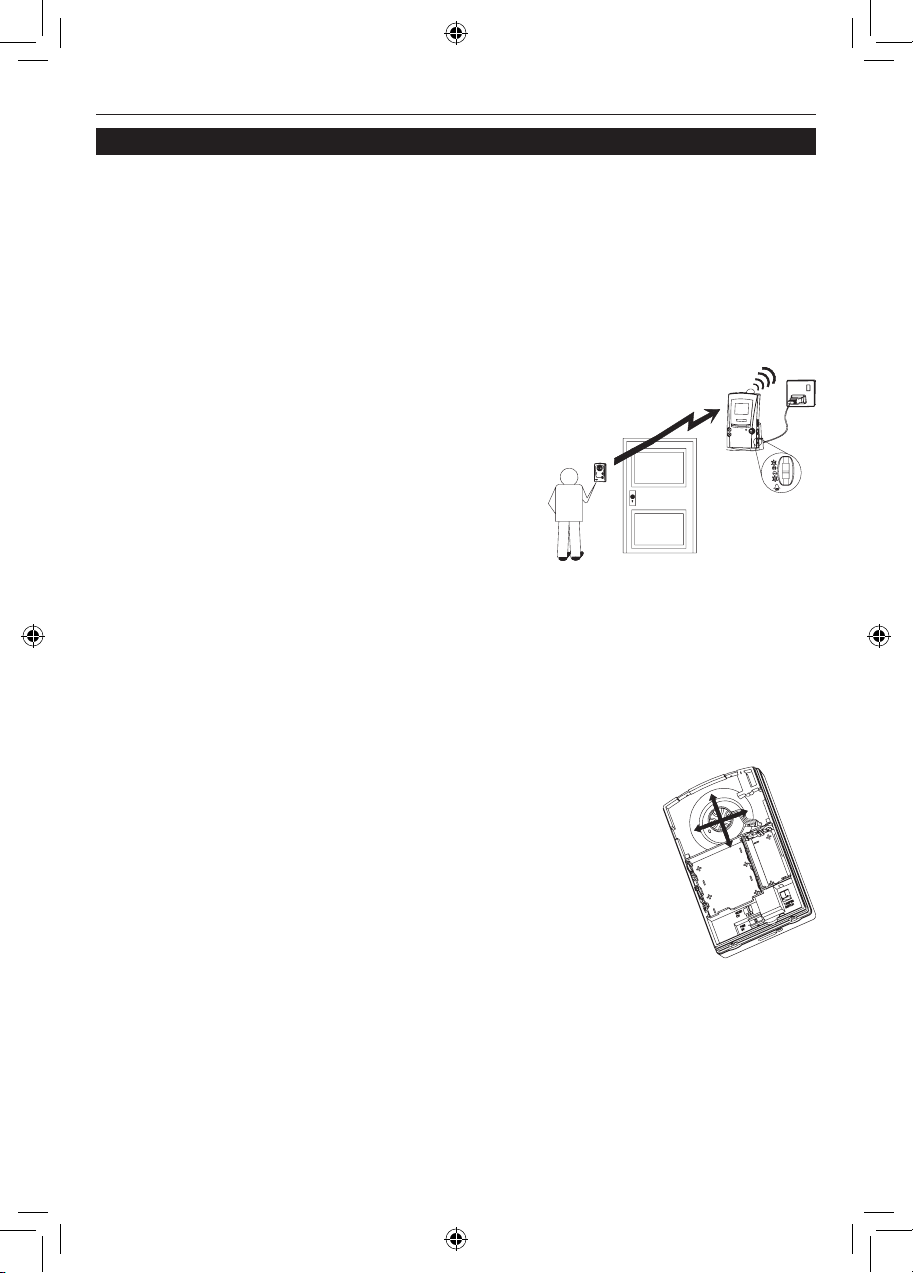
VISIOCAM
41 69-2108EFS—01
Instalación de la cámara de la puerta
Ubicación del receptor
El receptor deberá ubicarse dentro del alcance de la cámara de la puerta (es decir a
menos de 30 m en un edificio promedio).
Pruebe el sistema
Para lograr un funcionamiento confiable, recomendamos que tanto la cámara de la
puerta como el receptor se activen en las ubicaciones finales, para verificar que el
receptor tenga una buena señal procedente de la
cámara de la puerta.
Para probar el sistema, pida a alguien que sostenga
la cámara de la puerta contra la pared en la posición
de montaje que se haya seleccionado y presione el
botón de llamada, mientras usted verifica la recepción de la unidad receptora.
Si la calidad de la imagen es deficiente o si no hay
respuesta cuando se oprime el botón de llamada,
existen tres posibles razones:
1. Puede que las unidades estén muy separadas (más de 30-40 m en una casa
promedio). Intente de nuevo acercando el receptor.
2. Hay interferencia cercana en el canal de video. Retire la parte posterior de
la cámara de la puerta y cambie el interruptor de canal del video del CH 1,
por ejemplo, al CH 3, Verifique el sistema de nuevo, seleccionando un canal
diferente si el canal 3 no resulta mejor.
Refiérase a la sección de localización y solución de problemas
para más información sobre la disminución de la interferencia.
3. La cámara de la puerta no ha sido programada en el receptor
(refiérase a la página 39).
Regule el ángulo de la cámara
Con la cámara de la puerta en la posición prevista, es posible que
necesite ajustar el lente de la cámara para que cubra el área de
observación deseada.
Abra la parte posterior de la cámara de la puerta y regule el ojo de la cámara desde la
parte trasera del producto. Observe que existe más movimiento disponible en la cámara de arriba/abajo que en la dirección izquierda/derecha.
69-2108EFS_A.indd 41 11/30/2007 1:52:04 PM
Page 44

69-2108EFS—01 42
Instalación y uso
3. Fije la base de la cámara de puerta en su lugar utilizando
los tornillos y los enchufes de pared que se proporcionan.
4. Enganche la cámara de la puerta en la base en su parte
superior primero, luego presione y encájela en su parte
inferior. Verifique que la unidad esté uniformemente
colocada en su lugar para sellar la unidad del daño que
pueda producir la lluvia. Asegúrese de que la banda de
sellado del frente de la cámara permanezca en su lugar.
Inserte los dos tornillos por debajo, y apriételos.
Verifique que la unidad esté trabajando después de la instalación presionando el
botón de llamada, la luz de confirmación debe iluminarse.
Instalación de la cámara de la puerta
Monte la cámara de la puerta
No monte la cámara en ambientes húmedos ya que la humedad o la condensación
afectarán las partes internas.
Una vez que haya probado el sistema en su lugar, monte la cámara
en la pared o puerta como sigue:
1. Retire los dos tornillos que se encuentran debajo de la cámara
de la puerta Desenganche y libere la parte frontal y hálela
apartándola de la base. Observe la flecha TOP (SUPERIOR) en
la base.
PARTE
SUPERIOR
2. Si la monta en la pared, marque la ubicación de los
cuatro agujeros de montaje utilizando la base de la
cámara como plantilla. Taladre utilizando una broca
para mampostería de 6mm. La distancia entre los
agujeros de montaje es 72 mm horizontalmente y 92 mm
verticalmente.
69-2108EFS_A.indd 42 11/30/2007 1:52:05 PM
Page 45

VISIOCAM
43 69-2108EFS—01
Opción de transformador para la cámara de la puerta
Para instalaciones donde el uso es frecuente, un promedio de más de cinco usos por día, la cámara de la puerta
puede alimentarse utilizando un transformador para timbre de 8-10 voltios, 1 amp.
Importante: Un transformador de más alto voltaje podría
dañar la cámara.
Conecte la salida de bajo voltaje del transformador a la cámara de puerta utilizando
un cable adecuado de bajo voltaje tal como un cable para timbre o teléfono. El diámetro máximo recomendado para el cable exterior es 5 mm. La longitud del cable no
debe exceder 30 m (100 pies).
La cámara de puerta posee una entrada de cable con un sello contra agua en la parte
posterior. Para conectar el transformador:
1. Inserte el cable a través de la entrada para cable y conéctelo a los terminales
de alimentación. Deje alrededor de 15 cm (6 in) de cable libre entre la base y el
cuerpo de la cámara de la puerta para acceso de servicio posterior. No coloque
baterías.
2. Fije la cámara de la puerta en su lugar. Verifique que el frente
esté total y uniformemente encajado para sellar la unidad
contra el daño producido por la lluvia.
3. Asegure el cable utilizando sujetadores o tachuelas
según sea necesario.
4. Conecte el otro extremo del cable al secundario
(salida de 8 V) de un transformador de timbre
que no tenga energía. Siga las instrucciones del
transformador cuidadosamente para las conexiones adecuadas.
5. Conecte las terminales eléctricas del transformador al suministro eléctrico
apropiado, siempre activado.
Pruebe la cámara de puerta presionando el botón de llamada: la luz de confirmación
deberá iluminarse.
Nota: Si no ha utilizado la cámara de puerta con baterías en una prueba de ensayo,
deberá programar la cámara de puerta con el receptor siguiendo las instrucciones
“programe la cámara de puerta con el receptor”.
Instalación de la cámara de la puerta
TRANSFORMADOR
8V / 1 A
A
L TRANSFORMADOR
69-2108EFS_A.indd 43 11/30/2007 1:52:05 PM
Page 46

69-2108EFS—01 44
Instalación y uso
Funcionamiento del receptor
Cuando se oprime el botón de llamada en la cámara de puerta, el receptor suena
(siempre que el interruptor de volumen no esté en 0) y la imagen de la cámara aparece durante aproximadamente 30 segundos. Si el visitante presiona el botón de
llamada nuevamente, el tiempo de visualización se ampliará a otros 30 segundos. La
transmisión de video se limita a 30 segundos
para conservar la vida de las baterías de la
cámara y esto no es ajustable.
Cuando las baterías necesiten recarga, no
aparecerá imagen de cámara – únicamente
la campanilla suena (a menos que el nivel de
la batería sea demasiado bajo para que se
produzca el sonido).
Base de carga
Al igual que un teléfono portátil, mantenga el receptor
colocado en la base de carga para lograr un funcionamiento confiable. Dependiendo del uso, el recibidor
debería funcionar durante varios días aunque no esté
en la base de carga. La base de carga puede utilizarse
en una superficie plana o fijarse a la pared utilizando
los tornillos y tomacorrientes de pared. Antes de fijarla en su lugar, verifique que el
receptor obtenga una buena señal en la ubicación donde se planea colocar.
Instalación del receptor
VOLUMEN DEL MIC
[PARA USO FUTURO]
BRILLO DE
LA PANTALLA
VOLUMEN DE
LA CAMPANILLA
Indicador de batería
El indicador funciona como sigue:
Permanece encendido cuando el receptor está en la base de carga y está
totalmente cargado.
Destella una vez por segundo cuando el receptor se está cargando.
Permanece apagado cuando el receptor no se encuentra en la base y las
baterías están bien.
Destella lentamente una vez
cada diez segundos
cuando el receptor no está en la base de carga y
necesita recarga.
Luz intermitente de la campanilla
Destella para indicar una llamada cuando el control de volumen de la campanilla está
en la posición 0 o 2*.
Brillo de la pantalla
Active la cámara de puerta presionando su botón de llamada y ajuste la pantalla del
receptor para obtener la mejor imagen utilizando el interruptor deslizante de cuatro
posiciones. Se recomienda la posición inmediatamente anterior al brillo máximo.
Control de volumen de la campanilla
El nivel de volumen de la campanilla puede fijarse utilizando el interruptor deslizante
más bajo de los tres (refiérase al diagrama anterior). Regule a nivel alto (2), nivel bajo
(1), o apagado (0).
69-2108EFS_A.indd 44 11/30/2007 1:52:06 PM
Page 47

VISIOCAM
45 69-2108EFS—01
Instalación del receptor
Selección de melodía de la campanilla
La melodía del receptor de la campanilla puede cambiarse presionando el botón ‘.’
Las opciones de melodía de la campanilla son las siguientes:
• Timbre de dos notas (tono pre-establecido para la cámara de la puerta)
• Saxofón (Melodía pre-establecida para la segunda cámara de la puerta o
pulsador de timbre)
• Timbre de una sola nota
• Sonido de toque con los nudillos
El botón ‘ ’ cambia el tono de la campanilla para una segunda cámara de puerta o
pulsador de puerta.
Funcionamiento nocturno
En condiciones de buena luz de día, el receptor muestra una imagen a color. Cuando
exista poca iluminación o en la noche la pantalla automáticamente cambia a blanco
y negro. Los LED infrarrojos iluminan al visitante, de modo que puedan verse en el
receptor incluso cuando están rodeados de una oscuridad total.
Indicación de batería baja de la cámara
Cuando las baterías de la cámara de la puerta están con poca carga, el receptor lo
indica con un tono doble de advertencia que sigue a la campanilla cuando un visitante
presiona el botón de llamada. Cambie las baterías de la cámara de la puerta en el lapso
de una semana después de recibir la alerta de batería baja.
Tono de alerta por detección de intento de manipulación
Si alguien intenta retirar la cámara de la puerta desatornillando los tornillos, se dispara el tono de alerta por intento de manipulación, el cual permanece audible durante
30 segundos. Revise el exterior inmediatamente.
Presione cualquier botón al frente del receptor para detener el tono de alerta. El interruptor de volumen de la campanilla no afecta el tono de alerta.
Nota: El tono de alerta también se dispara cuando retira la tapa para reemplazar las
baterías en la cámara de la puerta.
Volumen del MIC
[Para uso futuro] El control superior del costado (ver diagrama) controlará el volumen
producido por un micrófono. Regule para lograr el nivel óptimo de audición.
Botón de escaneo
Cuando se utiliza en un sistema de cámaras múltiples, este botón escanea a través
de las imágenes disponibles.
Privacidad
Recuerde que este producto utiliza ondas de comunicación audiovisuales y que la
señal de video de 30 segundos de duración procedente de la(s) cámara(s) de la puerta pueden ser captadas por aparatos receptores de video de 2.4GHz en el área.
69-2108EFS_A.indd 45 11/30/2007 1:52:06 PM
Page 48

69-2108EFS—01 46
Instalación y uso
Sensor de movimiento
El sensor PIR (‘Infrarojo pasivo’) activa la cámara de la puerta automáticamente. El
receptor produce un sonido “metálico” y muestra la imagen de la cámara de la puerta
durante aproximadamente 30 segundos.
En caso de no necesitar el sensor de movimiento, puede desactivarlo.
Para desconectar el sensor de movimiento, presione y sostenga el botón de llamada
de la cámara durante más de diez segundos. El indicador de confirmación destella
rápidamente para confirmar que el sensor de movimiento está desactivado.
Para activar nuevamente el sensor de movimiento, presione y sostenga el botón de
llamada durante más de diez segundos; el indicador de confirmación permanece
encendido por dos segundos para confirmar.
Nota: La pérdida de energía de la cámara o el cambio de las baterías restablecerá
nuevamente el sensor a su estado activo.
Cámara de la puerta
69-2108EFS_A.indd 46 11/30/2007 1:52:06 PM
Page 49

VISIOCAM
47 69-2108EFS—01
Ampliación del sistema
Hay muchas formas de ampliar su sistema de entrada: puede conectar el sistema a
un televisor o añadir más cámaras, por ejemplo.
Conexión de televisión
Puede conectar el receptor a un televisor por medio del accesorio conductor AV que
se suministra. Conecte el enchufe de estéreo a la unidad receptora de la Visiocam y
enchufe el RCA amarillo a la entrada AV del televisor. Coloque el canal del televisor
al canal AV pre-establecido para dicha entrada RCA (refiérase a las instrucciones del
televisor.)
Cuando se active la cámara de la puerta, el receptor de la Visiocam sonará y el televisor mostrará la imagen del visitante.
Nota: El televisor debe colocarse en el canal pre-establecido manualmente para que
muestre la imagen. La función automática de cambio no está disponible.
Adición de un pulsador de puerta
El receptor responderá a un pulsador de puerta Visiocam. Para programar un pulsador de puerta en el receptor:
1. Presione y sostenga el botón ‘ ’ durante aproximadamente cinco segundos
hasta que el receptor emita tres tonos.
2. Presione el botón pulsador de la puerta hasta que suene el receptor.
Nota: El receptor de video no responde a un pulsador de puerta mientras la pantalla
de video esté activa.
Cámaras de la puerta adicionales
El receptor responderá hasta con cuatro cámaras de puerta.
Cada cámara deberá colocarse en un canal de video diferente (1-4) y estar program-
ada en el receptor. Refiérase a las instrucciones que se proporcionan con la unidad
adicional o vea “Para reprogramar o reiniciar el receptor”, en esta sección.
Para reprogramar o reiniciar el receptor
A. Para añadir otra cámara de la puerta, la unidad CCTV o el pulsador del timbre:
Presione y sostenga el botón ‘ ’ durante más de cinco segundos, la unidad emitirá
tres tonos y entrará en la modalidad de programación durante aproximadamente dos
minutos.
Durante los dos minutos de tiempo de programación, presione el botón de llamada o
el botón en la unidad nueva para programarlo. La unidad deberá estar a una distancia
de 10-20 m del receptor para lograr una programación confiable.
B. Para eliminar toda la información programada, por ejemplo cuando cambie una
cámara de la puerta:
Presione y sostenga los botones ‘ ’ y ‘ ’ durante cinco segundos para eliminar la
información programada e ingresar a la modalidad de programación. Escuchará los
sonidos de campanilla disponibles.
Siga la secuencia de programación bajo Preparación del Receptor.
69-2108EFS_A.indd 47 11/30/2007 1:52:06 PM
Page 50

69-2108EFS—01 48
Instalación y uso
CUIDADO Y MANTENIMIENTO
• Las huellas digitales o el sucio en el lente de la cámara pueden causar una
imagen poco nítida o borrosa. Ocasionalmente utilice un paño suave y húmedo
para limpiar la superficie. No utilice productos de limpieza. El exceso de limpieza
o efectuarla con demasiada frecuencia rayará la superficie y enturbiará la
imagen.
• Mantenga el receptor y la base de carga alejada de la lluvia, líquidos o del riesgo
de derrame de líquidos.
• No coloque aros u otros objetos de metal sobre la clavija en la unidad de carga
– ¡se tornarán calientes al tacto!
• No permita que la lluvia o la humedad queden atrapadas dentro de la cámara de
la puerta ya que podría dañar las partes internas.
• Evite cambiar las baterías de la cámara cuando llueva.
• No desmonte los productos; contienen componentes de precisión en su interior
que pueden dañarse fácilmente.
• Evite que las unidades caigan al suelo o que reciban golpes fuertes.
• Utilice únicamente los componentes de suministro eléctrico que se incluyen o
que se recomiendan.
• No utilice ni almacene ninguna unidad en áreas con polvo o suciedad.
CAMBIO DE LAS BATERÍAS DEL RECEPTOR
El uso constante disminuirá eventualmente la capacidad
de las baterías recargables, así como la vida del receptor
cuando está fuera de la base de carga. Cambie las baterías
desatornillando el único tornillo de la cubierta de la batería
en la parte inferior trasera del receptor. Retire las baterías viejas y reemplácelas con tres baterías NiMh tipo
AA con una capacidad mínima de 1200mAH. Siga los
símbolos de orientación de las baterías en el compartimiento de las baterías. Vuelva a colocar la cubierta de
las baterías y el tornillo.
Mantenimiento y uso
2
1
69-2108EFS_A.indd 48 11/30/2007 1:52:07 PM
Page 51

VISIOCAM
49 69-2108EFS—01
Localización y solución de problemas
El sistema no funciona…
• Verifique que la cámara de la puerta tenga energía, refiérase a la información que
se encuentra más abajo
• Verifique que la cámara de la puerta tenga energía, refiérase a la información que
se encuentra más abajo
• Acerque el receptor a la cámara de la puerta para que reciba una mejor señal.
• Si es nuevo, verifique que la cámara esté programada al receptor – refiérase a la
“Preparación de la Pre-instalación” en la página 3.
La cámara de la puerta carece de energía…
Esto se evidencia cuando la luz roja de confirmación del frente no se enciende al presionar el botón de llamada. Compruebe;
• Todas las baterías están colocadas en la dirección correcta
• Las baterías son nuevas y del tipo alcalino
• Si el transformador brinda la energía, el transformador está conectado a la red de
electricidad y encendido
• El cable que conecta el transformador no tiene daño
• Los dos cables en el cable de conexión del transformador están haciendo contacto
con los terminales en la unidad y en el transformador.
El receptor carece de electricidad…
• Las baterías están descargadas. Coloque el receptor en la unidad de carga durante
un mínimo de 12 horas para recargar completamente las baterías. El indicador
de batería del receptor destellará una vez por segundo para indicar carga y
permanecerá encendido cuando el receptor esté completamente cargado.
El receptor tiene únicamente la imagen en blanco y negro…
• El nivel de luz en la cámara de la puerta es muy bajo
• El sensor de luz bajo la cámara de la puerta está cubierto, está demasiado cerca de
un objeto adyacente o está orientado hacia una superficie muy oscura.
La señal es pobre o hay interferencia…
• El receptor está en una señal de “punto muerto”. Rote o mueva el receptor 50 cm e
inténtelo de nuevo. Las personas que caminen cerca del receptor también pueden
afectar la calidad de la recepción.
• Compruebe que el receptor esté en el área de alcance de la cámara de la puerta,
aproximadamente a 30 metros en un edificio promedio. Acerque el receptor para
ver si la imagen mejora. Si esto no mejora la imagen entonces hay interferencia
cercana en el canal de video. Abra la cámara de la puerta y cambie el interruptor
del canal de video del 1 al 3, por ejemplo.
• Si hay más de un transmisor de video (cámara de puerta u otros), cada unidad
deberá tener su interruptor de canal de video colocado en un canal diferente.
• Puede que esté utilizándose un horno microondas en el trayecto entre la cámara de
la puerta y el receptor. Mueva el horno de microondas o apáguelo.
• Las computadoras y otro equipo de IT pueden irradiar señales y afectar la calidad
del video. Si este parece ser el problema, mueva el receptor (al menos a un metro)
de las unidades.
69-2108EFS_A.indd 49 11/30/2007 1:52:07 PM
Page 52

69-2108EFS—01 50
Instalación y uso
El receptor suena, seguido de dos tonos…
Esto indica carga baja en la batería de la cámara de la puerta. Cambie las baterías de
la cámara de la puerta.
Un doble tono suena durante 30 segundos…
Esta es una alerta que se origina en el interruptor contra manipulación indicando
que alguien está tratando de desatornillar y retirar la cámara de la puerta. Échele un
vistazo de inmediato.
El tono puede dispararse si los tornillos que fijan el frente de la cámara de la puerta a
su parte trasera no están totalmente atornillados en su lugar.
Presione cualquier botón del receptor para apagar el tono de alerta.
El receptor se enciende aleatoriamente…
Esto se debe probablemente a que el sensor de movimiento recoge la señal de los
transeúntes, carros o fuentes de calor en movimiento.
Apague el sensor PIR (refiérase a la sección “CÁMARA DE LA PUERTA”), bloquee el
movimiento no deseado o reubique la cámara de la puerta.
La campanilla suena pero la imagen aparece únicamente durante pocos
segundos…
• La señal de video ha sido interrumpida. Presione el botón Scan para recaptar la
señal de video, mueva el receptor a otra posición cercana.
• Si esto ocurre regularmente, ubique el receptor más cercano a la unidad de la
puerta, o coloque el receptor en una posición más alta. Generalmente el receptor
recibirá una señal más fuerte cuando está ubicado en una repisa y una señal más
débil si está cerca del suelo.
• La batería tiene poca carga. Coloque el receptor en el cargador durante al menos
cuatro horas para recargar las baterías.
Troubleshooting
69-2108EFS_A.indd 50 11/30/2007 1:52:07 PM
Page 53

VISIOCAM
51 69-2108EFS—01
Especificaciones
Cámara de la puerta Receptor
Requerimientos de electricidad 110 V AC ±10% por medio del
cargador
Tipo de batería 6 Baterías alcalinas AA 3 baterías NiMH tamaño AA,
mínimo 1200mAh
Vida operativa de la batería por lo general un año* por lo general 3 días partiendo de
carga total*
Alcance del sensor de movimiento 4 m en promedio (sensibilidad
cuando está fijada)
N/A
Energía opcional a través de transformador de tim-
bre 8V a 10V 1A** o alimentación
8–12V AC o DC
N/A
Número máximo de transmisores
(video o pulsador de puerta) programables por receptor
N/A 4 (1, 2 con tono de campanilla
seleccionable; 3, 4 con tono de
campanilla fijo)
Salida del sonido N/A 80dBA/1m (posición 2)
Frecuencia de operación 433MHz y 2.4GHz 433MHz y 2.4GHz
Nivel de salida RF <1mW N/A
Tipo de antena (integrada) omnidireccional omnidireccional
Tipo de cámara Sensor CMOS
Solución efectiva 628 x 582 pixels TFT LCD pantalla de color ver-
dadero
Video estándar NTSC NTSC
Canales de video configurables 4 4, con autodetección
Salida de video N/A 1Vpp 75W
Cambio de Color a B/N Aprox. 100 lux de brillo
Temperatura de funcionamiento –10°C to 40°C
14°F to 104°F
0°C to 40°C
32°F to 104°F
Peso 340 g (13 oz.) (sin baterías) 13 oz. (340 g) (con baterías)
Tamaño H x W x D 160 x 97 x 49 mm
(6.3 x 3.8 x 1.9 in.)
160 x 86 x 47 mm
(6.3 x 3.4 x 1.8 in.)
A prueba de lluvia Pasa la prueba de lluvia UL1598 N/A
* Basado en 3 llamadas por día en un clima moderado. El uso más frecuente, o funcionamiento en ambiente a
baja temperatura (–10 to 5°C) disminuirá la vida de la batería.
69-2108EFS_A.indd 51 11/30/2007 1:52:08 PM
Page 54

69-2108EFS—01 52
Instalación y uso
DECLARACION
Honeywell por la presente declara que este producto cumple con la Parte 15 de las regulaciones FCC y las normas industriales de Canadá. El funcionamiento de este dispositivo está
sujeto a las siguientes dos condiciones:
(1) Este dispositivo no debe causar interferencia perjudicial y (2) Este dispositivo deberá
aceptar cualquier interferencia que se reciba, incluyendo la interferencia que pudiese causar
el funcionamiento no deseado. Precaución: Los cambios o modificaciones que no hayan sido
expresamente aprobados por la parte responsable del acatamiento a las regulaciones podrían
anular la autoridad del usuario para operar el equipo.
La base de carga cumple con las normas relevantes de los requerimientos de seguridad CUL
y UL60065.
GARANTÍA
Honeywell garantiza este producto por el lapso de 1 año a partir de la fecha de compra. La
prueba de compra es necesaria; esto no afecta sus derechos legales. Si necesita mayor información sobre su producto, llame a la línea de ayuda de Honeywell al 1-800-468-1502.
DESECHO Y RECICLAJE
Las baterías y los desechos procedentes de productos eléctricos no deberán colocarse con los
residuos domésticos. Por favor recicle donde existan tales instalaciones. Verifique con las
autoridades locales o el distribuidor la disponibilidad del servicio de reciclaje.
69-2108EFS_A.indd 52 11/30/2007 1:52:08 PM
Page 55

VISIOCAM
53 69-2108EFS—01
69-2108EFS_A.indd 53 11/30/2007 1:52:08 PM
Page 56

Honeywell International Inc.
ACS, Environmental and Combustion Controls
1985 Douglas Drive, Golden Valley, MN 55422
www.honeywell.com
Impreso en los EE. UU., en papel
reciclado que contiene por lo menos
un 10% de fibras de papel reciclable.
Marca registrada de los EE. UU.
© 2007, Honeywell International Inc.
69-2108EFS—01 M.S. 11-07
69-2108EFS_A.indd 54 11/30/2007 1:52:08 PM
 Loading...