

Page 1
M896
69-1089B-1
Damper Actuator
INSTALLATION INSTRUCTIONS
APPLICA TION
The M896 Damper Actuator is a 24 Vac motor with an
external shaft for coupling. Powered rotation is counterclockwise (ccw), with a maximum rotation of 110°. The
actuator is designed as a replacement actuator for the
D892 and D896 Automatic Vent Dampers or as the
original actuator on similar OEM dampers. Maximum OEM
damper operating torque cannot exceed ten in.-oz.
OPERATION
On a call for heat, the actuator automatically opens the
damper and the furnace or boiler begins its ignition cycle.
When the heating cycle ends, the burner turns off and the
actuator automatically closes the damper. Heating system
efficiency is increased because the closed damper
reduces the loss of residual appliance heat and heated
room air through the draft diverter.
INST ALLATION
When Installing this Product…
1. Read these instructions carefully. Failure to follow
them could cause a hazardous condition.
2. Check the ratings given in the instructions and on
the product to make sure the product is suitable for
your application.
3. Installer must be a trained experienced service
technician.
4. Install the M896 Damper Actuator as a replacement
only on AGA/CGA-approved damper systems.
5. After installation is complete, check out actuator
operation as provided in the Checkout section.
W ARNING
Severe illness or death possible.
Prevent dangerous buildup of
carbon monoxide.
Be sure damper used with M896 has a return
spring that opens the damper if the coupler fails.
CA UTION
Electrical shock or equipment
damage possible.
1. Disconnect power supply.
2. Do not negate the action of any existing safety
or operational control.
3. Make sure that the damper return spring is
operational prior to installing the actuator.
4. Label all wires prior to disconnecting when
servicing controls. Wiring errors can cause
improper and dangerous operation.
To Install the M896 Damper Actuator:
1. Remove the existing actuator.
2. Make sure the damper return spring is operational.
(The damper return spring must open the damper
when the actuator coupling is removed to prevent a
dangerous buildup of carbon monoxide.)
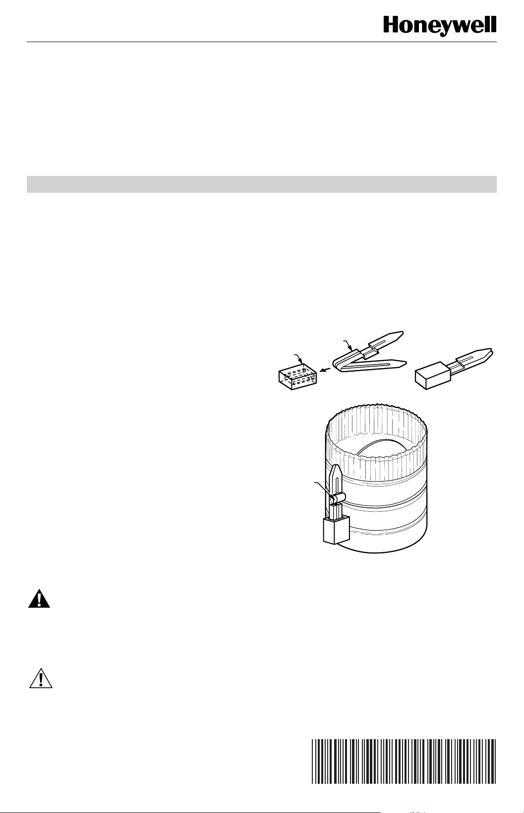
3. Locate the arrow coupler and keeper clip
(see Fig. 1).
ARROW
KEEPER
CLIP
4. Slip keeper clip over arrow coupler as shown in Fig.
5. Install the arrow coupler in the slot on the damper
6. Align the slot on the actuator shaft with the arrow
7. Attach the actuator to the damper bracket using the
8. Remove the keeper clip from the arrow coupler.
9. Connect the Molex plug to the M896 Harness Cable
COUPLER
AB
DAMPER
SHAFT
Fig. 1. Installing arrow coupler on damper
1. This compresses the arrow coupler.
shaft with the arrow pointing up.
coupler and attach the actuator to the damper.
See Fig. 2. (If the actuator output shaft is not
properly aligned with the arrow coupler, manually
turn the motor knob with a screwdriver to align the
actuator shaft.)
screws removed in step 1.
Connector.
shaft using keeper clip.
M3949
Copyright © 1997 Honeywell Inc. • All Rights Reserved
X-XX UL
Page 2
M896 DAMPER ACTUATOR
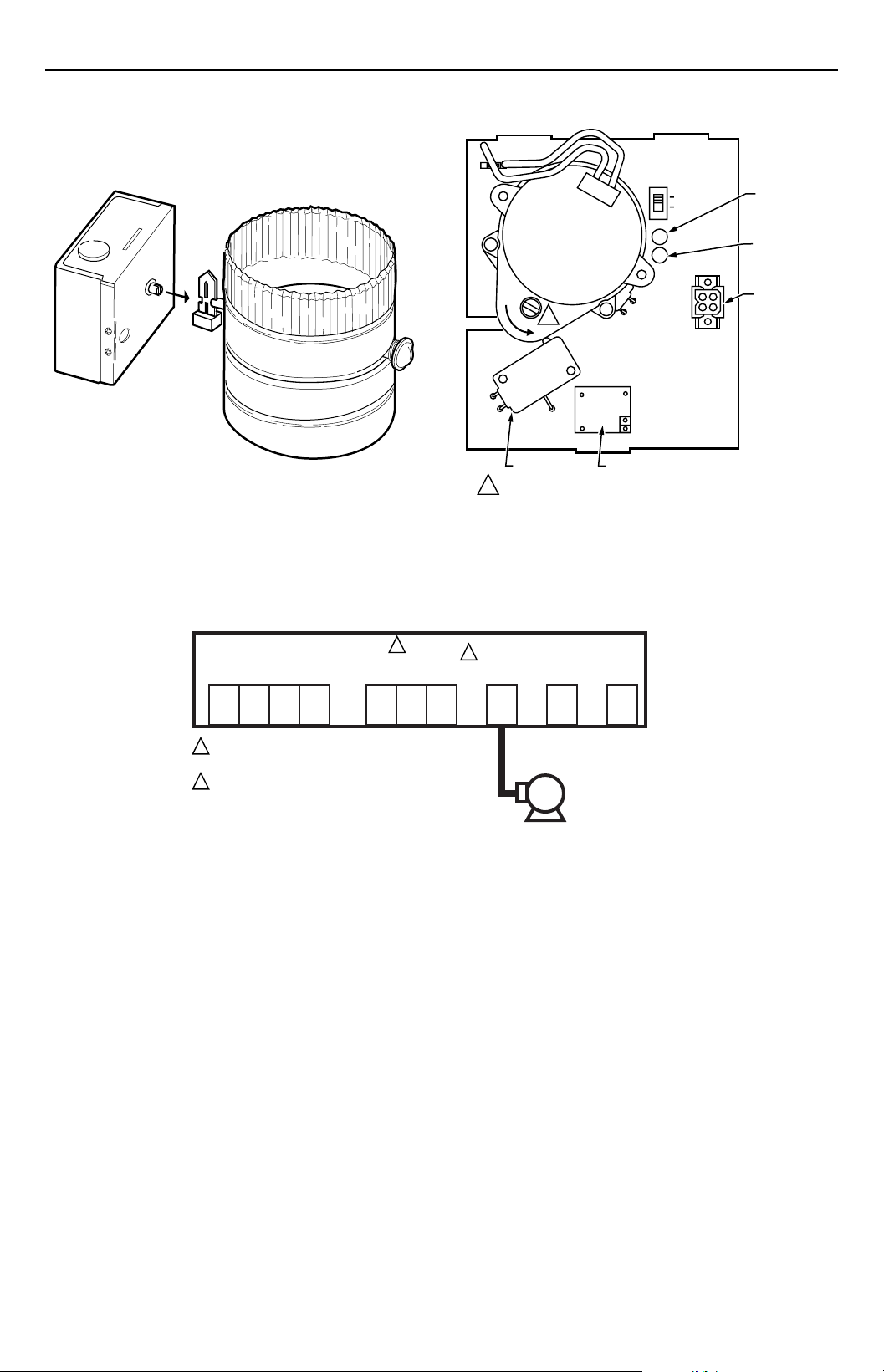
Other wiring connections are necessary. Follow the
furnace or boiler manufacturer wiring instructions, or
refer to Fig. 3 through 5.
DAMPER BRACKET
REMOVED FOR CLARITY
Fig. 2. Installing M896 Damper Actuator on damper.
M3947
M896
SERVICE
SWITCH
NORM
SERV
1
S3 SWITCH
1
USE STANDARD SCREWDRIVER TO MANUALLY OPEN AND
CLOSE VENT DAMPER. PLACE SCREWDRIVER IN SLOTTED
KNOB AND ROTATE COUNTERCLOCKWISE UNTIL
BOTH LEDS TURN ON.
RELAY 1K
Fig 3. M896 with cover removed.
IGNITION GAS
PWR LED
CALL FOR
HEAT LED
HARNESS
CABLE
CONNECTOR
M11367
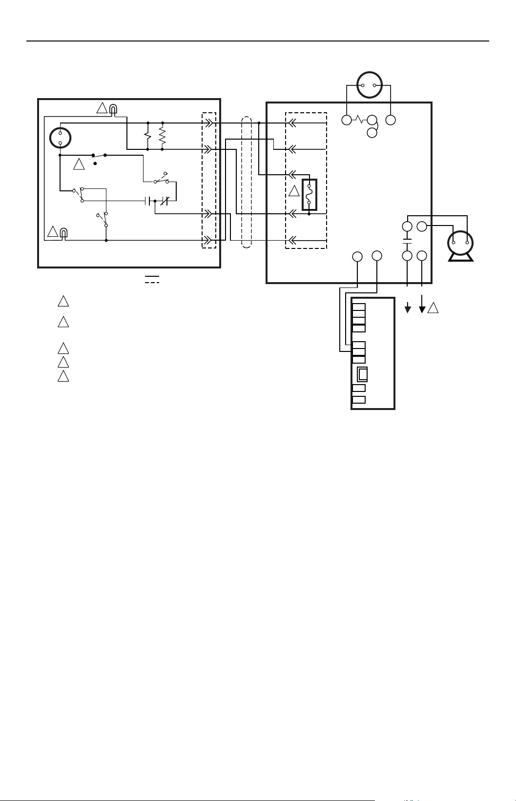
S8600F, H, M; S8610F,H
1
GND
MV MV/PV PV
POWER SUPPLY. PROVIDE DISCONNECT MEANS
1
AND OVERLOAD PROTECTION AS REQUIRED.
REMOVE PLUG ONLY IF USING VENT DAMPER. FUSE
2
BLOWS ON STARTUP WHEN PLUG IS REMOVED;
THEN MODULE OPERATES ONLY WHEN VENT
DAMPER IS CONNECTED.
(BURNER)
24V
GND
24V SPARK
2
VENT
DAMPER
PLUG
WIRING
HARNESS
SENSETH-W
M896/D896
VENT
DAMPER
M11369
Fig. 4. Wiring diagram for M896 (D896) connection to L8148E1166 using wiring harness with two Molex plugs.
69-1089B–1
2
Page 3
M896/D896
LED 2
4
N.O.
S2
C
K1
C
N.O.
S3
K1
DAMPER OPEN
DAMPER CLOSED
MOTOR
NORMAL
S4
5
SERVICE
N.O.
N.C.
S1
C
N.C.
LED 1
3
POLARIZED 4-PRONG MALE MOLEX PLUG AND
4-PRONG FEMALE MATING PLUG ON CABLE
SWITCHES AS SHOWN: S1,S2,S3
1
POWER SUPPLY. PROVIDE DISCONNECT MEANS AND OVERLOAD
PROTECTION AS REQUIRED.
AFTER M896/D896 VENT DAMPER IS PLUGGED TO L8148E1166, FUSE
2
BLOWS WHEN THERMOSTAT FIRST CLOSES. AFTER FUSE BLOWS,
L8148E1166 OPERATES ONLY WHEN VENT DAMPER IS CONNECTED.
3
LED 1 LIGHTS WHEN DAMPER IS OPEN.
4
LED 2 LIGHTS WITH CALL FOR HEAT.
5
SERVICE SWITCH. THE NORMAL SWITCH SETTING IS NORM. IF THE
SWITCH IS MOVED TO THE SERV POSITION, THE DAMPER REMAINS OPEN.
R1, R2, R3
250 OHMS
N.C.
4
2
1
3
WIRING
HARNESS
24 Vac
THERMOSTAT
4
2
3
FUSE
2
5
1
6-PRONG FEMALE MOLEX
RECEPTACLE IN L8148E
AND 5-PRONG MALE
MOLEX PLUG ON CABLE
M896 DAMPER ACTUATOR
L8148E1166
TW
1K
B1
Z
24V GND
24V
TV
C2
C1
1K1
L2
L1B2
CIRCULATOR
L1
L2
(HOT)
1
M11368
Fig. 5. Wiring diagram for M896 (D896) connection to S8600/S8610 using wiring harness with two Molex plugs.
SETTINGS
The service switch has both a normal (NORM ) and a
service (SERV) mode.
NORM — M896 opens on a call for heat and closes at
the end of the heating cycle.
SERV — M896 electrically opens after the thermostat
has a call for heat and remains open.
CHECKOUT
Heating
1. Turn off the power supply.
2. If using a thermostat, set the heat anticipator to
0.13A.
3. Set the thermostat or controller to 10°F (6°C) above
the room temperature to call for heat.
4. Check that the M896 Damper Actuator opens the
damper before the gas valve opens and the pilot or
main burner ignites. See Fig. 6.
NOTE: If a boiler gas control is sequenced by the
Aquastat® Controller, be sure that the
actuator opens the damper prior to the
opening of the gas control.
5. Turn the thermostat or controller 10°F (6°C) below
the room temperature. Check that the M896 Damper
Actuator closes the damper.
6. Cycle the heating system three times using the
thermostat or controller to assure that the system is
operating safely.
3
69-1089B–1
Page 4

M896 DAMPER ACTUATOR
THE AIR DUCT IS CLOSED WHEN THE
INDICATOR POINTS PERPENDICULAR TO
THE DIRECTION OF THE AIR DUCT
M3943
Fig. 6. Determining damper position.
Cooling
CA UTION
Damage to air conditioner condenser possible.
Do not operate cooling if outdoor temperature is
below 50°F (10°C).
1. Set the thermostat or controller to cool. Move the
setpoint 10°F (6°C) below the room temperature.
2. Make sure the cooling system operates.
3. Check that the damper remains in the closed
position. See Fig. 6.
4. Return the thermostat or controller to the desired
settings.
THE AIR DUCT IS OPEN WHEN
THE INDICATOR POINTS IN THE
DIRECTION OF THE AIR DUCT
NOTE: If there is a power failure, the damper remains
Set the thermostat or controller below the room temperature. Wait one minute and turn the thermostat or controller
above the room temperature to call for heat. If the system
does not start, leave the thermostat or controller calling for
heat and troubleshoot the M896/D896 as follows:
exactly where it is at the moment of failure (open,
closed, or somewhere between). When power is
restored, the damper opens if the thermostat is
calling for heat or closes if the thermostat is not
calling for heat.
NOTE TO INSTALLER:
Explain to the homeowner that a yearly inspection by a trained, experienced service technician
is necessary for safe, efficient operation of the
vent damper and heating system. The homeowner should check for deterioration from
corrosion or other sources between service
technician calls.
TROUBLESHOOTING
W ARNING
Fire or explosion hazard.
Can cause property damage,
severe injury or death.
Explosion or carbon monoxide poisoning possible.
Never apply a jumper across or short gas control
terminals or wires. This can force the damper to
remain closed and cause an explosion.
Home and Building Control
Honeywell Inc.
Honeywell Plaza
P.O. Box 524
Minneapolis, MN 55408-0524
Home and Building Control
Honeywell Limited-Honeywell Limitée
155 Gordon Baker Road
North York, Ontario
M2H 3N7
Use a voltmeter and check for 24 Vac at the S8600,
S8610, L8148E, gas valve or other control.
1. If no voltage, check the transformer, limit controller
and wiring.
2. If 24 Vac is present, and the D896 is open, refer to
the furnace or boiler manufacturer instructions.
3. If D896 is closed:
a. Place the service switch in the SERV position.
See Fig. 4.
b. Manually open the damper using a standard
screwdriver. Place screwdriver in slotted knob
(see Fig. 4) and rotate counterclockwise until
both LEDs turn on.
c. If system does not light with damper in the
fully open position, replace the M896.
Helping You Control Your World
®
69-1089B–1
69-1089B–1 G.H. 9-97 Printed in U.S.A.
4
Page 5

Actionneur de registre
69-1089B-1
M896
INSTALLATION INSTRUCTIONS
APPLICA TION
Le moteur de registre M896 est un moteur 24 V c.a. avec
arbre extérieur servant à l’accouplement. La rotation
motorisée a lieu dans le sens antihoraire sur une course
de 110 degrés. L’actionneur est conçu comme pièce de
rechange pour les registres d’aération automatiques D896
ou comme pièce d’origine de registres similaires. Le
couple de service maximal du registre du fabricant ne
peut dépasser 10 po-oz.
FONCTIONNEMENT
Lors d’un appel de chaleur, l’actionneur ouvre
automatiquement le registre, et le générateur d’air chaud
ou la chaudière commence son cycle d’allumage. Lorsque
le cycle de chauffage prend fin, le brûleur s’éteint et
l’actionneur referme automatiquement le registre.
L’efficacité du système de chauffage s’accroît car la
fermeture du registre réduit la perte de chaleur résiduelle
et de chaleur ambiante par l’ouverture du coupe tirage.
INST ALLATION
Avant d’installer ce produit…
1. Lire les instructions attentivement. Le fait de ne pas
les suivre risque de constituer un danger.
2. Vérifier les caractéristiques spécifiées dans les
instructions et indiquées sur le produit, et s’assurer
que celui-ci correspond à l’application prévue.
3. L’installateur doit être un technicien d’expérience
ayant reçu une formation pertinente.
4. Installer l’actionneur de registre M896 comme pièce
de rechange uniquement dans les systèmes à
registre approuvés par l’AGA/CGA.
5. Une fois l’installation terminée, vérifier le
fonctionnement du produit comme l’indique la
section Vérification.
MISE EN GARDE
Risque de choc électrique ou de dommage
au matériel.
1. Couper l’alimentation.
2. Ne pas empêcher le fonctionnement de tout
dispositif de commande ou de sécurité déjà
en place.
3. S’assurer que le ressort de rappel du registre
fonctionne comme il se doit avant d’installer
l’actionneur.
4. Étiqueter tous les fils avant de les débrancher
au moment de l’entretien des régulateurs. Les
erreurs de raccordement peuvent empêcher
l’actionneur de bien fonctionner et provoquer
un danger.
Pour installer l’actionneur de registre M896 :
1. Retirer l’actionneur existant.
2. S’assurer que le ressort de rappel du registre
fonctionne bien. (Le ressort de rappel du registre
doit faire ouvrir le registre lorsque l’accouplement
de l’actionneur est enlevé afin d’empêcher
l’accumulation dangereuse de monoxyde
de carbone.)
3. Repérer l’accouplement en flèche et la goupille
(voir Fig. 1 ).
ACCOUPLEMENT
EN FLÈCHE
GOUPILLE
ARBRE DU
REGISTRE
A
B
AVERTISSEMENT
Peut causer des maladies graves et entraîner la
mort. Empêcher l’accumulation dangereuse au
monoxyde de carbone.
S’assurer que le registre employé avec le M896
est muni d’un ressort de rappel qui ouvre le
registre si l’actionneur fait défaut.
Copyright © 1997 Honeywell Inc. • All Rights Reserved
MF3949
Fig. 1. Installation d’un accouplement en flèche sur un
arbre de registre à l’aide d’une goupille.
X-XX UL
Page 6

ACTIONNEUR DE REGISTRE M896
4. Faire glisser la goupille par-dessus l’accouplement
en flèche, comme l’illustre la Fig. 1. Cela a pour
effet de comprimer l’accouplement en flèche.
5. Installer l’accouplement en flèche dans la fente de
l’arbre du registre en faisant pointer la flèche vers
le haut.
6. Placer la fente de l’arbre du registre vis-à-vis
l’accouplement en flèche et fixer l’actionneur au
registre. Voir la Fig. 2. (Si l’arbre qui sort de
l’actionneur n’est pas vis-à-vis l’accouplement en
flèche, faire tourner le bouton du moteur à la main à
l’aide d’un tournevis pour que l’arbre de l’actionneur
soit aligné.
SUPPORT DU REGISTRE
RETIRÉ POUR PLUS DE CLARTÉ
MF3947
Fig. 2. Installation de l’actionneur de registre
M896 sur le registre.
7. Fixer l’actionneur au support du registre à l’aide des
vis retirées à l’étape B.
8. Retirer la goupille de l’accouplement en flèche.
9. Brancher la prise molex au faisceau de fils du M896.
Il faut maintenant effectuer d’autres raccordements. Suivre
les directives du fabricant du générateur d’air chaud ou de
la chaudière, ou consulter les figures 3 à 5.
M896
INTERRUPTEUR
DE SERVICE
NORM
SERV
1
INTERRUPTEUR S3
1
UTILISER UN TOURNEVIS STANDARD POUR OUVRIR ET FERMER
MANUELLEMENT LE REGISTRE D’AÉRATION. INSÉRER LE TOURNEVIS
DANS LE BOUTON FENDU ET FAIRE TOURNER DANS LE SENS
ANTIHORAIRE JUSQU’À CE QUE LES DEUX VOYANTS SOIENT ALLUMÉS.
RELAIS K1
VOYANT
IGNITION
GAS POWER
VOYANT CALL
FOR HEAT
CONNECTEUR
À FAISCEAU
DE FILS
MF11367
Fig. 3. M896 sans couvercle.
S8600F, H, M; S8610F,H
GND
MV MV/PV PV
1
ALIMENTATION. FOURNIR, AU BESOIN, UN DISPOSITIF
DE COUPURE ET UNE PROTECTION CONTRE
LES SURCHARGES.
2
ENLEVER LA PRISE SEULEMENT SI LE REGISTRE
EST UTILISÉ. LE FUSIBLE FONDRA À LA MISE EN
SERVICE; PAR LA SUITE, LE MODULE NE
FONCTIONNERA QUE SI LE REGISTRE
D’AÉRATION EST BRANCHÉ.
(BURNER)
1
24V
GND
24V SPARK
2
VENT
DAMPER
PLUG
FAISCEAU
DE FILS
SENSETH-W
REGISTRE
D’AÉRATION
M896/D896
MF11369
Fig. 4. Schéma de raccordement d’un M896 (D896) au L8148E1166 à l’aide d’un faisceau de fils et
de deux prises molex.
69-1089B-1
2
Page 7

M896/D896
VOYANT 2
4
N.O.
S2
C
K1
N.O.
C
S3
K1
MOTEUR
NORMAL
S4
5
SERVICE
N.O.
N.F.
S1
C
N.F.
VOYANT 1
3
PRISE MOLEX MÂLE À 4 BROCHES POLARISÉES
ET PRISE MOLEX FEMELLE À 4 BROCHES
CORRESPONDANTE SUR LE CÂBLE
1
ALIMENTATION. FOURNIR, AU BESOIN, UN DISPOSITIF DE COUPURE
ET UNE PROTECTION CONTRE LES SURCHARGES.
UNE FOIS LE REGISTRE M896/D896 RACCORDÉ AU L8148E1166, LE FUSIBLE
2
FONDRA LORSQUE LE THERMOSTAT SE REFERMERA POUR LA PREMIÈRE FOIS.
UNE FOIS LE FUSIBLE FONDU, LE L8148E1166 NE FONCTIONNERA QUE SI LE
REGISTRE D’AÉRATION EST BRANCHÉ.
3
LE VOYANT 1 S’ALLUME LORSQUE LE REGISTRE EST OUVERT.
4
LE VOYANT 2 S’ALLUME LORS D’UN APPEL DE CHALEUR.
INTERRUPTEUR DE SERVICE. LA POSITION NORMALE DE CET INTERRUPTEUR
5
EST NORM. SI L’INTERRUPTEUR EST À LA POSITION SERV, LE REGISTRE RESTE OUVERT.
R1, R2, R3
250 OHMS
N.F.
4
2
1
3
FAISCEAU
DE FILS
ACTIONNEUR DE REGISTRE M896
THERMOSTAT
24 V c.a
4
2
3
FUSIBLE
2
5
1
RÉCEPTACLE DE PRISE
MOLEX FEMELLE À 6
BROCHES DANS LE
L8148E ET PRISE MOLEX
MÂLE À 5 BROCHES
SUR LE CÂBLE
TW
1K
B1
24V MISE
24V À LA
TERRE
TV
Z
L8148E1166
C1
1K1
L1B2
L1
(SOUS
TENSION)
C2
L2
CIRCULATEUR
L2
1
MF11368
Fig. 5. Schéma de raccordement d’un M896 (D896) au S8600/S8610 à l’aide d’un faisceau de fils et
de deux prises molex.
RÉGLAGES
L’interrupteur d’entretien comporte la position normale
(NORM) et la position service (SERV).
NORM—Le M896 s’ouvre lors d’une demande de
chaleur et se referme à la fin du cycle de chauffage.
SERV—Le M896 s’ouvre électriquement après un
appel de chaleur du thermostat et reste ouvert.
VÉRIFICATION
Chauffage
1. Couper l’alimentation électrique.
2. Si on utilise un thermostat, régler la résistance
anticipatrice de chaleur à 0,13 A.
3. Régler le thermostat ou le régulateur à 6 °C (10 °F)
au-dessus de la température ambiante pour
provoquer une demande de chaleur.
4. Vérifier si l’actionneur de registre M896 ouvre le
registre avant que la vanne à gaz ne s’ouvre et
que la veilleuse du brûleur principal s’allume. Voir
la Fig. 6.
REMARQUE:
Si la vanne à gaz d’une chaudière est
commandée en séquence par un régulateur
Aquastat®, s ‘assurer que l’actionneur fait
ouvrir le registre ouvre avant l’ouverture de la
vanne à gaz.
5. Remettre le thermostat ou le régulateur à 6 °C
(10 °F) au-dessous de la température ambiante.
Vérifier si l’actionneur de registre M896 referme
le registre.
6. Faire faire au moins trois cycles de chauffage au
système au moyen du thermostat ou du
régulateur et s’assurer que le système fonctionne
en toute sécurité.
3
69-1089B–1
Page 8

ACTIONNEUR DE REGISTRE M896
LA GAINE D’AIR EST FERMÉE LORSQUE LA FLÈCHE POINTE
PERPENDICULAIREMENT AU SENS DE LA GAINE D’AIR.
MF3431
Fig. 6. Comment déterminer la position du registre.
Refroidissement
AVERTISSEMENT
Risque d’endommager le condenseur du
climatiseur.
Ne pas faire fonctionner le système de
refroidissement si la température extérieure est
inférieure à 10 °C (50 °F).
1. Régler le régulateur ou le thermostat est à la
position COOL. Déplacer le curseur à 6 °C (10 °) audessous de la température ambiante.
2. S’assurer que le système de refroidissement
fonctionne.
3. S’assurer que le registre est en position fermée. Voir
la Fig. 6.
4. Remettre le thermostat ou le régulateur au point de
consigne souhaité.
REMARQUE À L’INTENTION DE L’INSTALLATEUR:
Expliquer au propriétaire qu’une inspection
annuelle par un technicien d’expérience ayant
reçu une formation pertinente s’impose pour
des questions de sécurité et pour assurer le
bon fonctionnement du registre d’aération et du
système de chauffage. Le propriétaire devrait
vérifier s’il y a des signes de détérioration
causée par la corrosion ou d’autres causes
entre les visites du technicien.
DÉP ANNAGE
MISE EN GARDE
Risque d’incendie ou d’explosion. Peut causer
des dommages à la propriété, et provoquer des
blessures ou même entraîner la mort.
Risque d’explosion ou d’empoisonnement au
monoxyde de carbone. Ne jamais placer de
cavalier entre les bornes ou les fils du régulateur à
gaz et ne jamais court-circuiter le régulateur à gaz.
Cela pourrait forcer le registre à rester en position
de fermeture et provoquer une explosion.
LA GAINE D’AIR EST OUVERTE LORSQUE LA
FLÈCHE POINTE DANS LA SENS DE LA GAINE D’AIR.
REMARQUE:
Régler le thermostat ou le régulateur au-dessous de la
température ambiante. Attendre une minute et remettre le
thermostat ou le régulateur à un point de consigne
supérieur à la température ambiante pour provoquer une
demande de chaleur. Si le système ne se met pas en
marche, laisser le thermostat ou le régulateur au même
réglage (pour provoquer une demande de chaleur) et
vérifier le fonctionnement du M896/D896 comme suit :
Au moyen d’un voltmètre, vérifier s’il y a du courant 24 V
c.a. au S8600, S8610 ou L8148E, à la vanne à gaz ou
autre régulateur.
En cas de panne de courant, le registre restera
exactement à la position où il se trouve au
moment de la panne (ouvert, fermé ou entre les
deux). Lorsque le courant sera rétabli, le
registre ouvrira si le thermostat demande de la
chaleur ou se refermera si le thermostat ne
demande pas de chaleur.
1. S’il n’y a pas de courant, vérifier le transformateur, le
limiteur et le câblage.
2. S’il y a du courant 24 V c.a et que le registre D896
est ouvert, consulter les instructions du fabricant de
la chaudière ou du générateur d’air chaud.
3. Si le D896 est fermé:
a. Placer l’interrupteur d’entretien à la position
SERV. Voir la Fig. 4.
b. Ouvrir manuellement le registre à l’aide d’un
tournevis. Insérer le tournevis dans le bouton
fendu (voir la Fig. 4) et tourner dans le sens
antihoraire jusqu’à ce que les deux voyants
s’allument.
c. Si le système ne s’allume pas et que le
registre est en position d’ouverture complète,
remplacer le M896.
Home and Building Control
Honeywell Inc.
Honeywell Plaza
P.O. Box 524
Minneapolis, MN 55408-0524
69-1089B-1
69-1089B–1 G.H. 9-97 Imprimé aux États-Unis
Home and Building Control
Honeywell Limited-Honeywell Limitée
155 Gordon Baker Road
North York, Ontario
M2H 3N7
Pour la maîtriste de votre univers
4
®
 Loading...