

Page 1

M7410G
LINEAR VALVE ACTUATOR
WITH LON CAPABILITIES AND OPTIONAL PI-CONTROL
PRODUCT DATA
CONTENTS
APPLICATION............................................................ 2
FEATURES................................................................. 2
DEVICE SPECIFICATIONS ....................................... 3
OPERATION............................................................... 3
VERSIONS.................................................................. 3
PLUG-INS, XIF FILES AND DRF FILES.................... 3
Plug-Ins.................................................................... 4
XIF Files................................................................... 4
DRF- Files................................................................ 4
MOUNTING POSITION ..............................................4
MOUNTING................................................................. 4
ELECTRIC WIRING.................................................... 4
Wiring Colors ...........................................................5
Digital Input .............................................................. 5
COMMISSIONING ADVICE .......................................5
SERVICE LEDS AND SERVICE PIN DESCRIPTION5
Priorities of the different possible situations .......17
Factory Settings ..................................................17
Behaviour of the Controller after Power On /
Reset / Offline-Online..........................................17
Node Object (actuators with PI-controller only) .....18
LNS PLUG-IN DESCRIPTION..................................19
Actuator Object.......................................................19
Diagnostic and Test ............................................19
Configuration Screen ..........................................20
PI-Controller Object................................................24
Monitoring ...........................................................24
Configuration of PI-Controller .............................26
APPLICATION EXAMPLE FOR M7410G1032 /
M7410G1040 / M7410G1057....................................27
DIMENSIONS (MM).................................................... 6
LONMARK NETWORK INTERFACE ........................ 7
Actuator object ......................................................... 7
Description of used SNVTs* and SCPTs** .......... 8
Selection of digital input usage........................... 11
Watchdog for the supervision of the actuation
signal ..................................................................11
Factory settings ..................................................11
Behavior of the Actuator after Power-on /
Reset / Offline-Online ......................................... 11
Interruption of the synchronization ..................... 11
What happens at Offline-Online Mode Changes 12
Controller Object (actuators with PI-controller only)13
Description of used SNVTs and SCPTs............. 14
Relation between nviOccupancy, nciSetpoint,
nviSetpoint and nviSetPtOffset........................... 15
Echelon, Lon, LonMark, LonWorks, and the LonMark Logo
are Registered Trademarks of Echelon Corporation
Copyright © 2002 Honeywell Inc.
All Rights Reserved. EN0B-0235 GE51R0802
Page 2
PRODUCT DATA
FEATURES
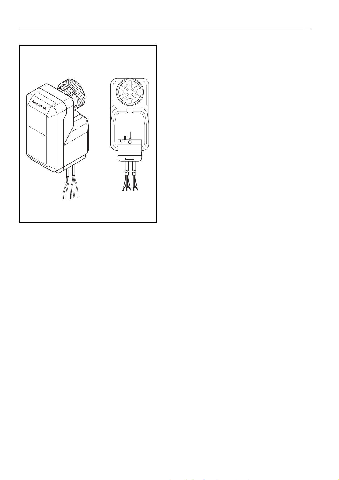
Fig.1 M7410G Actuator
SERVICE LED
STATUS LED
SERVICE PIN
APPLICATION
The M7410G small linear actuator with LON capabilities is
targeted for decentralized building structures and gives
customers an effective new capability in energy management
and product flexibility. The actuator works with standard
SNVTs to provide interoperability with controllers based on
LonWorks technology.
The M7410G actuator is specifically designed to provide
LonMark capabilities together with the radiator and zone valve
series of small linear valves and are used in fan coil units,
induction units, small reheaters, recoolers and for zone
control applications. They are employed in electronic
temperature control systems using hot and / or cold water as
the controlled medium.
The M7410G actuator is suitable for Honeywell Excel series
controllers as well as for any other controllers based on
LonWorks technology. Using standard Echelon configuration
tools, the actuator can be configured with job specific settings.
The M7410G actuator is well suited for applications where
space is limited and minimum power consumption is required.
The actuator is both, attractive and robust in design.
The M7410G actuator is available in two variants, one
standard variant and and a variant with additional PIController. The PI-Controller variant allows the creation of a
control loop independently of an Excel controller for use in
small applications.
• FTT10A communication
• Digital input may used for window or humidity
switch
• The actuator is a flexible tool and LON is a flexible
platform
• Simplifying complex HVAC plants
• Simple wiring
• Open products for third party integration
• Supplied with prewired connection cable
• Simple, standardized valve/actuator coupling
• No tools required for mounting
• Visual valve position indicator furnished with
actuator
• Manual operation provided by the valve adjustment
cap
• High-precision proportional valve actuator
• Standard network variables for ambient
temperature, setpoint temperature, temperature
offset, application mode (Heat / Cool), occupancy or
valve position ensure easiest installation and
proper operation (M7410G1032 / M7410G1040 /
M7410G1057 only)
• Three actuators (M7410G1032 / M7410G1040 /
M7410G1057) are equipped with an additional PI
controller. The combination of actuator and PI
controller in one device makes it easy and cheap to
establish a hydronic or chilled ceiling room control
loop
EN0B-0235 GE51R0802 2
Page 3

PRODUCT DATA
DEVICE SPECIFICATIONS
Input voltage: 24 Vac ± 20 %, 50/60 Hz
Power consumption: 1.4 VA
Input signal: SNVT_lev_percent 0-100%
Control mode: LON (FTT10A)
Stroke: 2.5 - 4 mm 6.5 mm
Running time: 75 s at 50 Hz
63 s at 60 Hz
Stem force: depending on type (see table)
Protection standard: IP 42
Insulation class: III
Connection cable: 1.5 m
Ambient operating
temperature limits:
Weight: 0.3 kg
Suitable valves: see table
Manual operation: see table
0 ... 55 °C
150s at 50
Hz
120s at 60
Hz
OPERATION
The movement of the electric actuator is produced by a screw
spindle which is driven in both directions by a synchronous
motor through a set of gears. A magnetic clutch limits the
torque of the gear assembly and the driving force of the
actuator. The actuator is fixed to the valve body by means of
a coupling ring requiring no tools for mounting. The actuator is
maintenance-free and supplied completely with a ready-towire connecting cable.
VERSIONS
Order Number PI-Controller Force Stroke Compatible Valves
M7410G1008
M7410G1032
M7410G1016
M7410G1040
M7410G1024
M7410G1057
-
z
-
z
-
z
90 N 3.5 mm V100 (Thermostatic valves)
V5822A4 / V5823A4
V5832C4 / V5832A4
V5833A4 / V5833C4
180 N 6.5 mm V5822A / V5832A
V5823A / V5833A
V5823C / V5833C
300 N 6.5 mm V5832B / V5833A
V5872B / V5872D
PLUG-INS, XIF FILES AND DRF FILES
External interface files and the plug-ins (device ressource files included) can be downloaded at http://www.honeywell.de/plugin.
For XIF-files take the link to the LonMark server.
Order Number PlugIn Name XIF-File DRF-File
M7410G1008 / M7410G1016 / M7410G1024 ILONAS ilona_s.xif No
M7410G1032 / M7410G1040 / M7410G1057 ILONASPI ilonaspi.xif Yes
3 EN0B-0235 GE51R0802
Page 4
PRODUCT DATA
PLUG-INS
Plug-Ins give you the possibility to simplify start-up,
maintenance, configuration and to reduce the installation
effort.
XIF FILES
An External Interface File (XIF file) including the whole LON
interface of the device can be used e.g. for offline
configuration or binding of the device via a LON Tool.
For detailed description, please refer to the LNS-Plug-In
Description chapter.
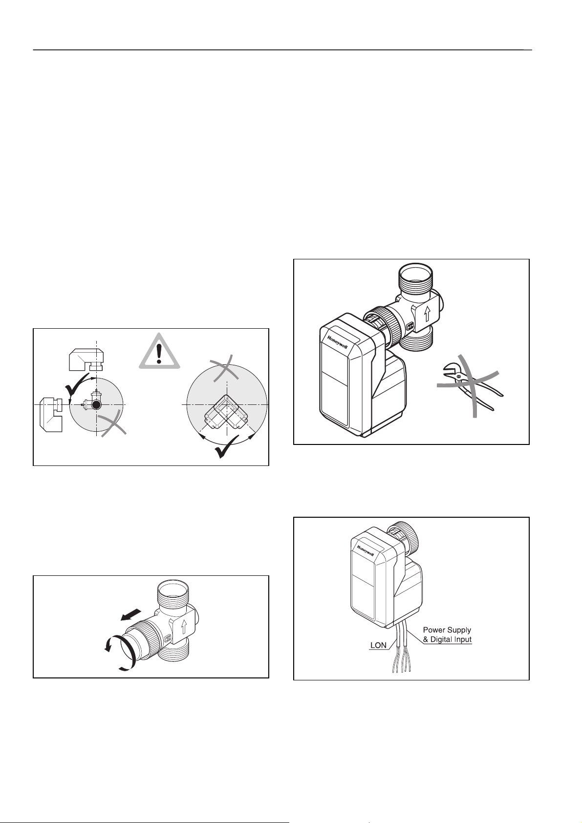
MOUNTING POSITION
The actuator may only be mounted beside or above the
valve. Adjust the valve in the right position before mounting
the actuator.
DRF- FILES
In case a LON network management tool is used, DRF files
must be installed. Device Resource Files (DRF files) are
needed to display special manufacturer defined network
variables or configuration parameters correctly.
Fig.2 Mounting Positions
MOUNTING
Before the actuator is fixed to the valve, the adjustment cap
must be removed (Fig. 2). Make sure that the actuator is in
the open position (factory supplied position) before fixing the
actuator to the valve body.
Fig. 3 Remove Protection Cap
The actuator must be mounted by hand. Don't use tools or
additional forces, because actuator and valve may be
damaged.
Fig. 4 Mounting the Actuator
ELECTRIC WIRING
The electrical installation must comply with the wiring
diagram shown in Fig. 5 and Fig. 6.
Fig. 5 Electric Wiring
EN0B-0235 GE51R0802 4
Page 5
PRODUCT DATA
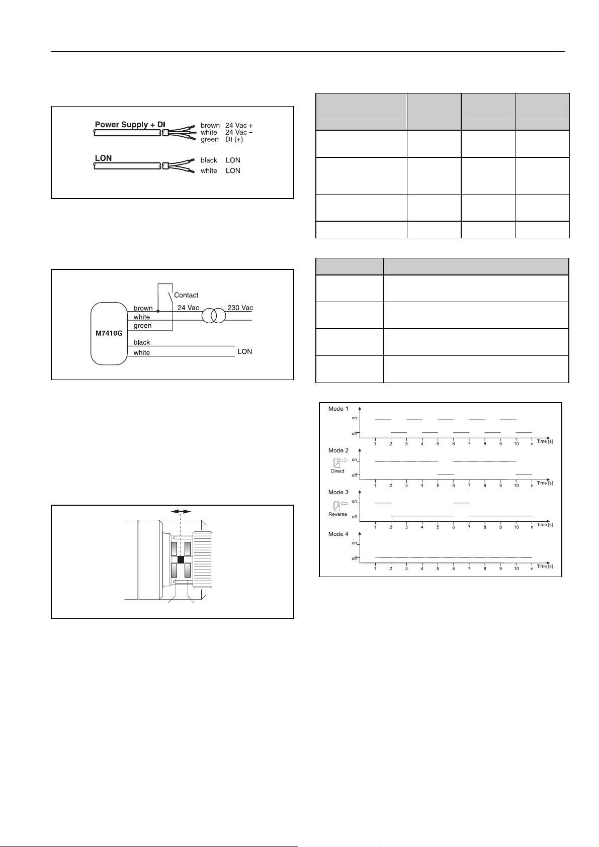
WIRING COLORS
Fig. 6 Wiring Colors
DIGITAL INPUT
Fig. 7 Digital Input
Node state
Service LED
Applicationless and
unconfigured
Unconfigured
(but with an
application)
Configured,
Hard Off-line
Configured 4 off —
Table 1 Node States Service LED
Status LED Blink Modes
Mode 1 1s on, 1s off, for 10 times -
if a wink message was received
Mode 2 4s on, 1s off -
direct acting and normal operation
Mode 3 4s off, 1s on -
reverse acting and normal operation
Mode 4 continuously off -
the device is in the offline-mode
Table 2 Blink Modes Status LED
hF01F
Status
code
3 on 76
2 Flashing 0.51
6 off —
Service
LED
Pulse rate
(Hz)
COMMISSIONING ADVICE
A functional check of the valve actuator can be carried out by
changing the nviManActPos (SNVT_lev_percent).
The movement of the actuator stem (Fig. 7) indicates
whether the valve is opening or closing. If the direction of
travel is not correct, the configuration parameter nciDirRev
(SNVT-state) can be used for changing the direction of
action.
17.8 mm 11.7 mm
Fig. 8 Movement of the Actuator Stem
SERVICE LEDS AND SERVICE PIN DESCRIPTION
Service LED: Defined by Echelon firmware in the neuron
chip (see table 1)
Status LED: Is blinking if wink was sent and indicates
reverse or direct acting
(see table 2 and diagram 1)
Service pin: Accessible under the cover and will be used to
send the neuron ID over the network during
the installation
Diagram 1 Blink Modes Status LED
5 EN0B-0235 GE51R0802
Page 6
PRODUCT DATA
AB
AB
AAB
100% 0%
0% 100%
SERVICE LED
STATUS LED
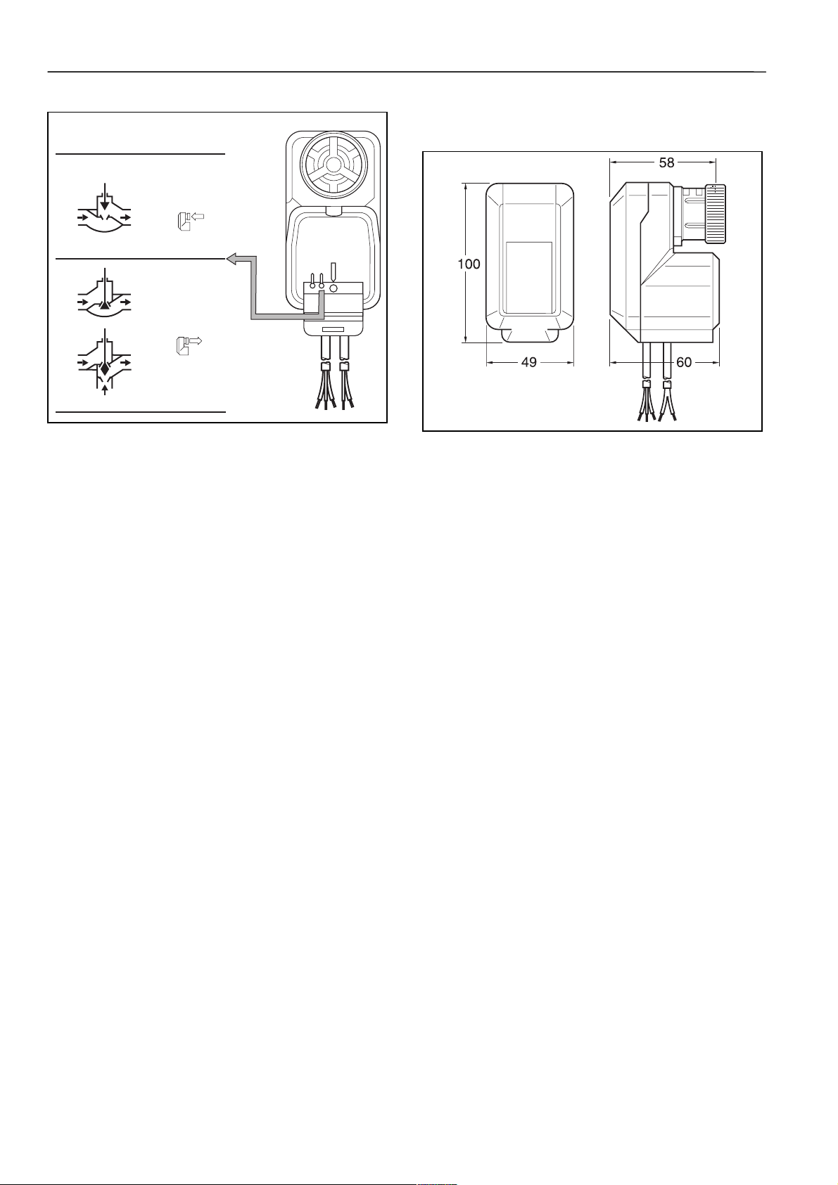
DIMENSIONS (MM)
SERVICE PIN
B
Fig. 9 Selecting Valve Type and Output Signal
Fig. 10 Housing
EN0B-0235 GE51R0802 6
Page 7
LONMARK NETWORK INTERFACE
The Lon Network Interface for the two actuator variants (Standard and with PI-Controller) differs as follows:
Standard With PI-Controller
LON Object M7410G1008
M7410G1016
M7410G1024
Actuator object
Controller object
Node object
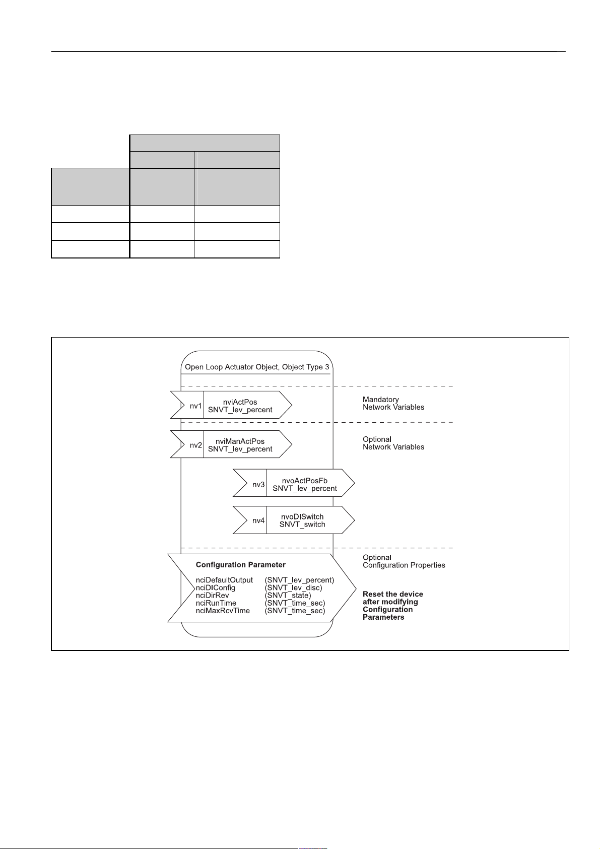
ACTUATOR OBJECT
The actuator object supports the following network variables used for the communication and configuration
Actuator Type
M7410G1032
M7410G1040
M7410G1057
z z
-
-
z
z
PRODUCT DATA
Fig.11 Actuator Object
7 EN0B-0235 GE51R0802
Page 8

PRODUCT DATA
DESCRIPTION OF USED SNVTS* AND SCPTS**
This table shows all used standard network variables and standard configuration parameters, their default values, a short
description, the range and the send conditions and service of the outputs.
Standard Network
Variable
Mandatory
Network Variables
nviActPos
Optional Network
Variables
nvoActPosFb
* SNVTs = Standard Network Variable Types
** SCPTs = Standard Configuration Parameter Types
Type
{Range}
{factory settings}
SNVT_lev_percent
{ 0...100 % ; 163.835}
{163.835} = INVALID
SNVT_lev_percent
{ 0...100 % ; 163.835}
{163.835} = INVALID
Adjustment of the different functionalities and the explanation of the shown
values.
Definition Explanation
nviActPos = 163.835 [INVALID]
⇒ After Power-on or Reset
⇒ Controller is sending [INVALID].
The actuator will run to the safety
position defined in
[nciDefaultOutput].
⇒ Watchdog has “detected”;
Only possible if the watchdog was
selected in [nciMaxRcvTime] and
will correspond on the made
selection in [nciDefaultOutput].
The actuator will run to the safety
position defined in
[nciDefaultOutput].
nviActPos = 0% oder 100%
⇒ Synchronization with full running
time + 30%.
The synchronization can be
interrupted if new values are
received.
(excluding during synchronization
after Power-on or Reset)
0% < nviActPos < 100%
⇒ The actuator runs to the position
received by the controller.
(Exceptional case is after Power on or Reset)
Definition Explanation
nvoActPosFb = 163.835 (INVALID)
⇒ After Power-on or Reset.
⇒ No defined stroke position
feedback possible.
0% <= nvoActPosFb <= 100%
⇒ The actual calculated position of
the stem according to the time to
stroke model.
The actuating signal received from a
controller defined in the range of 0-100%
which defines the stroke position of the
connected valve.
Received values below 0% are calculated like
0% and values over 100% will be calculated
with 100%. The only exception is the value
163.835 = [INVALID]. Is this value received,
the actuator drives to the safety position
which is defined in the [nciDefaultOutput].
The received values will be never overwritten
by the software of the actuator.
The variable [nviActPos] is only be used, if
the variable with higher priority
[nviManActPos] for manual operation is set to
[INVALID] = 163.835.
The cyclic received actuating signal can be
supervised. In this case, the maximum
timeframe for the cyclic received values can
be defined in the configuration parameter
[nciMaxRcvTime].
Is this timeframe passed, the actuator will be
running to the safety position defined in the
configuration parameter [nciDefaultOutput].
This value shows the actual calculated stem
position.
M7410G1008 / M7410G1016 / M7410G1024
For old version ILAS_V1
(stored in sd_string of device)
nvoActPosFb will be updated cyclic every 0,5
sec, if it changes or not. The timing is hard
coded and is not adjustable. So be careful
about making bindings of many actuator
feedback variables, e. g. to a controller for
trending charts. If you have too many output
variables bound to one device it could be
overloaded. If you need this requirement than
make a download of the new controller
software revision ILAS_V2, which has a
behavior as described below. To get the
actual revision contact our Technical
Assistance Center +49-7031-637-760.
EN0B-0235 GE51R0802 8
Page 9

PRODUCT DATA
Optional Network
Variables
nvoActPosFb
nviManActPos
nvoDISwitch
SNVT_lev_percent
{ 0...100 % ; 163.835}
{163.835} = INVALID
SNVT_lev_percent
{ 0...100 % ; 163.835}
{163.835} = INVALID
SNVT_switch
Possible values
1. {0.0 , 0 }
2. {100.0 , 1}
3. {x, 0xFF=255=-1)}
Definition Explanation
nvoActPosFb = 163.835 (INVALID)
⇒ After Power-on or Reset.
⇒ No defined stroke position
feedback possible.
0% <= nvoActPosFb <= 100%
⇒ The actual calculated position of
the stem according to the time to
stroke model.
IMPORTANT:
If control signal requires 0 and 100 %
respectively, then nvoActPosFb turns
immediately to 0 and 100 %
respectively.
nviManActPos = 163.835 (INVALID)
⇒ After Power-on or Reset
⇒ Manual operation is switched off
nviManActPos = 0% or 100%
⇒ Synchronization with full running
time + 30%.
The synchronization can be
interrupted if new values are
received.
(excluding during synchronization
after Power-on or Reset.
0% < nviManActPos < 100%
⇒ The actuator is running to the
manual set value. (Exceptional
case is after Power-on or Reset)
The possible conditions can be
selected by the configuration parameter
[nciDIConfig].
A detailed description is made in the
Selection of Digital Input Usage section.
M7410G1008 / M7410G1016 / M7410G1024
For version ILAS_V2 or higher
(revision stored in sd_string of device)
nvoActPosFb will be measured internally
every 5 sec. If the value changes at the latest
after 5 seconds the value will be updated. If
the value does not change after 60 sec, the
value will be send one time.
M7410G1032 / M7410G1040 / M7410G1057
nvoActPosFb will be measured internally
every 5 seconds. If it changes permanently,
the value will be send maximum every 5
seconds. After 15 minutes the value will be
send one time if it has changed in between or
not.
The actuator can be operated manually. To
have most accuracy a synchronization to the
completely retract position has to be done.
The watchdog [nciMaxRcvTime] is operating
in the background (if selected).
The manual operation has in each case a
higher priority than the received actuating
signal [nviActPos]. After changing the value
for manual operation [nviManActPos] to
[INVALID] the actuator is running according to
the received values of [nviActPos].
Received values below 0% are calculated like
0% and values over 100% will be calculated
with 100%. The only exception is the value
163.835 = [INVALID]. Is this value received,
the actuator drives to the safety position
which is defined in [nciDefaultOutput].
The received values are never overwritten by
the software of the actuator.
Actual state of the sensor, connected to the
digital input (e. g. window-contact or
dewpoint-sensor).
M7410G1008 / M7410G1016 / M7410G1024
For old version ILAS_V1
(stored in sd_string of device)
nvoDIswitch will be updated cyclic every 3
sec if it changes or not. The timing is hard
coded and is not adjustable. So be careful
about making bindings of many digital input
variables, e.g. to a controller for trending
charts. If you have too many output variables
bound to one device it could be overloaded.
If you need this requirement than make a
download of the new controller software
revision ILAS_V2, which has a behavior as
described below. To get the actual revision
contact our Technical Assistance Center +497031-637-760.
For version ILAS_V2 or higher
(revision stored in sd_string of device)
nvoDIswitch will be measured internally
every 5 sec. If the value changes at the latest
after 5 seconds the value will be updated. If
the value doesn’t changes after 60 sec the
value will be send one time.
M7410G1032 / M7410G1040 / M7410G1057
nvoDIswitch will be measured internally every
5 seconds. If it changes, the value will be
send at the latest after 5 seconds. After 15
minutes the value will be send one time if it
has changed in between or not.
9 EN0B-0235 GE51R0802
Page 10

PRODUCT DATA
Standard
Configuration
Parameters
Definition Explanation
nciDirRev
nciMaxRcvTime
nciDefaultOutput
nciDIconfig
nciRunTime
SCPT Master List -
Names from
Echelon
SCPTdirection
SCPTmaxRcvTime SNVT_time_sec
SCPTdefOutput SNVT_lev_percent
SCPTinvrtOut SNVT_lev_disc
SCPTDriveTime SNVT_time_sec
Type
{Range}
{factory settings}
SNVT_state
{Bits = 1 or 0}
M7410G1008 /-16 /-24
{1111111111111111}
M7410G1032 /-40 /-57
{1000000000000000}
{0...6553 sec}
{0}
Only integer values are
accepted and numbers
after a comma will be
ignored.
{ 0; 100 % ; 163.835}
{163.835} = INVALID
{ST_ON}
{ST_OFF}
{0...6553.5 sec}
{6553.5} = INVALID
Adjustment of the different functionalities and the explanation of
the shown values.
Is no value [nviActPos], in a certain
timeframe [nciMaxRcvTime]
received, the actuator will run to the
position defined in
[nciDefaultOutput].
This is called a heartbeat control or
watchdog function.
This configuration parameter defines
the condition what will happen if the
timeframe [nciMaxRcvTime] of the
watchdog is passed or if an
undefined situation takes place.
For example: The controller failed
and no values are received. In this
case the actuator can run to a safety
position or stops immediately. The
selection should be done according
to the applications requirements.
See Selection of Digital Input Usage
section
The selection of the running time will
be done automatically.
To adapt the valve stroke to the
running time afterwards and to
secure the accuracy for the time to
stroke model this configuration
parameter is used.
Inverse the direction of action
M7410G1008 / -16 / -24
1111111111111111= Direct
0000000000000000 = Reverse
M7410G1032 / -40 / -57
Bit 0 = 1 ⇒ Direct
Bit 0 = 0 ⇒ Reverse
Watchdog for the Controller /
Actuator supervision
[nciMaxRcvTime] = 0
Watchdog is deactivated
[nciMaxRcvTime] =
for example 60 [sec]
Watchdog expires, if for 60
seconds no new value is
received on [nviActPos]. The
actuator will run to the position,
defined in the configuration
parameter [nciDefaultOutput].
Safety position in case of
controller failure
100 % = Actuator will do a
synchronization to 100 %, 100%
running time +30% safety.
0 % = Actuator will do an
synchronization to 0%, 100%
running time +30% safety.
[INVALID] = 163.835 = Actuator
stops immediately
All other values are the same as
163.835
Configuration of the digital input
Possibility of overwriting the
value for the running time, which
is normally done automatically.
This should only be done in case
of adapting a different valve to
the actuator.
Setting nciRunTime to
(INVALID) and resetting the
node, the selection of runtime will
be as factory setting.
The running time is automatically
selected and depending on the
power supply frequency
[50Hz/60Hz] which is measured
by the hard-/software
environment.
EN0B-0235 GE51R0802 10
Page 11

SELECTION OF DIGITAL INPUT USAGE
PRODUCT DATA
Network variable
Configuration parameter
(SCPT...nciDIconfig)
Type: SNVT_lev_disc
default:
nciDIconfig
=ST_OFF
switch
nciDIconfig =
ST_ON
nciDIconfig = ST_NUL (0xFF)
switch
closed
switch
opened
opened
switch
closed
(SNVT...nvoDIswitch)
Type: SNVT_switch
Value State User
100.0 1 X
0 0 x
100.0 1 X
0 0 x
0 0xFF (=255=-1) x
WATCHDOG FOR THE SUPERVISION OF THE ACTUATION SIGNAL
Activation of the watchdog-timer
Is the SCPT [nciMaxRcvTime] set to 0, the watchdog is
generally switched off. To activate the watchdog, a value >0
has to be selected. This value has to be in the range of
values. Values after a comma will be ignored.
Start of the watchdog-timer after Power-on
The watchdog-timer is starting after a first value was received
by [nviActPos]. Up to that point, the actuator will stay in the
defined safety position [nciDefaultOutput].
Watchdog-timer in case of manual operation.
Is the actuator working in the manual operation mode
(nviManActPos
the background. This means, if the controller fails, the
watchdog-timer expires and after switching manual operation
[nviManActPos] to [INVALID] the actuator is running to the
safety position according to the definition in
[nciDefaultOutput].
≠ INVALID) the watchdog-timer is working in
FACTORY SETTINGS
State of the Network and Configuration Parameters:
nviActPos = 163.835 (INVALID)
nviManActPos = 163.835 (INVALID)
nviActPosFb = 163.835 (INVALID)
nvoDIswitch = [ 0.0 -1 ]
after initialization (3 sec.) = [ 0.0 0 ]
(if there is no switch connected)
nciDefaultOutput = 163.835 (INVALID)
nciDirRev = 1111111111111111
(for M7410G1008 / -16 / -24)
nciDirRev = 100000000000000
(for M7410G1032 / -40 / -57)
nciMaxRcvTime = 0.0 sec
nciDIconfig = ST_OFF
nciRunTime = 6553.5 (INVALID)
Meaning
defined
DI not used or device
offline or first 3 sec after
Power-on/Reset/online
BEHAVIOR OF THE ACTUATOR AFTER POWER-ON / RESET / OFFLINE-ONLINE
The behavior of the motor is dependent on the configuration
parameter nciDefaultOutput.
There are three possible states.
nciDefaultOutput Behavior of the motor after
default:
163.835 = INVALID
0 % The actuator synchronizes to the position
100 % The actuator synchronizes to the position
Power-on / Reset
The actuator makes no movement and
waits. The first received value from the
controller or manual will be saved as the
actual position of the motor - no
movement. The second received value
will be compared to the first, and the
motor runs to the new required position
(and so on...).
referring to 0 % and runs then to the
position according to the controller/
manual value, if one is received.
If not, the actuator waits.
referring to 100 % and runs then to the
position according to the controller/
manual value, if one is received.
If not, the actuator waits.
INTERRUPTION OF THE SYNCHRONIZATION
The interruption of the synchronization after Power-on / Reset
(nciDefaultOutput = 0 or 100 %) is not possible. Later
synchronizations can be interrupted every time.
11 EN0B-0235 GE51R0802
Page 12

PRODUCT DATA
WHAT HAPPENS AT OFFLINE-ONLINE MODE
CHANGES
If the actuator is taken offline by a network management tool
the application program of the device stops, and the following
actions will be done before the offline mode takes place:
Online-Offline change
• The motor stops, if it is running
• The Status LED is taken off
• The network variable
(163.835), to show that the actuator is in a undefined
situation
• The state-value of the network variable
set to INVALID (255 = 0xFF = -1), to show that the
actuator is in a undefined situation.
nviActPosFb will be set to INVALID
nviDIswitch will be
Offline-Online change
• Application restart. Same situation as Power-on or Reset.
EN0B-0235 GE51R0802 12
Page 13

CONTROLLER OBJECT (ACTUATORS WITH PI-CONTROLLER ONLY)
The controller object supports the following network variables used for the communication and configuration
Controller Object
Controller Object, Object Type 5
PRODUCT DATA
nviActualTemp
nv1
SNVT_temp_p
nviSetpoint
nv2
SNVT_temp_p
nviSetPtOffset
nv3
SNVT_temp_p
nviEnergyHoldOff
nv4
SNVT_switch
nviOccupancy
nv5
SNVT_occupancy
nviApplicMode
nv5
SNVT_hvac_mode
Configuration Parameter
nc 78 - nciSetpoint (SNVT_temp_p)
UCPT - nciPIGains[2]
UCPT - nciPIConfig (Heat / Cool)
nvoValvePosition
nv7
SNVT_lev_percent
nciPIGains.pi_Xp (SNVT_temp_p)
nciPIGains.pi_Tn (SNVT_time_sec)
Network Variables
Optional
Configuration Properties
Modify SCPT´s anytime (no reset of
device)
Fig.12 Controller Object
13 EN0B-0235 GE51R0802
Page 14

PRODUCT DATA
DESCRIPTION OF USED SNVTS AND SCPTS
This table shows all used standard network variables and standard configuration parameters, their default values, a short
description, the range and the send conditions and service of the outputs.
Standard Network
Variable
Network Variables
nviActualTemp
nviSetpoint
nviSetPtOffset
nviEnergyHoldOff
nviOccupancy
Type
{Range}
{factory settings}
SNVT_temp_p
{-163,80 to 163,80;
327,67}
{327,67} = INVALID
SNVT_temp_p
{-157,80 to 157,80 [°C]
327,67}
{327,67} = INVALID
SNVT_temp_p
{-157,80 to 157,80 [°C];
327,67}
{327,67} = INVALID
SNVT_switch
Possible values:
Value/State
1.) {0,0;0}
2.) {>0;1}
{0,0;-1}
SNVT_occupancy
{ OC_OCCUPIED,
OC_UNOCCUPIED,
OC_BYPASS,
OC_STANDBY,
OC_NUL}
{OC_NUL}
Adjustment of the different functionalities and the explanation of the shown
values.
Definition Explanation
nviActualTemp = 327,67 [INVALID]
⇒ after Power on or Reset.
If nviActualTemp is INVALID than
nvoValvePosition will be Invalid, too,
cause no control loop is possible.
not equal 327,67 [INVALID]
⇒ normal operation
If nviActualTemp is not INVALID
than normal operation is possible.
nviSetpoint = 327,67 [INVALID]
⇒ after power on or reset.
If nviSetpoint is INVALID the internal
nciSetpoint will be used as the
actual required temperature.
nviSetpoint not equal 327,67 [INVALID]
⇒ normal operation
If nviSetpoint is not INVALID than this
parameter has higher priority than the
setpoint adjusted in the SCPT nciSetpoint
nviSetPtOffset = 327,67 [INVALID]
⇒ after Power on or Reset.
If nviSetPtOffset is INVALID than it
will be ignored.
nviSetpoint not equal 327,67 [INVALID]
⇒ normal operation
If nviSetptOffset is not INVALID it will be
added to the actual valid setpoint
{ 0.0,0} the controller works in
normal operation mode
{100,1} the value nvoValvePosition
will be overwritten with 0
%. So energy will be
switched off.
All other cases have the same meaning
than {0.0,0}
Description from LonMark
0 OC_OCCUPIED
Area is occupied
1 OC_UNOCCUPIED
Area is unoccupied
2 OC_BYPASS
Area is temporarily occupied
for the bypass period
3 OC_STANDBY
Area is temporarily unoccupied
0xFF OC_NUL
Value not available
nviActualTemp includes the actual
temperature delivered by an separate LON
temperature sensor.
Received values below –163,80°C are
calculated like –163,80°C and values above
163,80°C will be calculated with 163,80°C.
The only exception is the value 327,67 =
[INVALID]. Is this value received, the output
of the controller nvoValvePosition will be
set to INVALID, too.
Received values below –157,80°C are
calculated like –157,80°C and values above
157,80°C will be calculated with 157,80°C.
The only exception is the value 327,67 =
[INVALID]. Is this value received, the
internally setpoint [nciSetpoint] will be taken
as the actual one.
If the SNVT nviSetPtOffset is not INVALID
than the required temperature will be
evaluated like this.
Setpoint = nviSetpoint + nviSetPtOffset
nviSetPtOffset works together with
nviSetpoint or nciSetpoint and is part of the
actual required temperature.
Received values below –157,80°C are
calculated like –157,80°C and values above
157,80°C will be calculated with 157,80°C.
The only exception is the value 327,67 =
[INVALID]. Is this value received, it will be
ignored.
Can be used for binding of a physical digital
input, e.g. nvoDIswitch from the internal
actuator object. So the energy could be
saved if an open window or a dewpoint
sensor detects a situation to switch off the
energy = close the valve totally. This means
no more heating in HEATING applications
or no more cooling in COOLING
applications
For binding of an occupancy sensor.
The state has influence on the setpoint
to optimize the energy consumption.
Heating
If [OC_NUL] or
[OCCUPIED] or
[OC_BYPASS] 0 K substracted from
setpoint
If [OC_STANDBY] 3 K substracted from
setpoint
If [OC_UNOCCUPIED] 6 K substracted
from setpoint
EN0B-0235 GE51R0802 14
Page 15

PRODUCT DATA
Cooling
If [OC_NUL] or
[OCCUPIED] or
[OC_BYPASS] 0 K added to setpoint
If [OC_STANDBY] 3 K added to setpoint
If [OC_UNOCCUPIED] 6 K added to
setpoint
K = Kelvin
nviApplicMode
nvoValvePosition
SNVT_hvac_mode
{ HVAC_AUTO,
HVAC_HEAT,
HVAC_MRNG_WRMUP
HVAC_COOL,
HVAC_NIGHT_PURGE,
HVAC_PRE_COOL,
HVAC_OFF,
HVAC_TEST,
HVAC_EMERG_HEAT,
HVAC_FAN_ONLY,
HVAC_FREE_COOL,
HVAC_ICE,
HVAC_NUL}
{HVAC_NUL}
SNVT_lev_percent
{0-100; 163,835}
{163,835} = INVALID
Description from LonMark:
0 HVAC_AUTO
1 HVAC_HEAT
2 HVAC_MRNG_WRMUP
3 HVAC_COOL
4 HVAC_PRE_COOL
5 HVAC_NIGHT_PURGE
6 HVAC_PRE_COOL
7 HVAC_OFF
8 HVAC_TEST
9 HVAC_EMERG_HEAT
10 HVAC_FAN_ONLY
11 HVAC_FREE_COOL
12 HVAC_ICE
0xFF HVAC_NUL
nvoValvePosition = 163,835 [INVALID]
⇒ after Power on or Reset.
PI-Controller cannot deliver a
required actuator position
If nvActualTemp is not INVALID
⇒ nvoValvePosition = 0...100 %
Required Actuator / Valve
position
If [HVAC_HEAT] than nciPiConfig will be
overwritten and HEAT Application is active.
If [HVAC_COOL] than nciPiConfig will be
overwritten and COOL Application is active.
If nviApplicMode is not [HVAC_HEAT] and
not [HVAC_COOL] than the Application
mode will be adjusted via nciPiConfig.
IMPORTANT:
If application mode changes than the picontroller will be reseted internally.
nvoValvePosition includes the actual
required valve position. This parameter
could be bound with the SNVT nviActPos of
the internal actuator object.
IMPORTANT:
If nvoValvePosition changes it will be send
at the latest within 5 seconds. After 15
minutes the value will be send one time if it
has changed in between or not .
RELATION BETWEEN NVIOCCUPANCY, NCISETPOINT, NVISETPOINT AND NVISETPTOFFSET
The adjusted value via nviOccupancy (0 K, 3K or 6K)
⇒ will be ADDED to the actual setpoint in COOLING MODE
⇒ will be SUBSTRACTED from the actual setpoint in HEATING MODE
OC_NUL
OC_OCCUPIED
OC_BYPASS
± 0 K
OC_STANDBY ... ± 3 K
OC_UNOCCUPIED ... ± 6 K
15 0C 18 0C
21 0C
24 0C27
0
C
nciSetpoint + nviSetPtOffset
or
nviSetpoint + nviSetPtOffset
Example 1: nviSetpoint = INVALID, nciSetpoint = 21 °C, nviSetPtOffset = 5 K,
nviOccupancy = OC_STANDBY, nciPiConfig = HEAT, nviApplicMode = INVALID
0C
[
]
15 EN0B-0235 GE51R0802
Page 16

PRODUCT DATA
Actual Setpoint = nciSetpoint + nviSetPtOffset – occupancy_value
= 21°C + 5K
Example 2: nviSetpoint = 23°C, nviSetPtOffset = -4 K, nviOccupancy = OC_UNOCCUPIED,
nciPiConfig = COOL, nviApplicMode = INVALID
Actual Setpoint = nviSetpoint + nviSetPtOffset – occupancy_value
= 23°C – 4K
Standard
Configuration
parameter
nciPiConfig
nciPiGains
nciSetpoint SCPTheatSetpt SNVT_temp_p
SCPT Master
List – names
from Echelon or
User defined
Types
UCPT_PiConfig
UCPT_PiGains
Type
{Range}
{factory settings}
UNVT_PiConfig
{
0 = HEAT;
1 = COOL;
}
{HEAT}
If application mode changes than the pi-controller
will be reseted internally.
UNVT_PiGains
nciPiGains.pi_Xp [SNVT_tmp_p]
{3 – 25 [K]}
{4}
nciPiGains.pi_Tn [SNVT_time_sec]
{10 – 1000 [sec]}
{300}
{-157,80 - 157,80 [°C]}
{21°C}
– 3K = 23 °C
+ 6 K = 25°C
Adjustment of the different functionalities
and the explanation of the shown values.
Decides if a heating or a cooling application
should be controlled. nciPiConfig is only the
decider if nviApplicMode is not set to
HVAC_HEAT or HVAC_COOL. In this cases
nviApplicMode decides if a heating or a
cooling application is active.
Regardless you have the HVAC mode HEAT
or COOL , the internal frost protection
function starts working if the actual
temperature reaches the critical value < 6 ° C.
In this case the value nvoValvePosition will
be overriden with 100 % in heating mode and
with 0 % in cooling mode. So there will be
prevent damages caused by too low
temperature. If a value of > 8 °C is reached
the frost protection will be switched off again.
nciPiGains.pi_Xp =
p value of pi controller
nciPiGains.pi_Tn =
i value of pi controller in
If the temperature deviation between setpoint
and actual temperature is higher than 4,8 K
the linearity of the P-portion gets lost and the
P-Control is working in a limited range. In this
case the I-Portion takes care for accurate
controlling.
The setpoint is the actual required
temperature. If the SNVT nviSetPtOffset is
not 0 than the required temperature will be
evaluated like this.
Setpoint = nciSetpoint + nviSetPtOffset
Values below –157,80°C are calculated like –
157,80°C and values above 157,80°C will be
calculated with 157,80°C.
EN0B-0235 GE51R0802 16
Page 17

PRODUCT DATA
PRIORITIES OF THE DIFFERENT POSSIBLE SITUATIONS
Prio Action Occurs... nvoValvePosition will be set to...
1 Frost Protection ...if the actual temperature runs below 6 ° C. Frost Protection
2 Energy Off ...if nviEnergyHoldOff, which displays the state of a physical
3 no control loop
possible
4 Normal Operation ...if priorities 1-3 are not active. PI-Algorithm works. The
mode is active till temperature rises above 8° C.
digital switch, turns to [value>0,state=1].
...if nviActualTemp is [INVALID] than nvoValvePosition will be
set to INVALID, too.
If the bound internal Actuator (nviActPos) receives INVALID
from nvoValvePosition it runs to the adjustable safety position.
The safety position could be adjusted in the actuator object
via variable nciDefaultOutput.
actual required valve position will be evaluated.
100 % if heating mode
0 % if cooling mode
0 %
163,835 [INVALID]
the valve position evaluated by the PIalgorithm
FACTORY SETTINGS
State of the SNVTs/SCPTs (factory setting):
nviSetpoint = 327,67 (INVALID)
nviSetptOffset = 327,67 (INVALID)
nviActualTemp = 327,67 (INVALID)
nviOccupancy = OC_NUL
nviEnergyHoldOff = {0,0;-1}
nviApplicMode = HVAC_NUL
nvoValvePosition = 163.835 (INVALID)
nciPiConfig = HEAT
nciPiGains.pi_Xp = 4
nciPiGains.pi_Tn = 300
nciSetpoint = 21 °C
BEHAVIOUR OF THE CONTROLLER AFTER POWER ON / RESET / OFFLINE-ONLINE
If power-on or reset or offline to online happens an application reset occurs.
Used PI-Algorithm
%100
jG
ϖ
)(
1
+×=
ϖ
1
Tjxp
×
N
Xp = Proportional band [nciPiGains.pi_Xp]
T
= Integral reset time [nciPiGains.pi_Tn]
N
17 EN0B-0235 GE51R0802
Page 18

PRODUCT DATA
NODE OBJECT (ACTUATORS WITH PI-CONTROLLER ONLY)
The node object is implemented to fullfill the LonMark guidelines, but it has no functionallity in this device.
Node Object
Node Object, Object Type 0
nviRequest
nv1
SNVT_obj_request
nvoStatus
nv2
SNVT_obj_status
None
Fig.13 Node Object
Mandotary
Network
Variables
Optional
Configuration
Properties
EN0B-0235 GE51R0802 18
Page 19

LNS PLUG-IN DESCRIPTION
ACTUATOR OBJECT
DIAGNOSTIC AND TEST
The following descriptions apply to both actuator types (with / without PI-controller).
PRODUCT DATA
Fig.14 Diagnostic and Test Screen
There are two Plug-In versions available, one for each type of actuator (with / without PI-controller).
Monitor Shows the current status of the actuator and of the physical digital input.
REQUESTED ACTUATOR POSITION (nviActPos)
Monitoring of the requested actuator position of the controller.
The range of nviActPos is 0...100 %. Received values below 0 % are calculated like 0 % and values
above 100 % will be calculated like 100 %. The only exception is the value 163.835 % = [INVALID]. Is
this value received the actuator drives to the safety positon adjusted in the Configuration dialog box.
100 % means synchronization to the 100 % - position with 130 % running of full motor runtime. The
synchronization can be interrupted.
Special Case: power on / reset / offline-online.
The synchronization caused by nciDefaultOutput can not be interrupted.
0 % means synchronization to the 0 % - position with 130 % running of full motor runtime. The
synchronization can be interrupted.
Special Case: power on / reset / offline-online.
The synchronization caused by nciDefaultOutput can not be interrupted.
CALCULATED ACTUATOR FEEDBACK (nvoActPosFb)
Monitoring of the actual calculated actuator position. It is important to know that the internal
synchronous motor has no physical feedback sensor. The shown feedback is only a calculated value
and should only be used for trend diagrams or to check motor movements. The correctness of this
value is not guaranteed. The range of nviActPosFb is 0...100 %. (The invalid-string signalizes an
undefined situation). For send timing description, please refer to "Description of used SNVTS* and
SCPTS" section.
19 EN0B-0235 GE51R0802
Page 20

PRODUCT DATA
STATE OF PHYSICAL DIGITAL INPUT (nvoDIswitch)
Monitoring of the actual state of the sensor connected to the physical digital input. (e.g. window-contact
or dewpoint-sensor). The possible conditions can be selected by the [Digital Input – Mode] – field on
the Configuration - dialog box. The states of nvoDIswitch can be ON / OFF / INVALID. For send timing
description, please refer to "Description of used SNVTS* and SCPTS" section.
Manual Override Allows to operate the actuator manually.
MANUAL REQUESTED ACTUATOR POSITION (nviManActPos)
To operate the actuator manually, click check box and enter desired value:
The manual operation has in each case a higher priority than the received controller signal [nviActPos].
The range of nviManActPos is 0...100 %. Received values below 0 % are calculated like 0 % and
values above 100 % will be calculated like 100 %.
100 % means synchronization to the 100 % - position with 130 % runningnof full motor runtime. The
synchronization can be interrupted.
Special Case: power on / reset / offline-online.
The synchronization caused by nciDefaultOutput can not be interrupted.
0 % means synchronization to the 0 % - position with 130 % running of full motor runtime. The
synchronization can be interrupted.
Special Case: power on / reset / offline-online.
The synchronization caused by nciDefaultOutput can not be interrupted.
To have most accuracy with the manual override a synchronization to the stem completely retract
position has to be done.
After switching off the manual override the actuator is running according to the received controller
values (nviActPos).
CONFIGURATION SCREEN
The following descriptions apply to both actuator types (with / without PI-controller).
Actuator Settings
Configures the functionality of the actuator and the physical digital input.
Fig.15 Configuration Screen
EN0B-0235 GE51R0802 20
Page 21

Direct / Reverse - Mode Inverses the direction of action
(nciDirRev)
Service PIN
MODE 1
(10x)1 sec 1 sec
nviActPos
MODE 2
Direct
SNVT_Lev_percent
PRODUCT DATA
Neuron ID
Wink
4 sec 1 sec
AB
100% 0%
SERVICE LED
STATUS LED
SERVICE PIN
MODE 3
Reverse
4 sec1 sec
MODE 4
off
DIRECT_MODE
Requested actuator position = 0 %. Actuator runs to position “stem totally extract”.
Requested actuator position = 100 %. Actuator runs to position “stem totally retract”.
Status LED blinking: 4s on / 1 s off (Mode 2).
REVERSE_MODE
Requested actuator position = 0 %. Actuator runs to position stem totally retract.
Requested actuator position = 100 %. Actuator runs to position stem totally extract.
Status LED blinking: 1s on / 4 s off (Mode 3).
Heartbeat Heartbeat of the connected controller.
(nciMaxRcvTime)
MAXIMUM RECEIVE TIME
Is no requested actuator position value (nviActPos) received in a certain timeframe
defined in the [Heartbeat] - field, the actuator will run to the position defined in the
[Safety Position] - field.
MAXIMUM RECEIVE TIME = 0 seconds. Heartbeat supervision = OFF
0 < MAXIMUM RECEIVE TIME <= 6553 seconds. Heartbeat supervision = ON and timeframe
adjusted.
Additional information
Only integer values are accepted and numbers after a comma will be ignored.
AB
0% 100%
AAB
B
Offline
Fig.16 Modes
21 EN0B-0235 GE51R0802
Page 22

PRODUCT DATA
Start of the heartbeat supervision after power on / reset / offline-online:
The heartbeat supervision starts after a first value was received by the controller (nviActPos). Up to that
point, the actuator will stay in the defined safety position (nciDefaultOutput).
Heartbeat supervision in case of manual operation.
When the actuator is working in the manual operation mode ([nviManActPos] active), the heartbeat
supervision is working in the backround. This means, if the controller fails, the timeframe is passed.
Then the manual operation is switched off, and the actuator is running to the definition of the [Safety
Position] - field.
Safety Position Safety position of the actuator in case of controller failure, power on / reset / offline-(nciDefaultOutput)
online or any other undefined situation.
Defines the condition what will happen if the timeframe defined in the [Heartbeat] - field is passed or if
an undefined situation like power on / reset / offline-online occurs.
100 %
The actuator will do a synchronization to the 100 % - position with 130 % running of full motor runtime.
The synchronization can be interrupted.
Special Case: power on / reset / offline-online.
The synchronization can not be interrupted.
0 %
The actuator will do a synchronization to the 0 % - position with 130 % running of full motor runtime.
The synchronization can be interrupted.
Special Case: power on / reset / offline-online.
The synchronization can not be interrupted.
STOP_MOVEMENT
Actuator stops immediately.
Special Case: power on / reset / offline-online.
The Actuator makes no movement and waits. The first received value for the requested position from
the controller or manual override will be saved as the actual position of the motor – no movement. The
second received value will be compared to the first, and the motor runs to the new required position
(and so on...).
Digital Input - Mode Configuration of the digital input.
(nciDIswitch)
Digital Input – Mode (nciDIswitch)
[Configuration-dialog box]
Switch closed ON NORMALLY OPEN
Switch opened OFF
Switch opened ON NORMALLY CLOSED
Switch closed OFF
NOT USED Switch ignored INVALID*
* The invalid-string is shown the first three seconds after power on / reset / online - offline till the
initialization of the actuator is finished too)
Motor Runtime Possibility of overwriting the automatically detected motor runtime and to secure the
(nciRunTime)accuracy for the time to stroke model. This should only be done in case of adapting a
different valve to the actuator
AUTOMATIC
After power on / reset / offline-online the actuator automatically detects the motor runtime and software
adapts the motor runtime to the 50 / 60 Hz mains frequency.
MANUAL
If the manual mode is activated it is possible to adjust another motor runtime
(the values 0 and 6553,5 are not allowed).
General Information
The actuator automatically sends a service pin message after power on / reset / offline- online.
If the Actuator receives a wink message (executed by the network management tool) the status LED is blinking 10 times with a
frequncy of one second and so the actuator could be located in the field.
State of Digital Input (nvoDIswitch)
[Diagnostic and Test – dialog box]
EN0B-0235 GE51R0802 22
Page 23

PRODUCT DATA
ONLINE-OFFLINE change executed by the network management tool:
• The motor stops if it is running
• The status LED is taken off
• The calculated actuator feedback (nvoActPosFb) will be set to INVALID, to show that the actuator is in an undefined situation.
• The state of the physical digital input will be set to INVALID.
OFFLINE-ONLINE change executed by the network management tool:
• Application restart. Same situation as power-on / reset
Wiring Diagram
Diagram 2: Wiring
Wiring Colors
Power Supply + Digital Input
Brown 24 Vac +
White 24 Vac Green DI (+)
LON (E-Bus)
Black LON
White LON
Input Voltage: Input Voltage for power supply
24 Vac ± 20 %, 50 / 60 Hz
LON (E-Bus): Connection of the LON Bus FTT-10A. The LON Bus is insensitive to polarity, eliminating wiring errors during
installation.
Connection
Cable: 1,5 m
23 EN0B-0235 GE51R0802
Page 24

PRODUCT DATA
PI-CONTROLLER OBJECT
The PI-Controller Descriptions of the Plug-In only apply to the actuator types which have the PI-Controller
integrated.
MONITORING
Fig.17 Monitoring Screen
Priority Table
EN0B-0235 GE51R0802 24
Page 25

PRODUCT DATA
Actual and Required ACTUAL TEMPERATURE (nviActualTemp)
Temperature Shows the actual temperature received from a LON temperature sensor. For INVALID state refer to the
priority table above (priority 3).
EFFECTIVE SETPOINT
The effective setpoint is the required temperature which depends on the
- Application Mode (nviApplicMode or nciPiConfig)
- the Setpoint (nviSetpoint or nciSetpoint)
- the Setpoint Offset (nviSetPtOffset)
- the Occupancy State (nviOccupancy)
Output of PI- REQUIRED VALVE POSITION (nvoValvePosition)
Controller Shows the required valve position evaluated from the PI-controller.
For the different priorities refer to the priority table above.
Further Values HEATING OR COOLING MODE ADJUSTED (nviApplicMode)
for PI-Control If the HEATING mode is adjusted via nviApplicMode, the internal configuration parameter nciPiConfig
will be overridden and the controller works in the HEATING application mode.
If the COOLING mode is adjusted via nviApplicMode, the internal configuration parameter nciPiConfig
will be overridden and the controller works in the COOLING application mode.
If the nviApplicMode edit field shows INVALID, the application mode will be adjusted via the internal
configuration parameter nciPiConfig.
If the application mode changes between HEATING and COOLING, the PI-controller will be reset
internally.
EXTERNAL TEMPERATURE SETPOINT (nviSetpoint)
Shows the temperature setpoint adjusted from the outside of the device. If this value is adjusted, the
internal configuration parameter nciSetpoint will be overwritten. If nviSetpoint shows INVALID, the
internal setpoint (nciSetpoint) is active.
TEMPERATURE SETPOINT OFFSET (nviSetPtOffset)
Shows the temperature offset adjusted from the outside of the device.
STATE OF OCCUPANCY (nviOccupancy)
Shows the actual occupancy state received from a occupancy sensor.
For description, see the table below.
VALUE ADDED TO SETPOINT CAUSED BY OCCUPANCY (nviOccupancy)
For description, see the table above.
SAVE ENERGY SWITCH (nviEnergyHoldOff)
For the behaviour of the controller if nviEnergyHoldOff turns to ON, refer to the priority table above
(priority 2)
.
25 EN0B-0235 GE51R0802
Page 26

PRODUCT DATA
CONFIGURATION OF PI-CONTROLLER
If nviApplicMode APPLICATION MODE (nciPiConfig)
is invalid Defines whether the controller should work in heating or cooling application mode. Internal
configuration parameter nciPiConfig is only active, if external nviApplicMode is inactive (INVALID).
If the application mode changes between HEATING and COOLING, the PI-controller will be reset
internally.
Adjustment of PI- PROPORTIONAL BAND (Xp)
Control Parameters Temperature deviation between the required temperature (effective setpoint) and the actual
temperature (nviActualTemp), which causes the control output to modulate from 0 % to 100 %
(nvoValvePosition).
INTEGRAL RESET TIME (Tn)
Integral reset time of the PI-controller.
If nviSetpoint INTERNAL SETPOINT (nciSetpoint)
is invalid Actual internal adjusted setpoint. This variable is only VALID if the external setpoint (nviSetpoint) is
INVALID.
EN0B-0235 GE51R0802 26
Page 27

PRODUCT DATA
APPLICATION EXAMPLE FOR M7410G1032 / M7410G1040 / M7410G1057
The following picture shows the easiest way for a complete decentral temperature control loop with an additional Energy Hold
Off signal from, e.g. a dewpoint sensor or a window contact.
27 EN0B-0235 GE51R0802
Page 28

Home and Building Control
Honeywell AG
Böblinger Straβe 17
D-71101 Schönaich
Phone: (49) 7031 63701
Fax: (49) 7031 637493
http://europe.hbc.honeywell.com
Subject to change without notice. Printed in Germany Manufacturing location certified to
EN0B-0235 GE51R0802
 Loading...