

Page 1
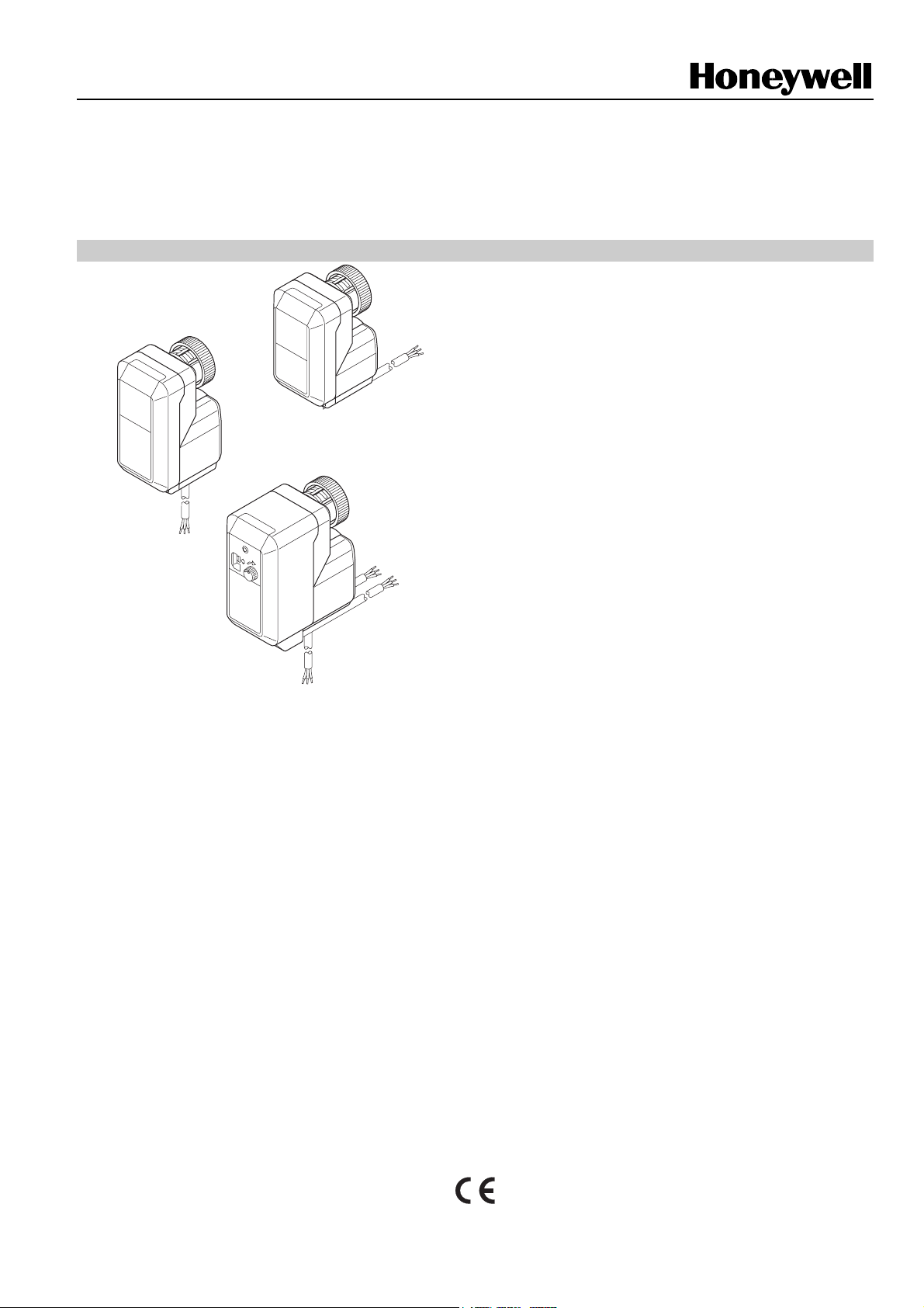
M6410C/L, M7410C
Small 3-Position Linear Valve Actuators
PRODUCT DATA
FEATURES
• Small size allows installation where space is limited
• Low power consumption
• Reliable longtime operation because mechanical
feedback potentiometers and mechanical end
switches are not required
• Magnetic coupling for stem force limitation and self-
adjustment of the close-off-point
• Reversible synchronous AC motor
• Suitable for three-position modulating control without
proportional feedback
• Supplied with pre-wired connection cable
• Simple, standardized valve/actuator coupling; no
tools required for mounting
• Visual valve position indicator furnished with
actuators
• Manual operation provided by the valve adjustment
cap, extra knob, or with a hexagon key
• Auxiliary switch
GENERAL
The Honeywell M6410C/L and M7410C actuators are
specifically designed to provide floating control together with
the V5822/23 and V5832/33 series of small linear valves.
The M6410C/L and M7410C actuators are used in fan-coilunits, induction units, small reheaters and recoolers and for
zone control applications. They are employed in electronic
temperature control systems using hot and/or cold water as
the controlled medium.
The M6410C/L and M7410C actuators are suitable for
Honeywell Excel series controllers as well as for Honeywell
individual room temperature controllers. These controllers
track the precise valve position by counting the number of
individual control pulses which move the valve from one
position to another. For this reason, the actuators do not need
end switches or a feedback potentiometer. The absence of
these mechanical components ensures longtime reliability.
The M6410C/L and M7410C actuators are also compatible
with any controller providing intelligent position control and
having a built-in shut-off function.
These actuators are well suited for applications where space
is limited and minimum power consumption is required. The
actuators are both attractive and robust in design.
SPECIFICATIONS
Motor
Input voltage 24 Vac +10%/-30%; 50/60 Hz
230 Vac +10%/-30%; 50/60 Hz
Power consumption 0.7 VA (24-V models)
7.0 VA (230-V models)
Control mode floating
Stroke 6.5 mm
Running time 150 s at 50 Hz, 125 s at 60 Hz
Stem force version-dependent (see Table 1)
Protection standard IP 43 as per EN60529
Insulation class II/III, depending on type (as per
EN 60730)
Connection cables 1.5 m
Ambient operating limits 0…60 °C
Medium valve temp. max. 120 °C
Weight 0.4 kg
Suitable valves see Table 1
Manual operation see Table 1
The controller output stage must be suitable for current
peaks of up to 800 volts.
Auxiliary Switches
Ratings 5…24 V, max. 100 mA
24…230 Vac, max 3 (1) A
Switch position S1 (fixed): 17.8 ± 0.2 mm
(factory-supplied) S2 (adjustable): 11.7 ± 0.2 mm
® U.S. Registered Trademark EN0B-0096GE51 R0909
Copyright © 2009 Honeywell Inc. • All rights reserved
Page 2
M6410C/L, M7410C Small 3-Position Linear Valve Actuators
OPERATION
The movement of the electric actuators is produced by a
screw spindle which is driven in both directions by a synchronous motor through a set of gears. A magnetic clutch
limits the torque of the gear assembly and the driving force of
Table 1. Versions
the actuators. The actuators are fixed to the valve body by
means of a coupling ring requiring no tools for mounting. The
actuators are maintenance-free and supplied completely with
a ready-to-wire connecting cable.
version
standard
with manual operation
with manual operation
and aux. switches
power
supply
24 Vac 180 N -- -- A M7410C1007
24 Vac
24 Vac 180 N -- -- C M6410C2023
24 Vac 300 N -- -- C M6410C2031
230 Vac 180 N -- -- C M6410L2023
230 Vac
24 Vac 180 N X X C M6410C4029
24 Vac 300 N X X C M6410C4037
230 Vac 180 N X X C M6410L4029
230 Vac
manual
operation
provided by
valve adj. cap
integrated
integrated
stem force
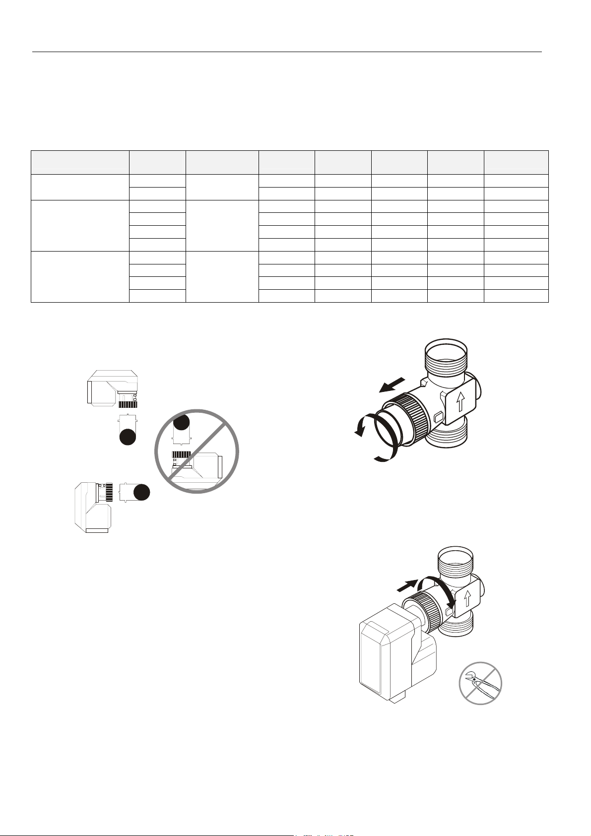
MOUNTING POSITION
The actuator may only be mounted beside or above the valve.
Adjust the valve to the correct position before mounting the
actuator.
aux. switch
S1
300 N -- -- B M7410C1015
300 N -- -- C M6410L2031
300 N X X C M6410L4037
aux. switch
S2
housing
type
OS number
Fig. 1. Mounting positions
MOUNTING
Before the actuator is fixed to the valve, you must remove the
adjustment cap (Fig. 2). Make sure that the actuator is in the
retract position (factory-supplied position) before fixing the
actuator to the valve body.
EN0B-0096GE51 R0909
Fig. 2. Remove protection cap
The actuator must be mounted by hand. Do not use tools or
additional force as this may damaged actuator and valve.
Fig. 3. Mounting the actuator
2
Page 3

M6410C/L, M7410C Small 3-Position Linear Valve Actuators
A
A
ABABA
ABA
A
ELECTRIC WIRING OF MOTOR
A fuse with a contact gap of at least 3 mm for each pole must
be fitted with the fixed installation. The fuse rate is max. 2 A.
The electrical installation must comply with the wiring diagram
shown in Fig. 4.
COM
WHITE
N
BLUE
DN15
-
DN20
DN25
-
DN40
DN15
-
DN40
DN15
-
DN20
CABLE COLORS FOR 24-V MODELS (M6410C, M7410C)
GREEN
CABLE COLORS FOR 230-V MODELS (M6410L)
BLACK
WORKING OPERATION PORT A
AB
A B
A
B
A
B
Fig. 4. Electric wiring of motor
230 Vac: L 2A, VDE 0641, IEC 269
M
BROWN
BROWN
closingopening
closing
opening
closing
opening
B
closing
opening
B
B
B
B
COMMISSIONING ADVICE
A functional check of the valve actuator can be carried out by
changing the controller setpoint by 5 °C or more. The movement of the actuator stem (Fig. 6) indicates whether the valve
is opening or closing.
17.8 mm
11.7 mm
Fig. 6. Movement of the actuator stem
AUXILIARY SWITCHES
The actuators with the OS-number M*****40** feature two
auxiliary switches, each with its own cable. Auxiliary switch S1
switches when the stem reaches its fixed
Auxiliary switch S2 switches when the stem reaches its
adjustable
switchpoint.
Fig. 7. Auxiliary switch cables
Adjustment of Auxiliary Switch 2
Auxiliary switch 2 should be adjusted by a skilled person,
only.
Move the actuator to the position where the switch is to be
tripped. Cut the plastic skin with a sharp knife. Below the skin,
the adjustment screw can be accessed. Turn the screw
clockwise until the end stop is reached. Turn the screw
counterclockwise until the switch point is achieved. To check
that the required position has been set, move the actuator.
Finally, seal the adjustment hole with a piece of tape.
switchpoint.
a
b
c
a
b
c
MANUAL OPERATION
The actuators with integrated manual operation (see Table 1)
feature a hexagonal key hole for manual operation. For more
comfort, an additional knob for manual adjustment is packed
separately. To avoid damaging the valve, separate the
actuator from the power supply before adjusting manually.
Fig. 8. Adjustment of auxiliary switch S2
Electric Wiring of Auxiliary Switches
4 mm
Fig. 5. Manual operation
The electrical installation must comply with the wiring diagram
shown in Fig. 9. If the auxiliary switch is connected to
230 Vac, a switch with a contact gap of at least 3 mm for each
pole must be fitted with the installation.
3
EN0B-0096GE51 R0909
Page 4

M6410C/L, M7410C Small 3-Position Linear Valve Actuators
(1)
M6410C/L
M7410E
A
A B
AB
AB
A
A
BLUE
DN15
-
DN20
DN25
-
DN40
DN15
-
DN40
DN15
-
DN20
S1
S2
(230 Vac, only):
open
AB AB AB
close
A B A B
close
A
AB A
B
close
A
AB A
B
BROWN
BLUE
BLACK
BROWN
BLACKBLUE
24 Vac: max. 100 mA
230 Vac: max. 5
BLUE
B
B
BROWN
BLACK
BROWN
BLACKBLUE
Fig. 9. Electric wiring of auxiliary switch
Application Example: Switching Off an
Electrical Appliance
2-Way-Valve
DN 15, DN 20
B
B
BROWN
BLACK
BROWN
BLACKBLUE
All Other Valves
DN 15 - DN 40 DN 25 - DN 40DN 15 - DN 20
close
open
open
AB
open
AB
Fig. 11. Application example of auxiliary switch
E. g. fan, pump etc.
max. 5 (1)A
BLUE
BLACK
DIMENSIONS (MM)
58
80
49
60
100
housing type ‘A’
49
82
housing type ‘B’
58
60
109
E. g. fan, pump etc.
BLUE
87
housing type ‘C’
max. 5 (1)A
Fig. 10. Application example of auxiliary switch
BLACK
Fig. 13. Housing types
Manufactured for and on behalf of the Environmental and Combustion Controls Division of Honeywell Technologies Sàrl, Rolle, Z.A. La Pièce 16, Switzerland by its Authorized Representative:
Automation and Control Solutions
Honeywell GmbH
Böblinger Strasse 17
71101 Schönaich / Germany
Phone: (49) 7031 63701
Fax: (49) 7031 637493
http://ecc.emea.honeywell.com
Subject to change without notice. Printed in Germany
EN0B-0096GE51 R0909
 Loading...