

Page 1

APPLICATION
The Series 72 Modutrol IV Motors are used to control
dampers and valves. The motors accept a current or voltage
signal from an electronic controller to position a damper or
valve at any point between open and closed.
Series 72
Modutrol IV™ Motors
PRODUCT DATA
FEATURES
• Replaces M744S,T,Y and M745S,T,Y Motors.
• M7261, M7274, M7281, M7284, and M7294 are
non-spring return motors; M7272, M7282, M7285,
and M7286 are spring return motors.
• Oil immersed motor and gear train for reliable
performance and long life.
• Wiring box provides NEMA 3 weather protection.
• Actuator motor and circuitry operate from 24 Vac.
Models available with factory installed transformer
or an internal transformer can be field added.
• Quick connect terminals standard—screw terminal
adapter available.
• Adapter bracket for matching shaft height of older
motors is standard with replacement motors.
• Nominal timing of 30 seconds for 90° stroke and
60 seconds for 160° stroke.
• Valve and damper linkages, explosion-proof housing,
and auxiliary switches available as accessories.
• Spring return motors are rated for 25 lb.-in. and
60 lb.-in torque.
• Non-spring return motors are rated for 35 lb.-in.,
75 lb.-in., 150 lb.-in., and 300 lb.-in. torque.
• Models available with adjustable start (zero) and span.
• Models available with 4 to 20 mA input signal.
• Models available with 2 to 10 Vdc input signal.
• Die-cast aluminum housing.
® U.S. Registered Trademark
Copyright © 2000 Honeywell • All Rights Reserved
Application ........................................................................ 1
Features ........................................................................... 1
Specifications ................................................................... 2
Ordering Information ........................................................ 2
Installation ........................................................................ 5
Settings and Adjustments ................................................. 10
Operation and Checkout .................................................. 12
®
Contents
63- 2202-4
Page 2
SERIES 72 MODUTROL IV™ MOTORS
SPECIFICATIONS
Models:
provide ease of stocking, ease of handling and maximum
replacement value. TRADELINE model specifications are the
same as those of st andard model s unless sp ecified ot herwise.
TRADELINE models have auxiliary switch cams.
NOTE: Auxiliary switches can only be added to motors that
M
TRADELINE models are selected and packaged to
include auxiliary switch cams. (These cams cannot
be field-added.)
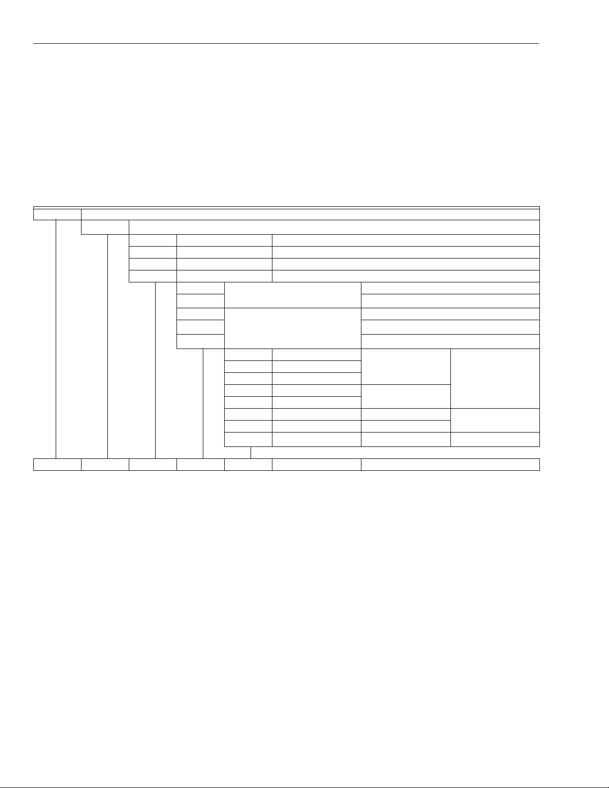
Table 1. Modutrol IV Order Number Guide.
Motor
72
4-20 mA or 2-10 Vdc Control
6
7
8
9
— 35 lb-in. Non-Spring Return
25 lb-in. Spring Return 75 lb-in. Non-Spring Return
60 lb-in. Spring Return 150 lb-in. Non-Spring Return
— 300 lb-in. Non-Spring Return
1
a
Single-ended shaft Non-Spring Return
2
4
Dual-ended shaft Non-Spring Return
5
6
A
B
C
D
F
G
L
Q
IMPORTANT
The specifications given in this publication do not
include normal manufa cturin g tolera nces. Therefor e,
an individual unit may not exactly match the listed
specifications. Also, this product is tested and
calibrated under closely controlled conditions and
some minor differences in performance can be
expected if those conditions are cha nged.
Modutrol IV Order Number Guide:
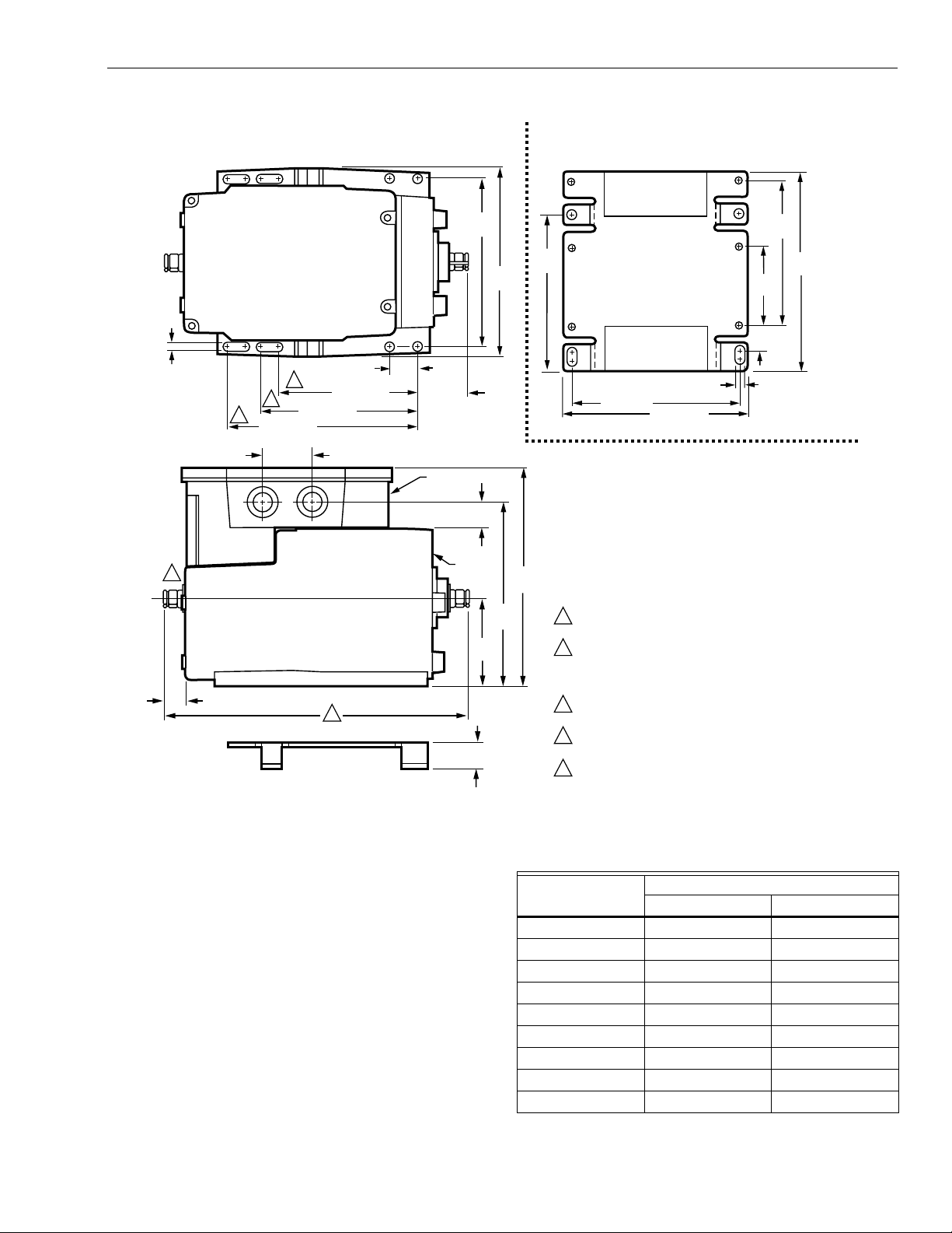
Dimensions:
See Fig. 1.
Normally Closed
Normally Closed
Normally Openc Spring Return
0 Auxiliary Switches Fixed Stroke
1 Auxiliary Switch
2 Auxiliary Switches
0 Auxiliary Switch Adjustable Stroke
2 Auxiliary Switches
0 Auxiliary Switch Fixed Stroke
1 Auxiliary Switch Adjustable Stroke
2 Auxiliary Switches Fixed Stroke
See Table 1.
b
Spring Return
b
Spring Return
Normally Closed
Normally Open
Normally Closed
b
c
b
M6184AXXXX
a
Adjustable zero and span.
b
Electrically normally clos ed. Shaf t rotates clock wise (v iewed fro m the powe r end) wit h incre ase i n control s ignal . Moto r drives to
See Catalog for Complete O.S. Number
normally closed positi on when power ed with control wiring not connected.
c
Electrically normally open. Shaft rotates counterclockwise (viewed from the power end) with increase in control signal. Motor
drives to normally open position when powered with control wiring not connected.
ORDERING INFORMATION
When purchasing replacement and modernization products from your TRADELINE® wholesaler or distributor, refer to the
TRADELINE® Catalog or price sheets for complete ordering number.
If you have additional questions, need further information, or would like to comment on our products or services, please write or
phone:
1.
Your local Home and Building Control Sales Office (check white pages of your phone directory).
2.
Home and Building Control Customer Relations
Honeywell, 1885 Douglas Drive North
Minneapolis, Minnesota 55422-4386
In Canada—Honeywell Limited/Honeywell Limitée, 35 Dynamic Drive, Scarborough, Ontario M1V 4Z9.
International Sales and Service Offices in all principal cities of the world. Manufacturing in Australia, Canada, Finland, France,
Germany, Japan, Mexico, Netherlands, Spain, Taiwan, United Kingdom, U.S.A.
63-2202—42
Page 3
SERIES 72 MODUTROL IV™ MOTORS
TOP VIEW OF BRACKET TOP VIEW
1/4
(7)
1
AUXILARY
END
9/16 (15)
ADAPTER
BRACKET
5
3
4
4-1/16 (103)
1-1/2 (37)
4-1/16 (103)
4-1/16 (103)
2
13/16
(20)
POWER
END
1-1/2 (37)
WIRING
BOX
4-7/8
(124)
3/4
(19)
MOTOR
2-9/16
(66)
3/4
(19)
5-1/2
(140)
5-3/8
(137)
6-7/16
(164)
4-5/8
(116)
11/16
POWER END
1/4 (7)
4-7/8 (124)
5-9/16 (141)
SPRING RETURN MODEL SHOWN
SOME MODELS DO NOT HAVE AN AUXILIARY
1
SHAFT. ALL OTHER DIMENSIONS ARE THE SAME.
2
FOR HIGH TORQUE (60 LB-IN.) SPRING RETURN
MODELS 8-3/4 (222); FOR LOW TORQUE (25 LB-IN.)
SPRING RETURN MODELS 8-1/4 (210);
NON-SPRING RETURN MODELS 7-5/16 (185).
FOR HIGH TORQUE (60 LB-IN.) SPRING
3
RETURN MODELS (SHOWN).
4
FOR LOW TORQUE (25 LB-IN.) SPRING
RETURN MODELS.
5
FOR NON-SPRING RETURN MODELS.
2-5/16
(58)
(17)
4-1/4
(107)
5-13/16
(148)
M17089BB
Fig. 1. Series 72 Modutrol IV Motor dimensions in in. (mm).
Controller:
These motors can be used with any electronic
controller that provides a stable noise-free proportional
current output as specified in Electrical Ratings, Input
Range below.
Electrical Ratings:
Power Consumption: See Table 2.
Input Range:
Current, Nonadjustable: 4 to 20 mA nominal, 25 mA
maximum.
Current, Adjustable: 4 to 20 mA adjustable, 50 mA
maximum.
Zero/Null (Motor Closed): 0.08 to 18 mA.
Span: 1.8 to 18 mA.
Voltage, Nonadjustable: 2 to 10 Vdc.
Input Impedance:
4 to 20 mA Input: 100 ohms.
2 to 10 Vdc Input: 400K ohms.
Table 2. Series 72 Modutrol IV Motor Power
Consumption Ratings (at 120 Vac, 50/60 Hz).
Power Consumption
Model
Watts Amps
M7261 19 0.20
M7272 26 0.26
M7274 15 0.71
M7281 23 0.24
M7282 28 0.28
M7284 23 0.24
M7285 28 0.28
M7286 23 1.00
M7294 23 0.24
3 63-2202—4
Page 4

SERIES 72 MODUTROL IV™ MOTORS
Auxiliary Switch Ratings (in Amps):
See Table 3.
Table 3. Auxiliary Switch Ratings (in Amps).
One Contact
Rating
a
120V 240V
Full Load 7.2 3.6
Locked Rotor 43.2 21.6
a
40 VA pilot duty, 120/240 Vac on opposite contact.
Stroke:
Fixed 90° or 160° models available. Other models
available with field adjustable strokes from 90° to 160°.
Stroke adjusted by means of cams located in the wiring
compartment.
Timing:
Nominal 30 seconds for 90° stroke and 60 seconds
for 160° stroke.
Dead Weight Load On Shaft:
200 lb (91 kg) on motor power
or auxiliary end; maximum combined load of 300 lb (136 kg).
Motor Rotation:
Closed: Counterclockwise rotation limit as viewed from motor
power end.
Open: Clockwise rotation limit as viewed from motor power
end.
Mechanically Normal ly Closed: Sprin g return. Normally clo sed
motors rotate to closed position on power loss.
Mechanically Normally Open: Spring return. Normally open
motors rotate to open position on power loss.
Electrically Normally Closed: Both spring return and non-
spring motors return to closed position on minimum signal.
Electrically Normall y Op en: Both sp rin g re turn an d n on-s pri ng
return motors return to open position on minimum signal.
Ambient Temperature Ratings:
Shaft:
3/8 in. [9.5 mm] square.
-40 to 150°F (-40 to 66°C).
Approvals:
Underwriters Laboratories Inc. Listed: File No. E4436; Guide
No. XAPX.
Canadian Standards As soc ia tio n Certi fied: General listed File
No. LR1620; Guide No. 400-E.
Accessories:
198162AA Internal Transformer 120/208/240 Vac 50/60 Hz
primary, 24 Vac secondary.
198162EA Internal Transformer; 120 Vac 50/60 Hz primary,
24 Vac sec ond ary.
198162GA Internal Transformer; 220 Vac 50/60 Hz primary,
24 Vac sec ond ary.
198162JA Internal Transformer; 24 Vac 50/60 Hz primary,
24 Vac secondary (for electrical isolation).
220736A Internal Auxiliary Switch Kit; one switch, can be
field-installed on TRADELINE models.
220736B Internal Auxiliary Switch Kit; two switches, can be
field-installed on TRADELINE models.
220738A Adapter Bracke t rais es m otor shaf t heig ht by 19 mm
to match that of previous Modutrol
®
Motor models.
220741A Screw Terminal Adapter converts the standard
quick-connect terminals to screw terminals.
221455A Infinitely Adjustable Crank Arm, can rotate through
downward position and clear motor base without requiring
an adapter bracket.
4074ERU Weatherproofing Kit provides NEMA 3 rating for
Modutrol IV Motors mounted in position other than upright.
4074EZE Bag Assembly with parts that can provide CE
compliance.
7617ADW Crank Arm, can rotate through downward position
and clear motor base without requiring an adapter bracket.
ES650-117 Explosion-Proof Housing encloses motor for use
in explosive atmospheres. Not for use with Q5001 (or any
other valve linkages). Order separately from O-Z/Gedney
Inc. T o order , contac t: O-Z/Gedney, Nelson Enclosures and
Controls,
(918) 641-7381 or (918) 641-7374; or write to:
O-Z/Gedney, Nelson Enclosures and Controls
P.O. Box 471650
Tulsa, OK 74147-1 65 0
(Requires Honeywell 7617DM Coupling.)
Q100 Linkage connects Modu trol
®
Motor to V51 Butterfly
Valve. Requires the 220738A Adapter Bracket.
Q181 Auxiliary Potentiometer for sequence or unison control
of 1 to 4 additional modulating (Series 90) motors.
Q5001 Bracket and Linkage Assembly connects Modutrol IV
Motor to water or steam valve.
Q605 Damper Linkage connects motor to damper. Includes
motor crank arm.
Q607 External Auxiliary Switch controls auxiliary equipment
as a function of motor position.
63-2202—44
Page 5

INSTALLATION
FULLY OPEN
90 DEGREE STROKE
160 DEGREE STROKE
M5509
VERTICAL
REFERENCE
FULLY CLOSED
160
10
VERTICAL
REFERENCE
FULLY CLOSED
90
10
FULLY OPEN
VERTICAL
REFERENCE
VERTICAL
REFERENCE
FULLY CLOSED
FULLY OPEN
FULLY
CLOSED
FULLY
OPEN
90 DEGREE STROKE 160 DEGREE STROKE
NON-SPRING RETURN MOTORS
160
10
90
45
SPRING RETURN MOTORS
M7272, M7282, M7285, M7286
M7261, M7274, M7281, M7284, M7294
SERIES 72 MODUTROL IV™ MOTORS
When Installing this Product...
1.
Read these instructio ns c aref ull y. Failure to follow them
could damage the product or cause a hazardous
condition.
2.
Check the ratings given in the instructions and on the
product to make sure the product is suitable for your
application.
3.
Installer must be a trained, experienced service
technician.
4.
After installation is complete, check out product
operation as provided in these instructions.
CAUTION
Electrical Shock or Equipment Damage Hazard.
Can shock individuals or short equipment
circuitry.
Disconnect all power supplies before installation.
Motors with auxiliary switches can have more than
one disconnect.
CAUTION
Equipment Damage Hazard.
Can damage the motor beyond repair.
Never turn the motor shaft by hand or with a wrench.
Forcibly turning the motor shaft damages the gear
train and stroke limit contacts.
IMPORTANT
Always conduct a thorough checkout when
installation is complete.
Mounting
Use the following guidelines for proper motor mounting:
• Always install motors with the crankshaft horizon tal.
• Mounting flanges extending from motor housing base are
drilled for 1/4 inch (6.4 mm) machine screws or bolts.
• Non-Spring Return Motors are shipped from the factory in
the closed position (at the counterclockwise rotation limit,
as viewed from the motor power end).
• Spring Return Motors are shipped from the factory in their
normal position.
• Normally closed models are shipped at the counterclockwise
rotation limit, as viewed from the motor power end.
• Normally open models are shipped at the clockwise
rotation limit, as viewed from the motor power end.
Location
Allow enough clearance for accessory installation and motor
servicing when selecting a location (see Fig. 1). If located
outdoors, use liquid-tight conduit connectors with the junction
box to provide NEMA 3 weather protection. If mounted
outdoors in a position other than upright, install a 4074ERU
Weatherproofing Kit and liquid-tight connectors to provide
NEMA 3 protection.
CAUTION
Motor Damage Hazard.
Deteriorating vapors and acid fumes can damage
metal parts.
Install motor in areas free of acid fumes and other
deteriorating vapors.
In excessive salt environments, mounting base and screws
should be zinc or cadmiu m plated, not stai nless steel or bra ss.
Use the 220738A Adapter Bracket for mounting on these
surfaces.
Fig. 2. Motor shaft position at limit of rotation
(viewed from motor power end).
5 63-2202—4
Page 6

SERIES 72 MODUTROL IV™ MOTORS
Adapter Bracket
The 220738A Adapter Brack et , pos iti one d be tw een the motor
and the equipment, raises motor shaft height by 0.75 in.
(19 mm) to match that of previous Modutrol
The following applications require this bracket:
• Q607 External Auxiliary Switch.
• Damper linkage applications requiring added clearance to
allow:
— Crank arm rotation through the downward position.
— Sufficient damper linkage to reach the motor shaft.
• All valve linkages except the Q5 001 .
NOTE: When the bracket is not used in a replacement
application, the damper linkage requires adjustment
for the new shaft position.
To mount the motor with the bracket:
1.
Mount the bracket to the equipment with existing or
standard bolts.
2.
Using the provided b olts, mount t he motor to the br acket
threaded holes. See Fig. 3.
For valve linkage applications (other than the Q5001):
1.
Mount the bracket to the linkage.
2.
Position the motor on the bracket to align the motor
shaft with the linkage.
3.
Attach the motor to the bracket with the four bolts
provided. See Fig. 4.
®
Motor models.
Damper Linkages
The motor does not inc lud e a c ran k arm . O rde r the c r an k ar m
separately (see Ac cessories in the Specifi cations se ction). For
detailed instructions on the assembly of specific linkages,
refer to the Installation Instructions packed with the linkage.
CAUTION
Equipment Damage Hazard.
Stalling a motor can damage the drive shaft.
Ensure installation of motors and linkages allows the
motor to drive through full stroke without obstruction.
Valve Linkages
The Q100 Linkage requires a 220 738A Adapter Brac ket for all
valve application s. Applicat ions with the Q 5001 Valve Linkage
do not require the 220738A Adapter Bracket (see Fig. 4).
For detailed instructions on specific linkage assemblies, refer
to the instruction sheet packed with the linkage. In general,
check the following points whe n inst alling a moto r and l inkag e:
• Adjust valve and louver-type damper linkages so the
damper or valve moves through only the maximum required
distance while the motor moves through its full stroke.
• With modulating cont rol, maximum dam per opening sh ould
be no more than 60 degrees. Little additional airflow is
provided beyond this point.
• Do not exceed load and torque ratings in any application.
Junction Box
When used with liquid-tight conduit connectors, the junction
box provides NEMA 3 weather protection for the motor. The
junction box, standard w ith repl ac eme nt m oto rs, e ncl os es the
terminals and provid es knoc kouts fo r wiring co nduits. H ousing
an internal transformer or internal auxiliary switches requires
using a junction box.
63-2202—46
Page 7

STANDARD
BOLTS (4)
1
POWER END
EQUIPMENT
BASE
No. 12 OR 1/4 in. ZINC PLATED
1
MACHINE SCREWS OR BOLTS
ADAPTER
BRACKET
POWER END
BOLTS
PROVIDED (4)
WIRING
BOX
MOTOR
SERIES 72 MODUTROL IV™ MOTORS
POWER END
Q5001
VALVE
LINKAGE
M452E
POWER
END OF
MOTOR
NON-SPRING RETURN
Fig. 3. Mounting the motor with an adapter bracket.
WIRING
BOX
MOTOR
1/4-20 UNC
1 in. LONG
MOUNTING
VALVE
BOLTS
M17092
SPRING RETURN
Fig. 4. Mounting the motor on a Q5001 Valve Linkage.
7 63-2202—4
Page 8

SERIES 72 MODUTROL IV™ MOTORS
Wiring
CAUTION
Electrical Shock or Equipment Damage Hazard.
Can shock individuals or short equipment circuitry.
Disconnect all power supplies before installation.
Motors with auxiliary switches can have more than
one disconnect.
IMPORTANT
All wiring must agree with applicable codes,
ordinances and regulations.
1.
Ensure that the voltage and frequency stamped on the
motor correspond with the power supply characteristics.
2.
When connecting sev eral motors in p arallel, en sure that
the power supply VA rating is large enough to provide
power to all motors used without overloading.
3.
Fig. 5 shows that motor terminals are quick-connects
located on top of the printed circuit board.
4.
To access the wiring compartment:
a. Remove the four screws from the junction box top.
b. Lift off the cover.
5.
Fig. 6 shows the internal wiring schematic.
6.
Refer to Fig. 7 and 8 for typical wiring.
Wire the motor as follows:
1.
Remove the wiring box cover by removing the four
screws holding the cover to the motor.
2.
Wire motor to system using quick-connect terminals in
wiring box.
3.
Replace wiring box cover.
A
RIGHT/INNER
AUXILIARY
SWITCH
F (TEST)
V(-)
Y(+)
T2
T1
NOTE: FEATURES AVAILABLE ON SOME MODELS ONLY.
2 TO 10 VDC INPUT MOTORS 4 TO 20 mA NONADJUSTABLE INPUT MOTORS
INNER AUXILIARY
SWITCH CAM (BLUE)
POWER
END
OUTER AUXILIARY
SWITCH CAM (RED)
LEFT/OUTER
AUXILIARY
SWITCH
NOTE: FEATURES AVAILABLE ON SOME MODELS ONLY.
B
NOTE: FEATURES AVAILABLE ON SOME MODELS ONLY.
C
(+)
F
SPAN ADJUST
MIN MAX
(–)
T2
START ADJUST
T1
4 TO 20 mA ADJUSTABLE INPUT MOTORS
MIN MAX
START ADJUST POTENTIOMETER
(+)
F
(-)
T2
T1
SPAN ADJUST
POTENTIOMETER
RIGHT/INNER
AUXILIARY
SWITCH
INNER AUXILIARY
SWITCH CAM (BLUE)
OUTER AUXILIARY
SWITCH CAM (RED)
LEFT/OUTER
AUXILIARY
SWITCH
POWER
END
RIGHT/INNER
AUXILIARY
SWITCH
INNER AUXILIARY
SWITCH CAM (BLUE)
POWER
END
OUTER AUXILIARY
SWITCH CAM (RED)
LEFT/OUTER
AUXILIARY
SWITCH
M5777
Fig. 5. Terminals and adjustments.
63-2202—48
Page 9

SERIES 72 MODUTROL IV™ MOTORS
–+ F
T2
BRAKE
ELECTRONIC
CIRCUIT
TRIAC
SWITCHING
FEEDBACK
POTENTIOMETER
CLOSE
LIMIT
CCW
WINDING
(CLOSE)
1
2
3
4
2
POWER SUPPLY. PROVIDE DISCONNECT MEANS AND
OVERLOAD PROTECTION AS REQUIRED.
DIRECTION OF MOTOR TRAVEL AS VIEWED FROM POWER END.
INTERNALLY MOUNTED TRANSFORMER. DO NOT CONNECT
POWER SUPPLY TO T1 AND T2.
BRAKE CIRCUITRY ONLY ON SPRING RETURN MODELS.
TRIAC
SWITCHING
OPEN
LIMIT
CW
WINDING
(OPEN)
2
CIRCUITRY
4
3
T1
Fig. 6. Series 72 motor internal wiring schematic.
M5511
1
L1
(HOT)
L2
MOTOR
CONTROLLER
-
+
POWER SUPPLY. PROVIDE DISCONNECT MEANS AND
1
OVERLOAD PROTECTION AS REQURED.
CONNECTING F TO
2
T1
T2
24V
-
+
2
F
– WILL DRIVE MOTOR TO FULLY OPEN.
Fig. 7. Typical system wiring.
-20 mA
ONTROLLER
-
+
MOTOR
-
+
F
MOTOR
-
+
F
MOTOR
-
+
F
T1
T2
2
T1
T2
2
T1
T2
2
1
L1
(HOT)
L1
(HOT)
L2
L2
M5778
1
POWER SUPPLY. PROVIDE DISCONNECT MEANS AND
1
OVERLOAD PROTECTION AS REQURED.
CONNECTING F TO
2
– WILL DRIVE MOTOR TO FULLY OPEN.
M5774
Fig. 8. Driving up to six motors from
one 4 to 20 mA controller.
9 63-2202—4
Page 10

SERIES 72 MODUTROL IV™ MOTORS
SETTINGS AND ADJUSTMENTS
Zero and Span Adjustment for M7284Q and M7285Q Motors (Fig. 5.)
1.
Adjust the start potentiometer fully clockwise (maximum
zero) and the span p otentio meter full y counte rclockw ise
(minimum span).
2.
Set the controller current to the value required to drive
the motor to the closed position.
3.
Turn the start potentiometer slowly counterclockwise
until the motor begins to open. This is defined as the
start or zero setting.
4.
Set the controller current to the value required to drive
the motor to the fully open positi on. The motor wi ll open.
5.
Turn the span potentiometer clockwise until the motor
starts to close. The difference between the fully open
span position current and the zero position current is
defined as the operating span.
6.
Recheck the start and readjust the span potentiometer
P1 if necessary. Turn the start potentiometer clockwise
to increase the zero position.
7.
Recheck the span and readjust the span potentiometer
if necessary. Turn it clockwise to increase the full span
position.
8.
For sequential operation, as shown in Fig. 9, repeat the
above steps for each motor.
FOR ADJUSTABLE ZERO AND SPAN MODELS
20
(10)
16
(8)
12
(6)
8
(4)
CONTROL OUTPUT
mA CURRENT (OR VOLTS DC)
4
(2)
SEQUENTIAL OPERATION
Auxiliary Switches
CAUTION
Electrical Shock or Equipment Damage Hazard.
Can shock individuals or short equipment
circuitry.
Disconnect all power supplies before installation.
Motors with auxiliary switches can have more than
one disconnect.
CAUTION
Equipment Damage Hazard.
Can damage the motor beyond repair.
Never turn the motor shaft by hand or with a wrench.
Forcibly turning the motor shaft damages the gear
train and stroke limit contacts.
Adjustable cams actuate the auxiliary switches. These cams
can be set to actuate the switches at any angle within the
motor stroke. Select switch differential of 1° or 10°.
Motors with factory added auxiliary switches are shipped in
the closed position (fully counterclockwise, as viewed from the
motor power end) with auxiliary cams set to actuate switches
30° from the closed position and to provide 1° degree
differential. With the motor in the closed (fully
counterclockwise) position, the auxiliary switch breaks
contacts R-B. See Fig. 10 for auxiliary switch wiring.
TRADELINE Motors are shipped with auxiliary switch cams
that permit acceptance of 220 736A,B Interna l Auxiliary Switc h
Kits. Refer to form 63-2228 for 220736A,B Installation
Instructions.
0
CLOSED
MOTOR 1 PROPORTIONS BETWEEN 4 AND 12 mA; FULLY
1
CLOSED AT 4 mA, FULLY OPENED AT 12 mA.
MOTOR 2 PROPORTIONS BETWEEN 8 AND 16 mA; FULLY
CLOSED AT 8 mA, FULLY OPENED AT 16 mA.
MOTOR 3 PROPORTIONS BETWEEN 12 AND 20 mA SIGNAL;
FULLY CLOSED AT 12 mA, FULLY OPENED AT 20 mA.
UP TO 6 MOTORS CAN BE DRIVEN SEQUENTIALY OR IN
2
UNISON FROM ONE CONTROLLER.
ADJUST ZERO ADJUST AND SPAN ADJUST POTENTIOMETERS
3
TO ACHIEVE DESIRED SEQUENCE.
OPEN
MOTOR 1 MOTOR 2 MOTOR 3
1 3 3 3
CLOSED
OPEN
CLOSED OPEN
M2893A
2
Fig. 9. Sequential operation of motors.
63-2202—410
Page 11

Auxiliary Switch Adjustment
SERIES 72 MODUTROL IV™ MOTORS
IMPORTANT
When adjusting the auxiliary switch cams use the
following procedure:
1.Insert 1/8 in. screwdriver blade into a slot on cam
and move the screwdriv er top as far as pos sible in
the required direction. See Fig. 10.
2.Repeat step 1 in successive cam slots until the
cam is in the required position.
Use the following procedure to obtain the desired auxiliary
switch settings:
1.
Remove the top cover from the motor to gain access
to the motor terminals and auxiliary cams.
2.
Disconnect the controller from the motor.
3.
Connect a current source to the positive and negative
terminals.
4.
Drive the motor to the position where the auxiliary
equipment is to be switched by in creasing or de creasing
the current.
5.
For a switch differential of 1°, check continuity of auxiliary
switch contacts R-B and rotate the cam as follows:
a. If the contacts are open, rotate the cam clockwise
until the R-B contacts close.
b. If the contacts are closed, rotate the cam
counterclockwise until the R-B contacts open.
MOVE SCREWDRIVER AT
TOP ONLY TO ADJUST CAM.
1/8 INCH
STRAIGHT-BLADE
SCREWDRIVER
6.
For a switch differential of 10° rotate the cam
approximately 180° so the slow-rise portion of the
cam actuates the switch.
7.
Check continuity of the auxiliary switch contacts R-B.
8.
Rotate the cam as follows:
a. If the contacts are open, rotate the cam
counterclockwise until the R-B contacts close.
b. If the contacts are closed, rotate the cam clockwise
until the R-B contacts open.
c. Make final adjustment in the proper direction to
obtain contact make or break at the desired position.
9.
Check for the proper differential and switching of the
auxiliary equipment by driving the motor though the full
stroke in both directions.
10.
Disconnect power, remove current source, reconnect
the controller, and replace the top cover on the motor.
NOTE: Changing the differential from 1° to 10° reverses the
switching action. For exa mple, with a 10° dif fer ential,
switch contacts R-B make and R-W break on a
counterclockwise (closed) rotation. With a 1°
differential, switch contacts R-W make and R-B
break on a counterclockwise (closed) rotation.
NOTE: CAMS ARE OFFSET
VERTICALLY TO PROVIDE
BETTER VIEW OF BACK CAM.
SLOW RISE
PORTION
(APPROX.
10° DIFF.)
LEFT/OUTER
AUXILIARY
SWITCH
FAST RISE
PORTION
(APPROX.
1° DIFF.)
MOTOR
OPEN
INNER
AUXILIARY
CAM
(BLUE)
OUTER
AUXILIARY
CAM
(RED)
POWER
END
RIGHT/INNER
AUXILIARY
SWITCH
FAST RISE
PORTION
(APPROX.
1° DIFF.)
SLOW RISE
PORTION
(APPROX.
10° DIFF.)
MOTOR
CLOSE
LEFT/OUTER
AUXILIARY
SWITCH
POWER END
OF MOTOR
Fig. 10. Auxiliary switch adjustment.
RIGHT/INNER
AUXILIARY SWITCH
INNER AUXILIARY
CAM (BLUE)
OUTER AUXILIARY
CAM (RED)
M17101
11 63-2202—4
Page 12

Printed in U.S.A. on recycled
paper containing at least 10%
post-consumer paper fibers.
SERIES 72 MODUTROL IV™ MOTORS
OPERATION AND CHECKOUT
Operation
The motor feedback potentiometer and control current input
circuit form a bridge circuit. As long as the final control
element remains at the position proportional to the input
current from the controller, the circuit is balanced, and the
motor does not run. When the value of the controlled medium
changes, the current from the controller changes, and
unbalance is amplified to energize the Triac switching to run
the motor in the proper direction to correct the change in the
temperature or the pressure. The motor turns the feedback
potentiometer to rebalance the circuit and stop the motor.
Checkout
After installation and linkage adjustment, operate the motor
through the controller. Make sure that:
• The motor properly operates the damper or valve.
• The motor responds properly as the input is varied.
• The auxiliary switch, if used, operates at the desired point
of motor rotation.
Inspect the motor, linkage, and valve or damper to see that all
mechanical connections are correct and secure.
In damper installations, the pushrod should not extend more
than a few inches past the ball joints. Check to see that
there is adequate clearance for the linkage to move through
its stroke without binding or striking other objects.
See controller or system instructions for additional checkout
procedures.
Motor Operation Checkout
Check motor operation as follows:
1.
To close the motor, open terminals +, -, and F.
2.
To open the motor, connect terminal F to the
negative (-) motor terminal.
Home and Building Control Home and Building Control Honeywell Asia Pacific Inc. Honeywell Europe S.A. Honeywell Latin American
Honeywell Honeywell Limited-Honeywell Limitée Room 3213-3225 3 Avenue du Bourget Region
1985 Douglas Drive North 35 Dynamic Drive Sun Hung Kai Centre 1140 Brussels 480 Sawgr ass Corporate Parkway
Golden Valley, MN 55422 Scarborough, Ontario No. 30 Harbour Road Belgium Suite 200
63-2202—4 B.B. Rev. 11-00 www.honeywell.com
M1V 4Z9 Wanchai Sunrise FL 33325
Hong Kong
 Loading...