

Honeywell M6284D1026, M6284D4004, M6284D1000, M6284F1070, M6285A1005 Series Manual
...
Series 61 and Series 62
Modutrol IV™ Motors
FEATURES
• Replaces M644, M944B,E,G,H,J,K,R,S and
• Integral junction box provides NEMA 3 weather
• Integral spring return returns motor to normal position
• Motor and circuitry operate from 24 Vac. Models
• Quick-connect terminals are standard—screw terminal
• Adapter bracket for matching shaft height of older
• Motors have field adjustable stroke (90° to 160°).
• Die-cast aluminum housing.
• Integral auxiliary switches are available factory
APPLICATION
The Series 61 and Series 62 Modutrol IV™ Motors are
three-wire spring return and non-spring return floating control
motors. Use these motors with controllers that provide a
switched spdt or floating output to operate dampers or valves.
The Series 62 motors have an internal electrically isolated
feedback potentiometer that provides indication of the motor
shaft position and can be used for slaving Series 90 Motors or
rebalancing an external control circuit.
• Nominal timing standard of 30 seconds (90° stroke),
• Spring return motors can operate valve linkages from
• All models have dual shafts (slotted and tapped on
• All models have auxiliary switch cams.
• Fixed torque throughout the entire voltage range.
• Motors are designed for either normally open or
• Series 62 models include electrically isolated feedback
• Series 62 TRADELINE models have linear feedback,
PRODUCT DATA
M945B,C,G,K,L,AD Motors.
protection.
when power is interrupted.
available with factory installed transformer, or a field
added internal transformer.
adapter is available.
motors is available.
mounted, or can be field added.
and 60 seconds (160° stroke). Other timings available.
power end or auxiliary end shafts for normally closed
or normally open valve applications.
both ends).
normally closed valves and dampers.
potentiometer that provides shaft position indication.
configurable for slaving Series 90 Motors.
Contents
Application ........................................................................ 1
Features ........................................................................... 1
Specifications ................................................................... 2
Ordering Information ........................................................ 2
Installation ........................................................................ 4
Settings and Adjustments ................................................. 7
Operation .......................................................................... 10
Checkout .......................................................................... 10
Replacement .................................................................... 10
63-2629—2
SERIES 61 AND SERIES 62 MODUTROL IV™ MOTORS
SPECIFICATIONS
Models: TRADELINE models are selected and packaged to
provide ease of stocking, ease of handling and maximum
replacement value. TRADELINE model specifications are the
same as those of standard models unless specified otherwise.
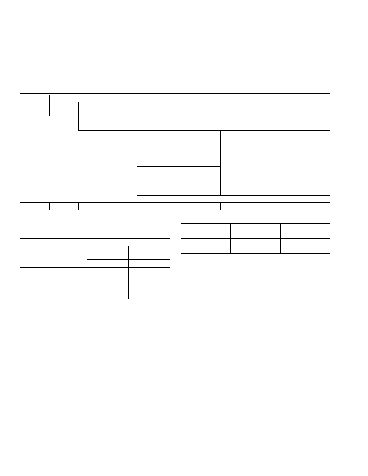
Table 1. Modutrol IV Series 2 Version Order Number Guide.
M Motor
61 Floating Control
62 Floating Control with feedback
8 60 lb-in. Spring Return 150 lb-in. Non-Spring Return
9 — 300 lb-in. Non-Spring Return
2 Dual-ended shaft Normally Closed Spring Return
4 Non-Spring Return
5 Normally Closed Spring Return
A 0 Auxiliary Switches Adjustable Stroke
B 1 Auxiliary Switch
C 2 Auxiliary Switches
D 0 Auxiliary Switch
E 1 Auxiliary Switch
F 2 Auxiliary Switches
M 61 8 4 A XXXX See Catalog for Complete O.S. Number
Electrical Ratings: See Table 2.
Table 2. Series 61 and 62 Modutrol IV Motor
Power Consumption Ratings.
Power Consumption
Non-Spring
Internal
Transformer
No 24 13 6 19 9
Yes 24 1 3 6 19 9
Auxiliary Switch Ratings: See Table 3.
Control Inputs:
Floating three-wire (Series 60): drive open, hold, drive closed.
Series 62 models include an internal, electrically isolated feed-
back potentiometer that provides shaft position
indication.
Voltage at
50/60 Hz
120 13 6 19 9
230 13 6 19 9
Return Spring Return
(VA) (W) (VA) (W)
Modutrol IV Order Number Guide: See Table 1.
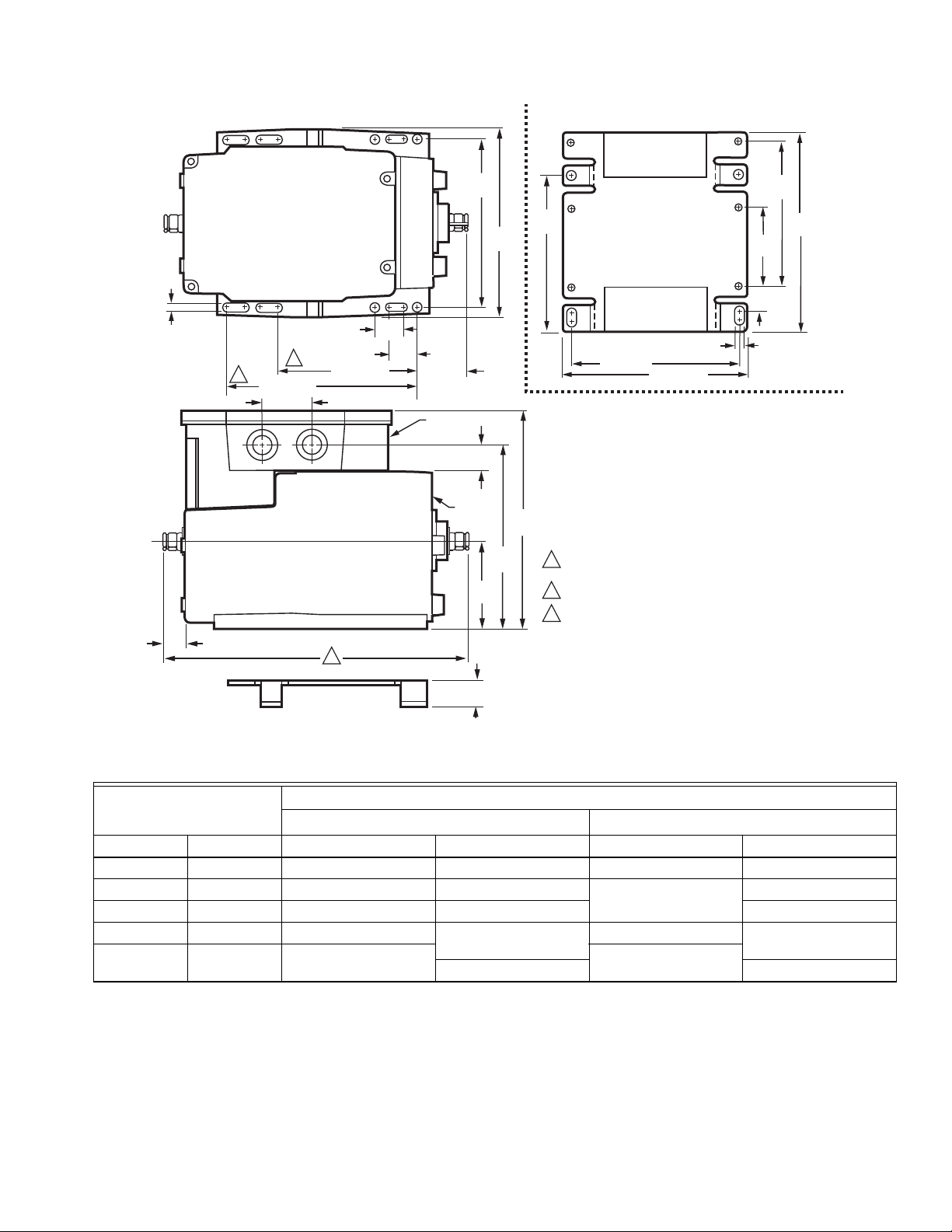
Dimensions: See Fig. 1.
Normally Closed
Table 3. Auxiliary Switch Ratings.
Single Contact
Full Load 7.2 3.6
Locked Rotor 43.2 21.6
a
40 VA pilot duty, 120/240 Vac on opposite contact.
Ambient Temperature Ratings:
Maximum: 150°F (66°C) at 25% duty cycle.
Minimum: -40°F (-40°C).
Dead Weight Load On Shaft:
Power or Auxiliary End: 200 lb (90.8 kg) maximum.
Maximum Combined Load: 300 lb (136 kg).
Crankshaft: 3/8 in. (9.5 mm) square.
Stroke: Adjustable Stroke Models: Available field-adjustable
from 90° to 160°. (See Stroke Setting procedure.)
Timing And Torque: See Table 4.
Rating
a
120V (in Amps) 240V (in Amps)
ORDERING INFORMATION
When purchasing replacement and modernization products from your TRADELINE® wholesaler or distributor, refer to the
TRADELINE® Catalog or price sheets for complete ordering number.
If you have additional questions, need further information, or would like to comment on our products or services, please write or
phone:
1. Your local Honeywell Automation and Control Products Sales Office (check white pages of your phone directory).
2. Honeywell Customer Care
1885 Douglas Drive North
Minneapolis, Minnesota 55422-4386
In Canada—Honeywell Limited/Honeywell Limitée, 35 Dynamic Drive, Scarborough, Ontario M1V 4Z9.
International Sales and Service Offices in all principal cities of the world. Manufacturing in Australia, Canada, Finland, France,
Germany, Japan, Mexico, Netherlands, Spain, Taiwan, United Kingdom, U.S.A.
63-2629—2 2
SERIES 61 AND SERIES 62 MODUTROL IV™ MOTORS
M18998B
4-7/8
(124)
5-1/2
(140)
13/16
(20)
4-1/16 (103)
1/4
(7)
1-1/2 (37)
4-1/16 (103)
JUNCTION
BOX
MOTOR
AUXILARY
END
POWER
END
ADAPTER
BRACKET
2-9/16
(66)
5-3/8
(137)
6-7/16
(164)
9/16 (15)
3/4
(19)
TOP VIEW OF BRACKET TOP VIEW
4-5/8
(116)
4-1/4
(107)
2-5/16
(58)
11/16
(17)
4-7/8 (124)
5-9/16 (141)
1/4 (7)
5-13/16
(148)
1
POWER END
2
3
1-1/2 (37)
3/4
(19)
SPRING RETURN MODEL SHOWN
FOR 60 LB-IN. SPRING RETURN MODELS 8-3/4 (222).
FOR NON-SPRING RETUIRN MODELS 7-5/16 (185).
FOR 60 LB-IN. SPRING RETURN MODELS (SHOWN).
FOR NON-SPRING RETURN MODELS.
1
2
3
13/16
(20)
Fig. 1. Series 61 and 62 Modutrol IV Motor mounting dimensions in inches (mm).
Table 4. Series 61 and 62 Modutrol IV Motor Timing and Torque Ratings.
Rated Torque in lb-in. (N•m)
Nominal Timing
90° Stroke 160° Stroke Spring Return Non-Spring Return Spring Return Non-Spring Return
15 30 — 75 (8.5) — 150 (17.0)
30 60 60 (6.8) 35 (4.0) 120 (13.6) 70 (7.9)
60 120 300 (34.0) 600 (68.0)
120 240 —
a
Timings apply to all TRADELINE models. Some OEM models are available with non-standard timing/torque.
b
Torque ratings for dual-ended shaft motors are the sum of the shaft torques (power-end torque plus auxiliary-end torque).
c
Breakaway torque is the maximum torque available to overcome occasional large loads such as a seized damper or valve.
a
in sec
Normal Running Torque Breakaway Torque
150 (17.0) 300 (34.0)
150 (17.0) 300 (34.0)
—
b
NOTE: Torque designation corresponds to torque rating at
standard timing (nominally 60 seconds for 160° and
30 seconds for 90° except for 300 lb-in. motors that
have timings of 2 or 4 minutes).
IMPORTANT
Never use motor continuously at the Breakaway
Torque rating.
Feedback Potentiometer (Series 62 Models Only):
TRADELINE Models (Can be shunted for slaving a
Series 90 Motor).
3 63-2629—2
c

SERIES 61 AND SERIES 62 MODUTROL IV™ MOTORS
CAUTION
CAUTION
CAUTION
Approvals:
Underwriters Laboratories Inc. Listed: File No. E4436, Guide
No. XAPX.
Canadian Standards Association Certified: General Listed File
No. LR1620, Guide No. 400-E.
U.S. Patents: pending
Accessories:
220736A Internal Auxiliary Switch Kit; one switch, can be field-
installed.
220736B Internal Auxiliary Switch Kit; two switches, can be
field-installed.
220738A Adapter Bracket raises motor shaft height by 3/4 inch
(19 mm) to match that of previous Modutrol Motor models.
220741A Screw Terminal Adapter converts the standard quick-
connect terminals to screw terminals.
221455A Infinitely Adjustable Crank Arm, can rotate through
downward position and clear motor base without requiring
an adapter bracket.
220738A Adapter Bracket for Modutrol IV Motor to match shaft
height of Modutrol III Motor
4074ERU Weatherproofing Kit provides NEMA 3 rating for
Modutrol IV Motors mounted in position other than upright.
50017460-001 Internal Transformer; 24/120/230 Vac 50/60 Hz
primary, 24 Vac secondary, quick connect terminals.
50017460-003 Internal Transformer; 120 Vac 50/60 Hz
primary, 24 Vac secondary, quick connect terminals.
7617ADW Crank Arm, can rotate through downward position
and clear motor base without requiring an adapter bracket.
Q100 Linkage connects Modutrol Motor to V51 Butterfly Valve.
Requires the 220738A Adapter Bracket.
Q181 Auxiliary Potentiometer for sequence or unison control of
1 to 4 additional modulating (Series 90) motors.
Q5001 Bracket and Linkage Assembly connects Modutrol IV
Motor to water or steam valve.
Q605 Damper Linkage connects motor to damper. Includes
motor crank arm.
Q607 External Auxiliary Switch controls auxiliary equipment as
a function of motor position.
ES650-117 Explosion-Proof Housing encloses motor for use in
explosive atmospheres. Not for use with Q5001 (or any
other valve linkages). Order separately from Nelson Enclosures. To order, contact: Nelson Enclosures and Controls,
(281) 449-6271; or write to:
Nelson Enclosures and Controls
P.O. Box 471650
Tulsa, OK 74147-1650
Requires Honeywell 7617DM Coupling.
INSTALLATION
When Installing this Product...
1. Read these instructions carefully. Failure to follow them
could damage the product or cause a hazardous
condition.
2. Check the ratings given in the instructions and on the
product to make sure the product is suitable for your
application.
3. Installer must be a trained, experienced service
technician.
4. After installation is complete, check out product
operation as provided in these instructions.
Electrical Shock or Equipment Damage Hazard.
Can shock individuals or short equipment
circuitry.
Disconnect all power supplies before installation.
Motors with auxiliary switches can have more than one
disconnect.
Equipment Damage Hazard.
Can damage the motor beyond repair.
Never turn the motor shaft by hand or with a wrench.
Forcibly turning the motor shaft damages the gear train
and stroke limit contacts.
IMPORTANT
Always conduct a thorough checkout when
installation is complete.
Location
Allow enough clearance for accessory installation and motor
servicing when selecting a location (see Fig. 1). If located
outdoors, use liquid-tight conduit connectors with the junction
box to provide NEMA 3 weather protection. If mounted
outdoors in a position other than upright, install a 4074ERU
Weatherproofing Kit and liquid-tight connectors to provide
NEMA 3 protection.
Motor Damage Hazard.
Deteriorating vapors and acid fumes can damage
metal parts.
Install motor in areas free of acid fumes and other
deteriorating vapors.
In excessive salt environments, mounting base and screws
should be zinc or cadmium plated, not stainless steel or brass.
Use the 220738A Adapter Bracket for mounting on these
surfaces.
Mounting
Use the following guidelines for proper motor mounting:
• Always install motors with the crankshaft horizontal.
• Mounting flanges extending from motor housing base are
drilled for 1/4 inch (6.4 mm) machine screws or bolts.
• Non-Spring Return Motors are shipped from the factory in
the closed position (at the limit of counterclockwise rotation,
as viewed from the power end of the motor).
• Spring Return Motors are shipped from the factory in their
normal position.
• Normally closed models are shipped at the limit of
counterclockwise rotation, as viewed from the power end of
the motor.
NOTE: Refer to Fig. 2 for graphical representation of
fully-open and fully-closed positions.
63-2629—2 4
 Loading...