

Page 1

Table of Contents
K595.RF Product Guide
K594.RF Product Guide
Table of Contents .............................................. Page 1
Overview and General Concept ......................... Page 2
Application ......................................................... Page 2
Features ............................................................ Page 3
Installation ......................................................... Page 3
Commissioning .................................................. Page 4
Using the E527/E527.4G ............................... Page 5
Using the E529 .............................................. Page 5
Binding the K594 ............................................... Page 6
Using the E527/E527.4G ............................... Page 6
Using the E529 .............................................. Page 7
Testing ............................................................... Page 8
PIR Specifications .............................................. Page 9
RF Specifications ............................................... Page 9
Technical Specifications .................................... Page 9
PIR Coverage .................................................... Page 11
Document Revision History................................ Page 11
Rev 2.0 3/3/2017 1
Page 2
K595.RF Product Guide
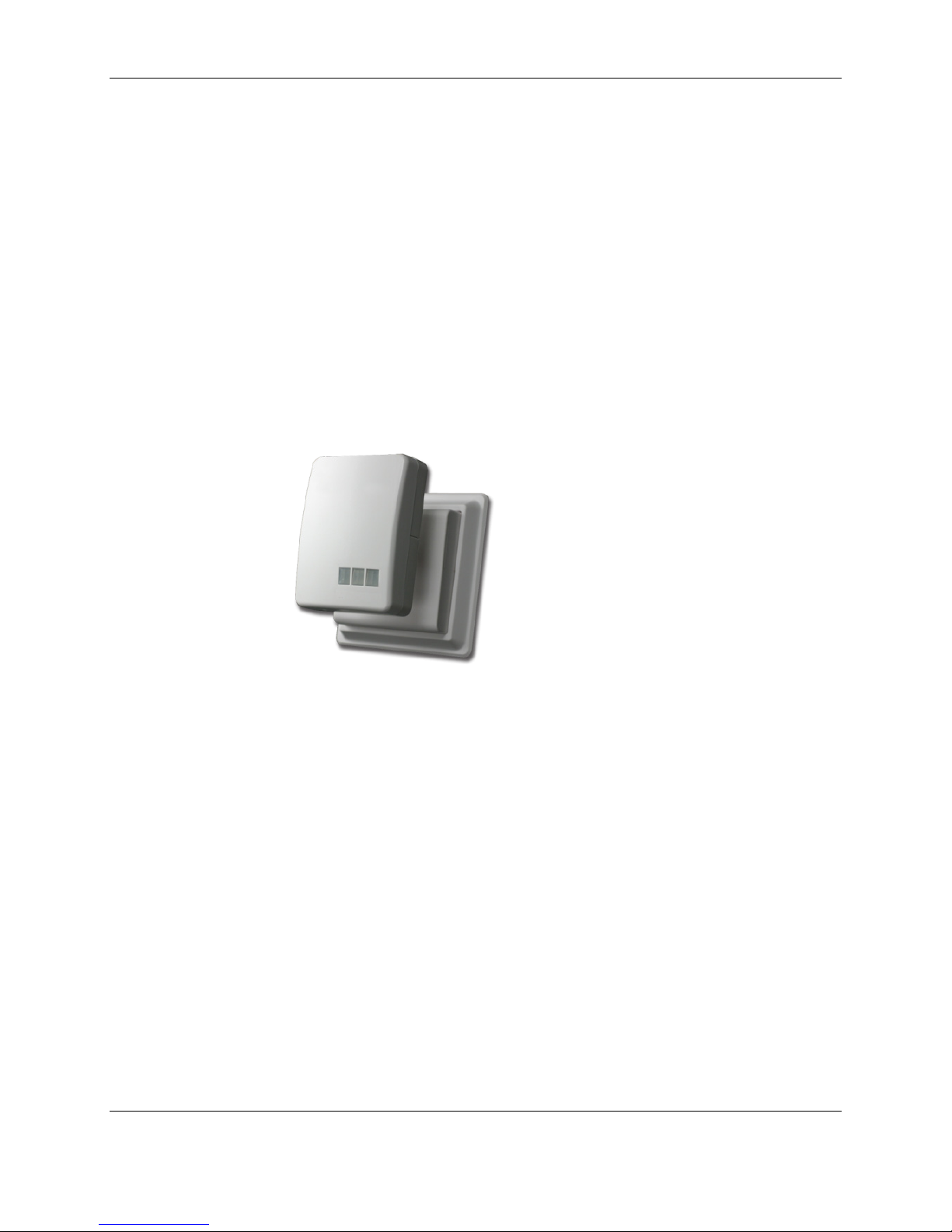
Figure 1. K594.RF Motion Sensor
Overview and
General Concepts
The K594.RF wall mounted passive infrared (PIR) motion detector (Figure 1)
adds occupancy sensing and peripheral–status reporting capability to INNCOM
integrated guestroom control systems. The K594.RF can be a key participant
in an INNCOM Integrated Room Automation System guestroom network.
The K594.RF, in conjunction with its room controller, and an in-room
communication network, helps determine guestroom occupancy. Occupancy
sensing leads to better management of energy usage and security; extends
heating, ventilation, and air conditioning equipment life; enhances the overall
operating efficiency of the hotel; and improves guest satisfaction. The
K594.RF’s swiveling head adjusts to give optimum coverage to any room
configuration.
The K594.RF can also monitor and report on the status (e.g., open/closed) of
other devices within the guestroom (see Application below).
Application
The K594.RF’s microprocessor-controlled PIR detects motion in a guestroom
and reports it to the room controller. Combined with information from other
inputs (such as a lanai or window switch or a minibar), guestroom occupancy
can be determined and used for energy control or lighting decisions.
Occupancy information may also be signaled to Housekeeping using the
corridor doorbell display or a floor-level terminal.
On power-up, the K594.RF will flash the LED for approximately two seconds as
it configures itself using settings in nonvolatile memory (see table below).
The K594.RF will then go into Operation Mode, where it checks the auxiliary
input, the motion detector, and the Bind switch status (see Commissioning).
The K594.RF will process any actions instigated by those checks; after that (or
if there is no action), it will enter a low-power state (Sleep Mode) to conserve
battery power.
The K594.RF can also act as a minibar server if the IO map is so programmed.
Rev 2.0 3/3/2017 2
Page 3

K595.RF Product Guide
Features
• Wide angle dispersion
• Swivel mounting
• Light (photo) sensor
• Auxiliary input
• Easy installation
• No maintenance
• Long battery life
• 2.4Ghz IEEE 802.15.4 compliant RF transceiver (CC2430 radio core)
• FCC Part 15b listed
Description Value
Room ID 65535
RF Channel 26
TX Power 0x5F (0dB)
P5 Address 189
P5 Channel 1
Installation
Location of the K594.RF is determined by the individual guestroom design.
Placement for the K594.RF should provide maximum room coverage by the
PIR motion detector while maintaining RF communication between the
device and the e4 thermostat. Ideally, the K594.RF should be positioned on
a wall in opposition to entrances and interior doors (8ft. high, 0° angle, 0°
pitch). It should be positioned to view both the entry door and the bed areas
of the guestroom; the swivel mounting allows adjustment for optimal
occupancy sensing.
The K594.RF should be mounted within operational range of the e4
thermostat and any other devices it may communicate with. Avoid possible
sources of radio interference such as metallic boxes, WiFi access points,
microwave ovens, water pipes, and the like.
1. Remove the mounting base from the K594.RF
2. Drill two holes in the wall corresponding to the screw holes in the base
3. Mount the base using the 6x32x1 screws supplied
4. For a wireless device, insert 4 AA batteries into the battery
compartment assembly
5. Snap the battery compartment assembly to the base
Rev 2.0 3/3/2017 3
Page 4
K595.RF Product Guide
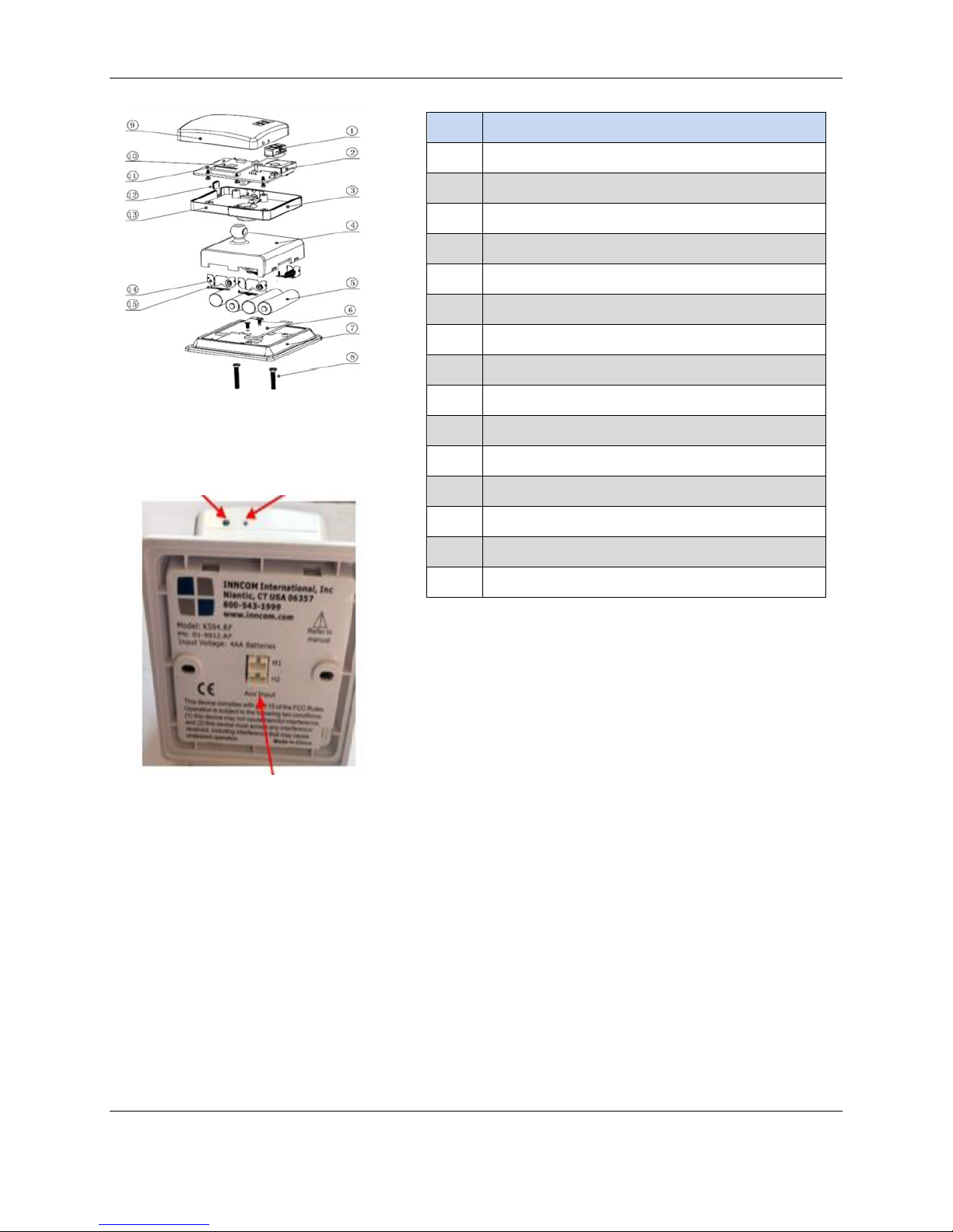
Figure 2. Mechanical Drawing
Status LED Bind Switch
H2 Aux Input Header
Item Description
1 Fresnel Lens
2 PIR Board PCBA
3 Right Side Back
4 Battery Cover
5 Battery
6 Base PCBA
7 Mounting Base
8 Screws 6x32x1
9 Front Cover
10 TXR, SMT, PCBA
11 Module PCBA
12 Photo Sensor
13 Left Side Back
14 POS/NEG Plate (R+/L-)
15 Spring Sheet
Commissioning
To function as part of the in-room network, the K594.RF must be
commissioned by accepting instruction as to room identification, RF channel,
P5 address, P5 channel, and IOMap setting for the specific room (see IOMap
Summary table below). An E528.4G, E527.4G or E529 can be used to
configure and bind the K594.RF.
Prepare the thermostat to bind the K594 by setting the Room ID, PAN ID
and RF Channel into the thermostat:
Rev 2.0 3/3/2017 4
Page 5

K595.RF Product Guide
If Using the E528/E527.4G:
1. Enter Service Parameter Mode on the Thermostat:
a) Press and hold °F/°C button
b) Press and release the OFF/AUTO button
c) Press and release the DISPLAY button
d) Release the °F/°C button rId will be on the display
2. Set the Room ID
a) Press DISPLAY button. Current Room ID will scroll, then highest Room ID digit will display
with “HI” below it. Change to desired value with UP/DOWN arrow buttons and press
OFF/AUTO button.
b) The next 2 digits of Room ID will be displayed with “MED” below it. Change to desired value with
UP/DOWN arrow buttons and press OFF/AUTO button.
c) The last 2 digits of Room ID will be displayed with “LO” below it. Change to desired value with
UP/DOWN arrow buttons and press DISPLAY button to store Room ID. The thermostat will beep
and scroll new Room ID on display.
3. Set the PAN ID
a) In Service Mode go to Pan (PAN ID) and press DISPLAY button to view value.
b) Use UP/Down arrow buttons to change to desired PAN ID.
c) Press DISPLAY to store. The thermostat will beep.
4. Set the RF Channel
a) In Service Mode go to rF (RF Channel) and press DISPLAY button to view value.
b) Use UP/Down arrow buttons to change to desired RF Channel.
c) Press DISPLAY to store. The thermostat will beep.
If Using the E529
1. Enter Service Parameter Mode on the Thermostat:
a) Press and hold °F/°C button
b) Press and release the OFF/AUTO button
c) Press and release the DISPLAY button
d) Release the °F/°C button rId will be on the display
2. Set the Room ID
a) Press OFF/AUTO button. Current Room ID will scroll, then highest Room ID digit will display with
“HI” below it. Change to desired value with UP/DOWN arrow buttons and press DISPLAY button.
Rev 2.0 3/3/2017 5
Page 6

K595.RF Product Guide
b) The next 2 digits of Room ID will be displayed with “MED” below it. Change to desired value with
UP/DOWN arrow buttons and press DISPLAY button.
c) The last 2 digits of Room ID will be displayed with “LO” below it. Change to desired value with
UP/DOWN arrow buttons and press DISPLAY button to store Room ID. The thermostat will beep
and scroll new Room ID on display.
3. Set the PAN ID
a) In Service Mode go to Pan (PAN ID) and press OFF/AUTO button to view value.
b) Use UP/Down arrow buttons to change to desired PAN ID.
c) Press DISPLAY to store. The thermostat will beep.
4. Set the RF Channel
a) In Service Mode go to rF (RF Channel) and press OFF/AUTO button to view value.
b) Use UP/Down arrow buttons to change to desired RF Channel.
c) Press DISPLAY to store. The thermostat will beep.
With the Room ID, PAN ID and RF Channel Set into the Thermostat,
Bind the K594:
If Using the E528/E527.4G:
1. In Service Parameter mode, go to the Io (I/O Map) parameter
2. Press DISPLAY button to view value.
3. Change the value to the desired I/O Map. If only using the K594 as a remote Motion Sensor and
NOT using its external input to monitor a door switch or other contact, use I/O Map 0. Otherwise,
select the appropriate I/O Map from the IOMap Summary table.
4. With the desired I/O Map selected, press the OFF/AUTO button. The display will show “bnd”.
DO NOTHING ELSE on the thermostat.
5. Press the blue S1 switch on the K595 to initiate binding. The K595 will broadcast a Bind Request
message. If the thermostat saw the Bind Request, it will reply with a Bind Offer message. Upon
seeing the Bind Offer from the E528, the K595 will bind itself to the advertised Room ID and
RF Settings.
If binding is successful, the K594 will:
• Flash its Status LED 3 times
• Send the thermostat a message to sound its buzzer
• Reset itself
• Send a device startup message that includes the K595 software version and its battery status.
Rev 2.0 3/3/2017 6
Page 7

K595.RF Product Guide
If Using the E529:
1. In Service Parameter mode, go to the Io (I/O Map) parameter
2. Press OFF/AUTO button to view value.
3. Change the value to the desired I/O Map. If only using the K594 as a remote Motion Sensor and
NOT using its external input to monitor a door switch or other contact, use I/O Map 0. Otherwise,
select the appropriate I/O Map from the IOMap Summary table. Do nothing else on the E529 at
this point.
4. Press the blue S1 switch on the K595 to initiate binding. The K595 will broadcast a Bind Request
message. If the E529 saw the Bind Request, it will reply with a Bind Offer message. Upon seeing
the Bind Offer from the E529, the K595 will bind itself to the advertised Room ID and RF Settings.
If binding is successful, the K594 will:
• Flash its Status LED 3 times
• Send the thermostat a message to sound its buzzer
• Reset itself
• Send a device startup message that includes the K595 software version and its battery status.
IO Map
Summary
IO
Map
0 Input Disabled/Not Used N/A N/A
1 Entry Door Inverted 0x028 0x029
2 Window 0x02A 0x02A
3 Window Inverted 0x02A 0x02A
4 Mini Bar 0x025 0x025
5 Mini Bar Inverted 0x025 0x025
6 Safe 0x026 0x026
7 Safe Inverted 0x026 0x026
8 Common Door 0x064 0x064
9 Common Door Inverted 0x064 0x064
10 Connecting Door 0x065 0x065
11 Connecting Door Inverted 0x065 0x065
12 Window Segment 0 0x1E 0x1E
Name VIF
Control
VIF
Reinforcement
Frame
13 Window Segment 0 Inverted 0x1E 0x1E
Rev 2.0 3/3/2017 7
Page 8

K595.RF Product Guide
IO
Map
14 Window Segment 1 0x1E 0x1E
15 Window Segment 1 Inverted 0x1E 0x1E
16 Window Segment 2 0x1E 0x1E
17 Window Segment 2 Inverted 0x1E 0x1E
18 Window Segment 3 0x1E 0x1E
19 Window Segment 3 Inverted 0x1E 0x1E
20 Window Segment 4 0x1E 0x1E
21 Window Segment 4 Inverted 0x1E 0x1E
22 Window Segment 5 0x1E 0x1E
23 Window Segment 5 Inverted 0x1E 0x1E
24 Window Segment 6 0x1E 0x1E
25 Window Segment 6 Inverted 0x1E 0x1E
26 Window Segment 7 0x1E 0x1E
Name VIF 0x1E
Control
VIF
Reinforcement
Frame
Testing
27 Window Segment 7 Inverted 0x1E 0x1E
28 Smoke 0x06B 0x06B
29 Smoke Inverted 0x06B 0x06B
30 Key Tag 0x01A 0x01A
31 Key Tag Inverted 0x01A 0x01A
To perform the PIR Walk test, press the K594 Bind switch twice quickly.
Activate the E528/E527.4G thermostat’s testing function by executing RUN
parameter 12. The E529 has no such test and can’t be used to perform the
Walk test. Motion detected by the K594 PIR should be transmitted to the
E527/E528, causing the thermostat’s buzzer to sound and “pir” to appear on
the LCD screen. The K595 will remain in PIR Walk Test mode for 60 seconds.
Rev 2.0 3/3/2017 8
Page 9

K595.RF Product Guide
0 °C to 60 °C (32 °F to 140 °F)
PIR Specification
RF Specification
Parameter K594.RF
Lens Data 70ft
No. of Fresnel Beams 27 9+5
No. of Curtain Beams MAX. Coverage 12x12m (40x40ft.) 90 degrees
Sensitivity 0.5m-12m (1.64-40ft)
Parameter K594.RF
RF Data Rate 250kbps
Antenna Type SMT
Indoor Range 70ft
Transmit Power 1mW (+0dBm)
Receive Sensitivity -94.6dBm
Frequency Band 2.4 Ghz
Encryption AES-128
Protocol 802.15.4
Frequency Channels 11-26
Technical Specifications
Parameter K594.RF
Input Voltage 4 x AA Batteries
Battery Life 2.2 Years
Operating Temperature
Storage Temperature -20 °C to 60 °C (-4 °F to 140 °F)
Rev 2.0 3/3/2017 9
Page 10

K595.RF Product Guide
Safety Regulatory
FCC ID: GTC202150TXR or GTC202152TXR
This equipment has been tested and found to comply with the limits for a Class
B digital device, pursuant to Part 15 of the FCC Rules. These limits are
designed to provide reasonable protection against harmful interference in a
residential installation. This equipment generates, uses, and can radiate radio
frequency energy and, if not installed and used in accordance with the
instructions, may cause harmful interference to radio communications.
However, there is no guarantee that interference will not occur in a particular
installation. If this equipment does cause harmful interference to radio or
television reception, which can be determined by turning the equipment off and
on, the user is encouraged to try to correct the interference by one of the
following measures:
• Reorient or relocate the receiving antenna.
• Increase the separation between the equipment and receiver.
• Connect the equipment into an outlet on a circuit different from
that to which the receiver is connected.
• Consult the dealer or an experienced radio/TV technician
for help.
Any changes or modifications not expressly approved by the party responsible
for compliance could void the user's authority to operate this equipment.
IC ID: 1609A-202150TXR, or 1609A-202152TXR
This device complies with Industry Canada license-exempt RSS standard(s).
Operation is subject to the following two conditions: (1) this device may not
cause interference, and (2) this device must accept any interference, including
interference that may cause undesired operation of the device.
Le présent appareil est conforme aux CNR d’industrie Canada applicables aux
appareils radio exempts de licence. L’exploitation est autorisée aux deux
conditions suivantes: (1) l’appareil ne doit pas produire de brouillage, et (2)
l’utilisateur de l’appareil doit accepter tout brouillage radioélectrique subi,
même si le brouillage est susceptible d’en compromettre le fonctionnement.
Rev 2.0 3/3/2017 10
Page 11
K595.RF Product Guide
REVISION
DATE ISSUED
REASON FOR CHANGE
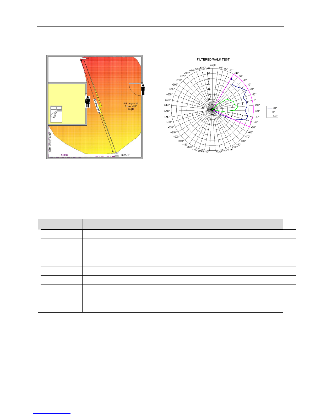
This chart graphs the testing of the
PIR Coverage
effective range of the K594.RF’s PIR
motion detector through 180° of horizontal
movement (-90° to +90°) and 40° of
vertical movement (-20° to +20°).
Document Revision History
0.1 18-NOV-2009 First Draft
0.2 03-DEC-2009 Incorporate Comments from Technical Review
0.3 08-DEC-2009 Final Revisions Before Review
1.0 08-DEC-2009 Release to Grid
1.1 18-FEB-2010 Updated FCC Statement
1.2 09-MAT-2012 Changed Battery Life
1.3 15-JUL-2013 Changed OPN
1.4 25-JUL-2014 Changed Binding Procedure to Reflect Reverse Binding
2.0 03-MAR-2017 Rebranded to Honeywell Design Specifications
The material in this document is for information purposes only. The content and the product it describes are subject to
change without notice. Honeywell makes no representations or warranties with respect to this document. In no event shall
Honeywell be liable for technical or editorial omissions or mistakes in this document, nor shall it be liable for any damages,
direct or incidental, arising out of or related to the use of this document. No part of this document may be reproduced in
Honeywell I 277 West Main Street I Niantic, CT 06357 I Phone: 1.860-739-4468 I www.INNCOM.com
any form or by any means without prior written permission from Honeywell.
Copyright © 2017 by Honeywell International, Inc. All Rights Reserved.
Rev 2.0 3/3/2017 11
 Loading...