

Page 1
OWNER'S MANUAL
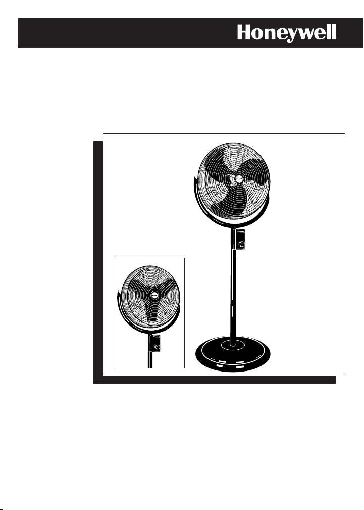
14"/18" (35CM/45CM) COMMERCIAL GRADE
STAND FAN
Model HV-141 without base weight
HV-181 with base weight
HV-181
E
HV-141
R
M
C
I
M
A
O
L
C
G
E
R
D
A
C
O
M
M
E
R
C
I
A
L
G
R
A
H
I
G
H
M
E
D
O
F
F
L
O
W
E
R
C
M
I
M
A
O
L
C
G
E
R
D
A
C
O
M
M
E
R
C
IA
L
G
R
A
D
E
H
I
G
H
M
E
D
O
F
F
L
O
W
D
E
Page 2

READ AND SAVE THESE
IMPORTANT SAFETY
INSTRUCTIONS BEFORE
USING THIS FAN.
When using electrical
appliances, basic safety
precautions should
always be followed,
including the following:
• Use this fan only as
described in this manual.
Other use not
recommended may
cause fire, electric shock
or injury.
• High Velocity fans are
designed to create rapid
air movement; therefore,
make sure the fan is not
placed near drapes,
curtains, or any objects
that may be drawn into
the fan.
• To protect against
electrical shock, do not
immerse unit, plug or
cord in water or spray
with liquids.
• This fan requires a
grounded 120 volt
power source (3 prong
receptacles).
NEVER CONNECT THIS
FAN TO ANY POWER
SOURCE OTHER THAN
A PROPERLY GROUNDED
120 VOLT AC
RECEPTACLE. DO NOT
ATTEMPT TO DEFEAT
THIS SAFETY FEATURE.
• Close supervision is
necessary when any
appliance is used by
or near children.
• Turn the fan to the OFF
position and unplug the
fan from the outlet when
not in use, when moving
fan from one location to
another, servicing parts
and before cleaning.
• Do not operate fan in
the presence of explosive
and/or flammable fumes.
• Do not place the fan or
any parts near an open
flame, cooking or other
heating appliance.
• Do not operate the fan
with a damaged cord or
plug, after a malfunction
or if dropped or damaged
in any manner. (See
warranty)
• Avoid contact with
moving fan parts.
• To disconnect, grip the
plug and pull it from the
wall outlet. Never pull
by the cord.
• The use of attachments
not recommended by
Honeywell Consumer
Products may be
hazardous.
SAFETY INSTRUCTIONS
• Always use on a dry,
level surface.
• Do not hang or mount
fan on a wall or ceiling.
• Do not operate without
the fan grilles properly
in place.
• Be sure to center this
fan when using it on an
elevated surface and be
careful not to place the
fan too close to the edge
of that surface.
• Do not use outdoors.
• Do not let the power
cord hang over the edge
of a table or counter or
let it touch any hot
surfaces.
• A loose fit between the
AC outlet and plug may
cause overheating of the
plug. Have a qualified
electrician replace
the outlet.
WARNING: To reduce the
risk of fire or electrical
shock, DO NOT USE THIS
FAN with any SOLID
STATE Speed Control
Device.
Page 3
BASE ASSEMBLY INSTRUCTIONS
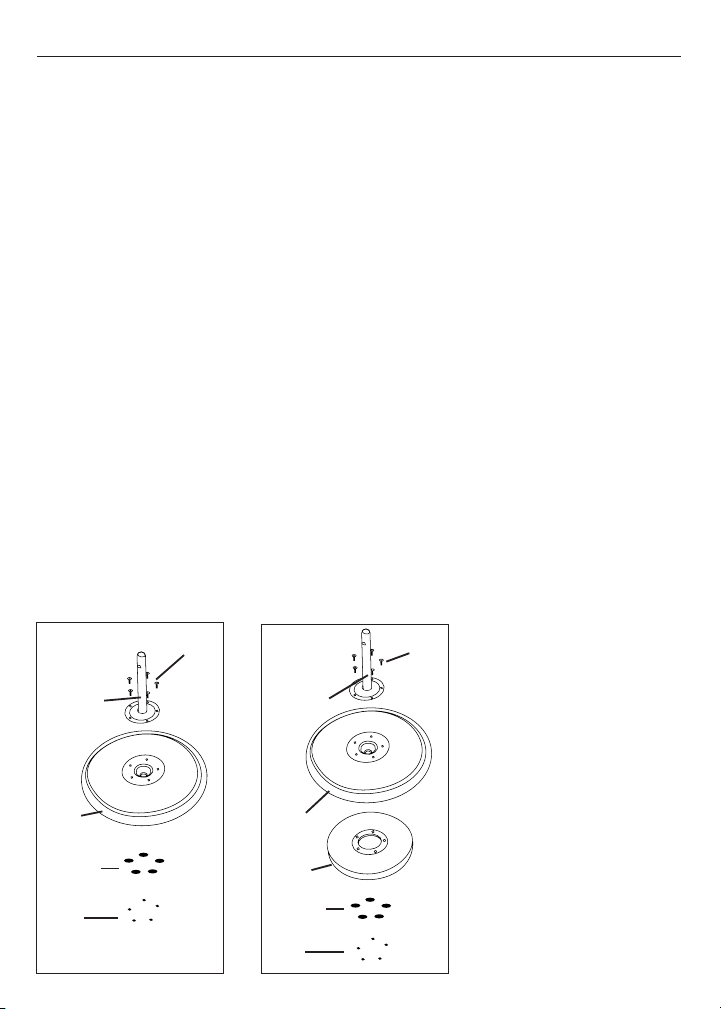
NOTE: THESE
INSTRUCTIONS ARE FOR
MODEL HV-141 (NO BASE
WEIGHT INCLUDED/FIG. 1)
AND HV-181 (WITH BASE
WEIGHT/FIG. 1A).
IF YOU HAVE MODEL HV141 (Fig.1), PLEASE FOLLOW
THESE INSTRUCTIONS BUT
DISREGARD REFERENCES
TO BASE WEIGHT.
• Remove the base extension
pole, base with attached
base weight (Fig.1A), #10
metric socket wrench and
(5) bolts and (5) nuts from
the box.
• Place the base on the
floor with the weight on
the bottom, line up the base
extension pole holes with
those in the base and firmly
insert the pole into the base.
NOTE: It may be
easier for you to
insert and tighten
each bolt individually
instead of all 5 at
once. Use the method
you are most
comfortable with.
• When you are finished
attaching all (5) bolts, flip
the base back over so
that the base extension
pole is now facing up.
• Separate the nut and metal
washer from each bolt.
• Using your fingers, press
one bolt through the base
extension pole plate, and
into the base until it is
almost flush with the plate.
• Once the bolt is inserted,
carefully turn over the base
and pole so the base weight
is facing upright.
• Take a metal washer and
drop it into the hole so it fits
around the bolt.
• Then take a nut and fit it
into the #10 metric socket
wrench (included). You may
then, using the tool, thread
and secure the nut around
the bolt. Do not completely
tighten
• Repeat for all 5 bolts,
then tighten.
Fig. 1
BASE
EXTENSION
POLE
BASE
BOLTS
NUTS
Fig. 1A
BASE
EXTENSION
POLE
BASE
BOLTS
BASE
WEIGHT
NUTS
WASHERS
WASHERS
HV-181
HV-141
Page 4
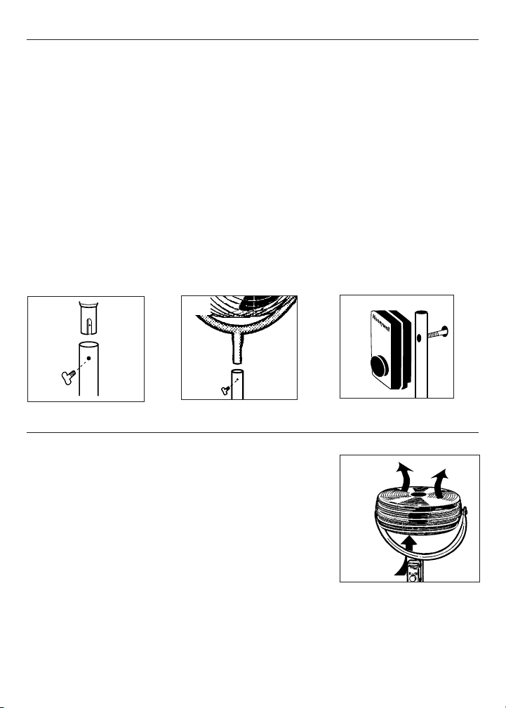
• Place the metal stand
fan pole into the base
extension, lining up the
groove of the pole to the
hole in the base
extension.
• Push together until the
holes (in the groove) line
up (Fig. 2).
•
Insert and hand tighten
the locking thumb screw.
➡
➡
Fig. 2
➡
➡
Fig. 3
• Unscrew the control box
locking knob from the
control box.
• Push the control box
extension through the hole
in the fan pole (Fig. 4). Be
sure that the power cord
from the control box to the
fan is always free hanging.
• From the rear, tighten the
control box holding knob.
DO NOT OVERTIGHTEN.
ASSEMBLY INSTRUCTIONS
• Place the fan assembly
over the metal stand pole
while lining up the groove
from the fan assembly
with the hole in the fan
pole. Push together and
line up the holes (Fig. 3).
• Insert the fan locking
thumb screw and hand
tighten.
➡
Commercial
Grade
Fig. 4
OPERATION
• Set your fan on a level,
dry surface.
• Plug the power cord
into a grounded three
prong wall outlet.
• Select the desired
speed for your needs
• Tilt the fan assembly to
the desired air direction.
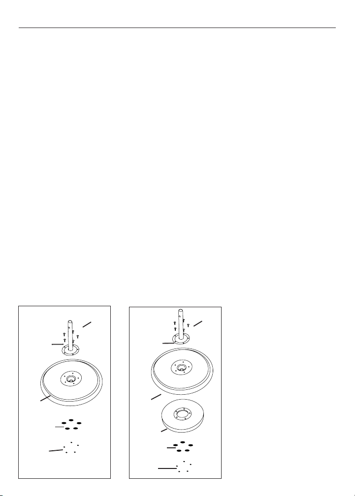
• For maximum
circulation, you may
point the fan toward the
ceiling and get the
maximum air turbulence
(Fig. 5). Using this
method in the summer
will circulate air
providing a “wind chill”
effect, and in the winter
will move the warm air
from the ceiling,
dispersing it and giving
you a more uniform room
temperature.
Fig. 5
Page 5

• Turn the Control to OFF
and UNPLUG THE FAN
BEFORE CLEANING.
• NOTE: fan housing does
not disassemble.
• Use only a soft, damp
cloth to clean the fan.
• DO NOT immerse the fan
in water and never allow
water to drip into the
Motor Housing.
• DO NOT use gasoline, paint
thinner or other chemicals
to clean the fan.
• Store the fan in its original
box or cover the fan to
protect it from dust.
CLEANING AND STORAGE
Fig. 6
NOTE: Your fan motor
does not need to be oiled.
It is permanently sealed
and lubricated.
CONSUMER RELATIONS/REPLACEMENT PARTS
To order by mail, please include $4.50 U.S./$6.00 CAN. for shipping and handling and make
check or money order payable to Honeywell Consumer Products Business. For Canadian
residents
please add 7% GST plus applicable provincial sales tax. Mail to:
Consumer Relations
Honeywell Consumer Products Business
250 Turnpike Road
Southborough, MA 01772 USA
Note: Honeywell Consumer Products Business can not ship to
P.O. Box numbers
Thank you for purchasing a Honeywell fan. To learn more about Honeywell please
visit us at www
.honeywell.com
To speak with a technical representative or place an order, please call our Consumer Relations
Center, toll-free, at : 1-800-332-1110. Orders may be placed with Master Card, Visa or Discover.
HV-141 HV-181
ITEM PART NO. PART NO. PRICE U.S PRICE CAN.
Fan Control Holding Knob HV-141-2 HV-181-2 $ 4.00 $ 5.40
Round Base HV-141-4 HV-181-4 $ 15.00 $ 20.25
Base Extension HV-141-5 HV-181-5 $ 10.00 $ 13.50
Fan Pole HV-141-6 HV-181-6 $ 10.00 $ 13.50
Locking Thumb Screws (set of 2) HV-141-7 HV-181-7 $ 4.00 $ 5.40
Base Locking Screws (set of 2) HV-141-8 HV-181-8 $ 4.00 $ 5.40
#10 Metric Socket Wrench HV-141-9 HV-181-9 $ 4.00 $ 5.40
Page 6

5 YEAR LIMITED WARRANTY
©1999 All rights reserved. Honeywell Consumer Products
P/N 035-00010-001 Rev. 1 F1004.99
Artwork # 043-50101-000
You should first read all
instructions before
attempting to use this
product.
The enclosed Customer
Response card should
be filled out and returned
within 7 days of
purchase.
A
. This 5 year limited
warranty applies to
repair or replacement of
product found to be
defective in material or
workmanship. This
warranty does not apply
to damage resulting from
commercial, abusive,
unreasonable use or
supplemental damage.
Defects that are the
result of normal wear
and tear will not be
considered
manufacturing defects
under this warranty.
HONEYWELL IS NOT
LIABLE FOR INCIDENTAL
OR CONSEQUENTIAL
DAMAGES OF ANY
NATURE. ANY IMPLIED
WARRANTY OF
MERCHANTABILITY OR
FITNESS FOR A
PARTICULAR PURPOSE
ON THIS PRODUCT IS
LIMITED IN DURATION
TO THE DURATION OF
THIS WARRANTY
.
Some jurisdictions do not
allow the exclusion or
limitation of incidental or
consequential damages
or limitations on how
long an implied warranty
lasts, so the above
limitations or exclusions
may not apply to you.
This warranty gives you
specific legal rights, and
you also may have other
rights which vary from
jurisdiction to
jurisdiction. This
warranty applies only to
the original purchaser
of this product from the
original date of purchase.
B. At its option, Honeywell
will repair or replace this
product if it is found to be
defective in material or
workmanship. Defective
product should be
returned to the place of
purchase in accordance
with store policy.
Thereafter, while within
the warranty period
defective product may be
returned to Honeywell.
C. This warranty does not
cover damage resulting
from any unauthorized
attempts to repair or from
any use not in
accordance with the
instruction manual.
D. Return defective
product to Honeywell
Consumer Products with
a brief description of the
problem. Include proof of
purchase and a $15.00
US/$ 19.85 CAN check or
money order for handling,
return packing and
shipping charges. Please
include your name,
address and a daytime
phone number.
You must prepay shipping
charges. Send to:
Honeywell
Attn: Returns Department
4755 Southpoint Drive
Memphis, TN 38118
USA.
5 YEAR LIMITED WARRANTY
Page 7

GUIDE D’UTILISATION
VENTILATEUR SUR PIED 14 PO/18 PO
(35 CM/45 CM) DE CALIBRE COMMERCIAL
Modèle HV-141 sans poids pour la base
HV-181 avec poids pour la base
HV-181
HV-141
E
R
C
M
I
M
A
O
L
C
G
E
R
D
A
C
O
M
M
E
R
C
IA
L
G
R
A
D
E
H
I
G
H
M
E
D
O
F
F
L
O
W
E
R
C
M
I
M
A
O
L
C
G
E
R
D
A
C
O
M
M
E
R
C
I
A
L
G
R
A
D
E
H
I
G
H
M
E
D
O
F
F
L
O
W
Page 8

LIRE CES IMPORTANTES
INSTRUCTIONS AVANT
D’UTILISER LE VENTILATEUR.
CONSERVER CES
INSTRUCTIONS POUR LES
CONSULTER AU BESOIN.
L'utilisation d'appareils
électriques nécessite des
précautions élémentares,
incluant celles qui figurent
ci-dessous :
• Utiliser uniquement ce
ventilateur conformément aux
directives contenues dans le
présent guide d'utilisation.
Tout autre usage non
recommandé par le fabricant
pourrait être cause
d'incendie, de choc électrique
ou de blessures.
• Les ventilateurs haute
vélocité sont conçus pour
créer une circulation d’air
rapide. Il faut donc éviter de
placer le ventilateur à
proximité de tentures, de
rideaux ou de tout autre objet
qui pourrait être attiré dans
l’orifice d’admission d’air
du ventilateur.
• Afin de prévenir les chocs
électriques, éviter de placer
le ventilateur dans une
fenêtre, d’immerger l’appareil,
son cordon d’alimentation
ou sa fiche dans l’eau ou
de vaporiser du liquide
ur l’appareil.
• Ce ventilateur doit être
branché dans une prise de
courant mise à la terre de 120
volts (prise à trois alvéoles).
NE JAMAIS BRANCHER LE
VENTILATEUR DANS UNE
PRISE DE COURANT AUTRE
QU’UNE PRISE MISE À LA
TERRE DE 120 VOLTS,
COURANT ALTERNATIF.
ÉVITER DE CONTOURNER CE
DISPOSITIF DE SÉCURITÉ.
• Une étroite surveillance est
recommandée au moment
d'utiliser tout appareil en
présence d'enfants.
• Régler le ventilateur à la
position OFF et le débrancher
quand il ne sert pas ou avant
de le déplacer ou d’en
effectuer l’entretien ou le
nettoyage.
• Éviter de faire fonctionner
l'appareil en présence de
vapeurs explosives ou
inflammables.
• Éviter de placer le ventilateur
ou des pièces du ventilateur à
proximité d’une flamme ou
d’un appareil de cuisson ou
de chauffage.
• Éviter d'utiliser le ventilateur
si la fiche ou le cordon
d'alimentation est
endommagé. Éviter également
d'utiliser l'appareil si celui-ci a
montré des signes de mauvais
fonctionnement, si on l'a laissé
tomber ou s'il a été
endommagé de quelque façon
que ce soit.
(Consulter la garantie.)
• Éviter tout contact avec des
pièces mobiles du ventilateur.
• Pour débrancher le
ventilateur, tenir la fiche et
tirer pour la sortir de la prise
de courant. Ne jamais
débrancher l’appareil en tirant
sur le cordon d’alimentation.
• L’utilisation d’accessoires
non recommandés par
Honeywell Consumer Products
peut entraîner un danger.
INSTRUCTIONS DE SÉCURITÉ
• Toujours placer l’appareil
sur une surface sèche et bien
horizontale.
• Éviter de suspendre ou fixer
le ventilateur au mur ou au
plafond.
• Éviter de faire fonctionner le
ventilateur si ses grilles ne
sont pas bien fixées en place.
• S’assurer de bien centrer ce
ventilateur si on l’utilise sur
une surface élevée. Éviter de
placer le ventilateur trop près
du bord d’une surface élevée.
• Éviter d’utiliser le ventilateur
en plein air.
• Éviter de laisser pendre le
cordon d’alimentation d’un
dessus de table ou d’un
comptoir ou de le mettre en
contact avec une surface
chaude, quelle qu’elle soit.
• Une mauvaise connexion
entre la sortie de courant
alternatif et la fiche peut
provoquer un échauffement
excessif de la fiche.
Demander à un électricien
qualifié de remplacer la prise
de courant.
MISE EN GARDE : Afin de
réduire le risque d’incendie
ou de choc électrique, É´viter
d’utiliser une commande de
vitesse transistorisée avec
le ventilateur.
Page 9
INSTRUCTIONS D’ASSEMBLAGE DE LA BASE
REMARQUE : CES
INSTRUCTIONS
S’APPLIQUENT AUX
MODÈLES HV-141 (SANS
POIDS POUR LA BASE/FIG. 1)
ET HV-181 (AVEC POIDS
POUR LA BASE/FIG. 1A).
POUR LE MODÈLE HV-14
(FIG. 1), SUIVRE CES
INSTRUCTIONS EN NE TENANT
PAS COMPTE DES RÉFÉRENCES
AU POIDS DE LA BASE..
• Retirer de la boîte le poteau de
rallonge de la base, la base et le
poids qui s’y rattache (Fig. 1A), le
tournevis à douille no 10, (5)
boulons et (5) écrous.
• Placer la base sur le sol, en
plaçant le poids en dessous.
Aligner les trous pratiqués dans
le poteau de rallonge de la base
avec les trous pratiqués dans la
base et insérer fermement le
poteau dans la base.
REMARQUE : Il pourrait
être plus facile d’insérer
et de serrer chaque
boulon tour à tour plutôt
que les cinq à la fois.
Chaque personne peut
adopter la méthode qui lui
convient le mieux.
• Une fois les (5) boulons
en place, remettre la base
à l’endroit, de façon que le
poteau de rallonge de la
base soit dirigé vers le
haut.
• Séparer l’écrou et la rondelle
métallique de chacun des
boulons.
• Avec les doigts, insérer chaque
boulon à travers la plaque du
poteau de rallonge de la base et
dans la base elle-même jusqu’à
ce que le boulon soit presque au
même niveau que la plaque.
• Une fois le boulon inséré,
renverser avec précaution la
base et le poteau de sorte que
le poids de la base soit dirigé
vers le haut.
• Prendre une rondelle de métal
et la laisser tomber dans le trou
de façon qu’elle entoure le
boulon.
• Prendre ensuite un écrou et
l’insérer dans le tournevis à
douille no 10 (fourni). À l’aide de
l’outil, visser l’écrou autour du
boulon. Ne pas serrer
complètement.
• Répéter ces opérations pour les
5 boulons, puis serrer les boulons.
Fig. 1
POTEAU DE
RALLONGE
DE LA BASE
BASE
BOULONS
ÉCROUS
Fig. 1A
POTEAU DE
RALLONGE
DE LA BASE
BASE
BOULONS
POIDS DE
LA BASE
ÉCROUS
RONDELLES
RONDELLES
HV-181
HV-141
Page 10

• Placer le poteau métallique
du ventilateur sur pied dans la
rallonge de la base en
alignant la rainure du poteau
avec le trou de la rallonge de
la base.
• Pousser jusqu’à ce que les
trous (dans la rainure) soient
alignés (Fig. 2).
• Insérer et serrer à la main la
vis de blocage à oreilles.
➡
➡
Fig. 2
➡
➡
Fig. 3
• Dévisser le bouton de
verrouillage de la boîte
de commande.
• Pousser la rallonge de la
boîte de commande dans le
trou du poteau du ventilateur
(Fig. 4). S’assurer de laisser
pendre librement le cordon
d’alimentation reliant la boîte
de commande au ventilateur.
• À l’arrière, serrer le
bouton de fixation de la
boîte de commande. ÉVITER
DE TROP SERRER.
INSTRUCTIONS D’ASSEMBLAGE
• Placer le module du
ventilateur au-dessus du
poteau métallique en alignant
la rainure du module du
ventilateur avec le trou du
poteau. Pousser les deux
éléments l’un contre l’autre et
aligner les trous (Fig. 3).
• Insérer et serrer à la main la
vis de blocage à oreilles.
➡
Commercial
Grade
Fig. 4
FONCTIONNEMENT
• Placer le ventilateur sur
une surface sèche et bien
horizontale.
• Brancher le cordon
d’alimentation dans une prise
de courant triphasée (mise à
la terre).
• Choisir la vitesse désirée
selon ses besoins.
• Régler la position du
ventilateur de façon à diriger
le jet d’air à l’endroit désiré.
• Pour une circulation d’air
maximale, on peut orienter le
ventilateur vers le plafond
(Fig. 5). L’utilisation de cette
méthode l’été permet de créer
un «facteur vent», tandis
qu’elle permet, l’hiver, de
déplacer l’air chaud qui se
trouve au plafond, de le
disperser et d’obtenir ainsi
une température plus
uniforme dans une pièce.
Fig. 5
Page 11

• Régler la commande à la
position OFF et DÉBRANCHER
LE VENTILATEUR AVANT DE
LE NETTOYER.
• REMARQUE : Le boîtier du
ventilateur ne peut être
démonté.
• Nettoyer le ventilateur au
moyen d’un linge doux humide
uniquement.
• ÉVITER de plonger le
ventilateur dans l’eau ou de
laisser de l’eau s’infiltrer dans
le boîtier du moteur.
• ÉVITER d’utiliser de
l’essence, du diluant pour
peintures ou un autre produit
chimique pour nettoyer le
ventilateur.
• Ranger le ventilateur dans
sa boîte d’origine ou le couvrir
pour le protéger de la
poussière.
NETTOYAGE ET ENTREPOSAGE
REMARQUE : Le moteur du
ventilateur n’a pas besoin
d’être lubrifié. Il est scellé
et lubrifié en permanence.
SERVICE À LA CLIENTÈLE/
PIÈCES DE RECHANGE DISPONIBLES
Pour commander des pièces de rechange, faire le chèque ou le mandat de poste
à l’ordre de Honeywell Consumer Products Business, en incluant la somme de
4,50 $ US/6,00 $ CAN. pour les frais d’expédition et de manutention. Prière d’ajouter la TPS et les
taxes provinciales applicables. Poster le tout à :
Consumer Relations
Honeywell Consumer Products Business
250 Turnpike Road
Southborough, MA 01772 USA
Remarque : Honeywell Consumer Products Business ne peut expédier des marchandises à un
numéro de boîte postale.
Merci d’avoir acheté un ventilateur Honeywell. Pour en savoir plus sur Honeywell, visitez notre site
Web à www
.honeywell.com
Pour parler à un représentant du service technique ou pour donner une commande, prière de
communiquer avec notre Centre du Service à la clientèle, en composant sans frais le 1-800-332-1110. On
peut commander 24 heures par jour, sept jours sur sept, en réglant avec Master Card, Visa ou Discover.
HV-141 HV-181
ARTICLE N° DE PIÈCE N° DE PIÈCE PRIX U.S. PRIX CAN.
Bouton de fixation de la boîte
de commande HV-141-2 HV-181-2 4,00 $ 5,40 $
Base ronde HV-141-4 HV-181-4 15,00 $ 20,25 $
Rallonge de la base HV-141-5 HV-181-5 10,00 $ 13,50 $
Poteau du ventilateur HV-141-6 HV-181-6 10,00 $ 13,50 $
Vis de blocage à oreilles (jeu de 2) HV-141-7 HV-181-7 4,00 $ 5,40 $
Vis de blocage de la base (jeu de 2) HV-141-8 HV-181-8 4,00 $ 5,40 $
Clé à douille no10 HV-141-9 HV-181-9 4,00 $ 5,40 $
Page 12

GARANTIE LIMITÉE DE 5 ANS
©1999 Tous droits réservés. Honeywell Consumer Products
P/N 035-00010-001 Rév. 1 F1004.99
Illustration no 043-50101-000
Prière de lire toutes les
instructions avant de tenter
d'utiliser ce produit.
La carte ci-jointe doit être
remplie et retournée dans les
7 jours suivant l'achat.
A. Cette garantie limitée de 5
ans s'applique à la réparation
ou au remplacement d'un
produit comportant un vice de
matière ou de main-d'oeuvre.
Cette garantie ne s'applique
pas aux dégâts découlant
d'un usage abusif ou
déraisonnable, ni aux dégâts
supplémentaires. Les
défaillances résultant de
l’usure normale ne sont pas
considérées comme des vices
de fabrication en vertu de la
présente garantie.
HONEYWELL N'EST
NULLEMENT RESPONSABLE
DES DOMMAGES FORTUITS
OU INDIRECTS, QUELS QU'ILS
SOIENT. TOUTE GARANTIE
IMPLICITE DE QUALITÉ
MARCHANDE ET DE
CONVENANCE RELATIVE À CE
PRODUIT A LA MÊME DURÉE
LIMITE QUE LA PRÉSENTE
GARANTIE. Dans certaines
régions, on ne permet pas
l’exclusion ou la limitation des
dommages fortuits ou
indirects, ni les limites de
durée applicables à une
garantie implicite; par
conséquent, il est possible
que ces limitations ou
exclusions ne s’appliquent
pas dans votre cas. Cette
garantie vous confère des
droits précis, reconnus par la
loi. Ces droits diffèrent d’une
région à l’autre, et il est
possible que vous en ayez
d’autres. Cette garantie
s'applique uniquement à
l'acheteur initial de ce
produit, à compter de la date
de l’achat.
B. À sa discrétion, Honeywell
réparera ou remplacera ce
produit si l'on constate qu'il
comporte un vice de matière
ou de main-d'oeuvre. Tout
produit défectueux devrait
être retourné à l’endroit où il a
été acheté, conformément à
la politique du magasin. Par la
suite, tout produit défectueux
dont la garantie est toujours
valide peut être retourné à
Honeywell.
C. Cette garantie ne couvre
pas les dommages découlant
des tentatives de réparation
non autorisées ou de toute
utilisation non conforme au
guide d’utilisation.
D. Retourner tout produit
défectueux à Honeywell
Consumer Products,
accompagné d'une brève
description du problème.
Inclure une preuve d'achat et
un chèque ou mandat-poste
de 15,00 $ US/19,85 $ can.
pour les frais de manutention,
d'emballage de retour et
d'expédition. Prière d’indiquer
nom, adresse et numéro de
téléphone durant la journée.
Les frais d'expédition doivent
être payés à l'avance.
Adresser à :
Honeywell
Attn: Returns Department
Southpoint Distribution
Center4755 South Point
DriveMemphis, TN 38118
USA
 Loading...