

Page 1

High-Performance
Process Manager
Planning
HP02-500
Page 2

Page 3

System Site Planning - 2
High-Performance
Process Manager
Planning
HP02-500
Release 530
CE Compliant
3/98
Page 4

Copyright, Notices, and Trademarks
© Copyright 1995 - 1998 by Honeywell Inc.
Revision 05 – March 20, 1998
While this information is presented in good faith and believed to be accurate,
Honeywell disclaims the implied warranties of merchantability and fitness for a
particular purpose and makes no express warranties except as may be stated in its
written agreement with and for its customer.
In no event is Honeywell liable to anyone for any indirect, special or consequential
damages. The information and specifications in this document are subject to
change without notice.
TotalPlant, TDC 3000, Process Manager, and SMARTLINE are U.S. registered
trademarks of Honeywell Inc.
Honeywell
Industrial Automation and Control
Automation College
2820 West Kelton Lane
Phoenix, AZ 85023
1-800-852-3211
ii HPM Planning 3/98
Page 5

About This Publication
This manual provides information necessary to properly plan the installation of a High-Performance
Process Manager (HPM) subsystem at a TPS system site. The subsystem encompasses the HighPerformance Process Manager and the Network Interface Module (NIM), which is resident on the
Universal Control Network (UCN), a network associated with the TPS system Local Control
Network (LCN). The amount of information that this publication provides depends on your
personal experience and the process that the High-Performance Process Manager will control and
monitor.
The experienced planner, a person involved in the installation of TPS system’s Basic or LCN
equipment, will find that some information is familiar. However, regardless of your past
experience, you must read Section 4 in this manual to enhance your knowledge of the process
control connections available, and also reference the TPS System Site Planning, Universal Control
Network Planning, and Universal Control Network Installation manuals to prepare yourself for the
connection of the High-Performance Process Manager to the Universal Control Network.
In some cases, control room expansion will be part of installing the High-Performance Process
Manager. If this is the case, use the LCN Planning and LCN Installation manuals to plan for
expansion of the network.
This publication supports TotalPlant Solution (TPS) system network software Release 530 or earlier
software releases. TPS is the evolution of TDC 3000X.
The publication supports CE Compliant equipment. Any equipment designated as “CE Compliant”
complies with the European Union EMC and its health and safety directives. All equipment entering
the European countries after January 1, 1996 require this type of compliance, denoted by the
“CE Mark.”
3/98 HPM Planning iii
Page 6
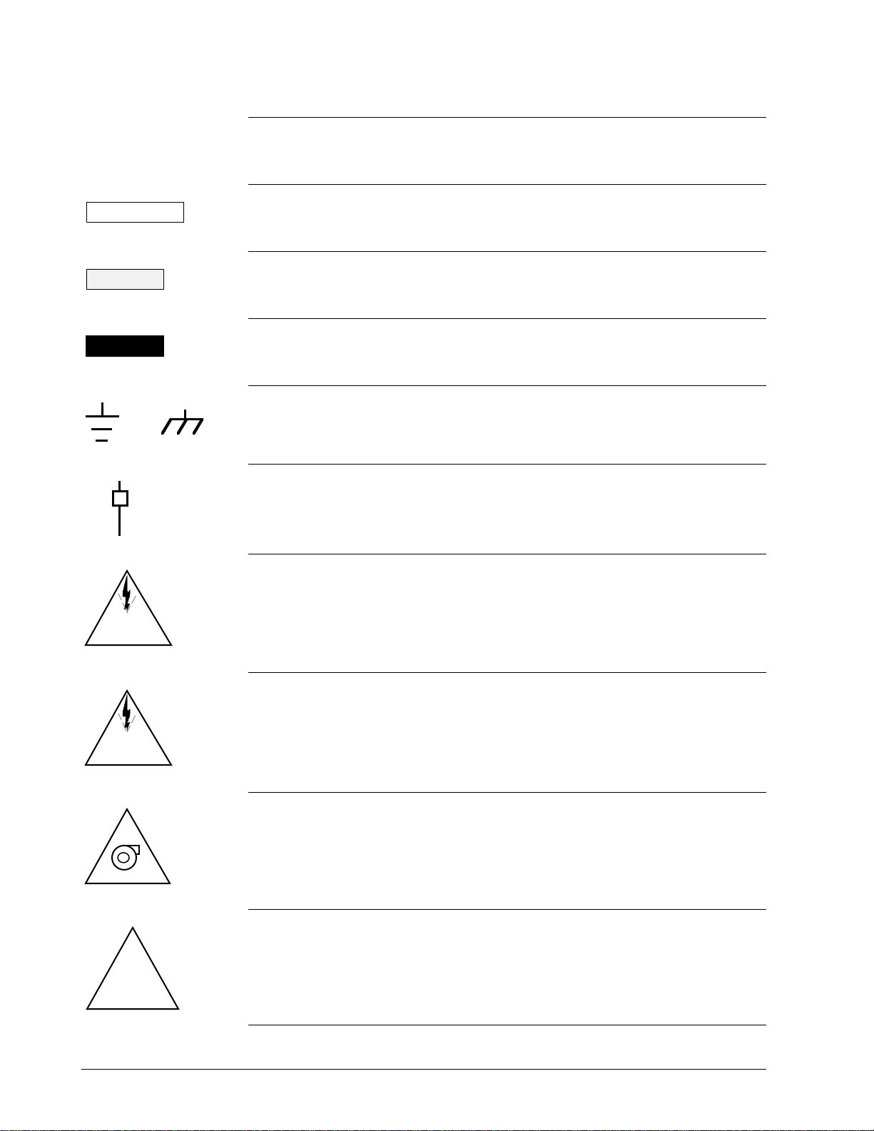
Standard Symbols
53896
Scope
ATTENTION
CAUTION
WARNING
OR
The standard symbols used in this publication are defined as follows.
Notes inform the reader about information that is required, but not
immediately evident.
Cautions tell the user that damage may occur to equipment if proper care is
not exercised.
Warnings tell the reader that potential personal harm or serious economic
loss may happen if instructions are not followed.
Ground connection to building safety ground.
53893
Ground stake for building safety ground.
53894
DANGER
SHOCK HAZARD
DANGER
HIGH VOLTAGE
!
Electrical Shock Hazard—can be lethal.
53895
Electrical Shock Hazard—can be lethal.
Rotating Fan—can cause personal injury.
53897
Caution—refer to the appropriate installation document.
iv HPM Planning 3/98
Page 7

Table of Contents
SECTION 1 – INTRODUCTION.................................................................................... 1
1.1 Overview.............................................................................................. 1
SECTION 2 – HPM DESCRIPTION.............................................................................. 3
2.1 Overview.............................................................................................. 3
2.2 Card Files ............................................................................................. 5
2.2.1 HPMM Card Files................................................................................... 6
2.2.2 Input/Output Processor (IOP) Card Files............................................... 12
2.3 Input/Output Processor (IOP) Cards..................................................... 16
2.3.1 IOP Redundancy................................................................................ 17
2.4 I/O Link Extender (Fiber Optic Link)...................................................... 19
2. 5 Field Termination Assemblies (FTAs).................................................... 24
2.6 Power Systems................................................................................... 36
2.7 Cabinet Configurations........................................................................ 41
SECTION 3 – POWER REQUIREMENTS.................................................................. 45
3.1 Overview............................................................................................ 45
3.2 Backup Strategy................................................................................. 46
3.3 Quality................................................................................................ 48
3.4 Power Draw ........................................................................................ 51
3.4.1 Typical 24 Vdc Power Draw Calculations ............................................... 53
3.4.2 Single Power System Calculation Example........................................... 58
3.4.3 Dual Power System Calculation Example .............................................. 59
3.4.4 HPM AC Power Draw........................................................................... 60
3.4.5 Crest Factor........................................................................................ 61
3.4.6 Inrush Current..................................................................................... 62
3.5 Substation Sizing................................................................................ 64
3.6 Circuit Breaker Sizing .......................................................................... 65
3.7 Custom UPS and Power Factor............................................................ 66
3.8 Automatic Bypass Switch..................................................................... 66
3. 9 Surge Protection ................................................................................ 67
3.10 Grounded Conductor .......................................................................... 68
3.11 Redundant Safety Grounds ................................................................. 68
3.12 Emergency Shutdown ........................................................................ 68
3.13 Trays and Conduits............................................................................. 68
3.14 Existing TPS System AC Power........................................................... 69
SECTION 4 – PROCESS WIRING.............................................................................. 71
4.1 Overview............................................................................................ 71
4.2 FTA Selection..................................................................................... 72
4.3 Cabinet Entry...................................................................................... 80
4.4 Signal Tray Wiring Compatibility............................................................ 81
4.5 Process Wiring Termination ................................................................. 82
SECTION 5 – HAZARDOUS ENVIRONMENT PLANNING........................................... 83
5.1 Overview............................................................................................ 83
5. 2 Hazardous Area Classifications............................................................. 84
5.3 Mounting and Operating the HPM in a Division 2 Location...................... 86
5.4 Field Wiring in Hazardous Locations ................................................... 100
SECTION 6 – CORROSION PROTECTION PLANNING ............................................ 103
6.1 Overview.......................................................................................... 103
6.2 Model Numbers................................................................................ 106
3/98 HPM Planning v
Page 8

Table of Contents
SECTION 7 – CE COMPLIANCE............................................................................. 115
7.1 Overview.......................................................................................... 115
7.2 Card Files ......................................................................................... 116
7.3 HPMM Cards..................................................................................... 117
7.4 IOPs................................................................................................. 117
7.5 FTAs................................................................................................ 120
7.6 I/O Link Extender.............................................................................. 129
7. 7 IOP to FTA Cables............................................................................. 130
7.8 Power Cables ................................................................................... 131
7.9 I/O Link Interface Cables.................................................................... 136
7.10 UCN Trunk Cable Taps...................................................................... 137
7.11 Cabinets........................................................................................... 139
SECTION 8 – MODEL MU-CBSM01/MU-CBDM01 CABINETS.................................. 141
8.1 Overview.......................................................................................... 141
8.2 Cabinet Description........................................................................... 144
8. 3 Card File and Power System Configurations........................................ 148
8. 4 Card File and Power System Description............................................. 150
8. 5 FTA Mounting Channel Description.................................................... 154
8.5.1 Vertical FTA Mounting Channels........................................................ 155
8.5.2 Horizontal FTA Mounting Channel...................................................... 159
8.6 Cabinet Floor Planning...................................................................... 163
SECTION 9 – MODEL MU-CBSX01/MU-CBDX01 CABINETS ................................... 165
9.1 Overview.......................................................................................... 165
9.2 Cabinet Description........................................................................... 169
9. 3 Card File and Power System Configurations........................................ 173
9. 4 Card File and Power System Description............................................. 175
9.5 FTA Mounting Channel Descriptions.................................................. 179
9.5.1 Vertical FTA Mounting Channels........................................................ 180
9.5.2 Horizontal FTA Mounting Channel...................................................... 184
9.6 Cabinet Floor Planning...................................................................... 188
SECTION 10 – REDUNDANCY PLANNING.............................................................. 189
10.1 Overview.......................................................................................... 189
10.2 Redundant HPMM Configurations...................................................... 189
10.3 Redundant IOP Placement ................................................................ 194
10.4 Redundancy Support........................................................................ 195
10.4.1 Power System.................................................................................. 195
10.4.2 HPMM to I/O ..................................................................................... 195
vi HPM Planning 3/98
Page 9

Table of Contents
SECTION 11 – I/O LINK EXTENDER PLANNING...................................................... 197
11.1 Overview.......................................................................................... 197
11.2 Description....................................................................................... 198
11.3 Fiber Optic Cable Routing.................................................................. 204
11.3.1 Direct Burial...................................................................................... 204
11.3.2 Aerial Lashing................................................................................... 204
11.3.3 Vertical Installations........................................................................... 205
11.3.4 Indoor Requirements........................................................................ 205
11.3.5 Loose Buffered Cable ....................................................................... 205
11.3.6 Number of Fibers.............................................................................. 206
11.3.7 Cable Installation............................................................................... 206
11.4 Indoor Cable Bend Radius................................................................. 207
11.5 Cable Construction........................................................................... 207
11.6 Cable Splices and Connections......................................................... 208
11.7 Signal Loss Budget........................................................................... 210
11.7.1 Standard I/O Link Extender................................................................ 210
11.7.2 Long Distance I/O Link Extender........................................................ 212
11.8 Power Level Measurement ................................................................ 213
SECTION 12 – LOW LEVEL MULTIPLEXER PLANNING.......................................... 215
12.1 Overview.......................................................................................... 215
12.2 LLMux Version................................................................................. 216
12.2.1 LLMux Configurations ....................................................................... 216
12.2.2 LLMux IOP Placement....................................................................... 219
12.2.3 LLMux Power Adapter Placement...................................................... 219
12.2.4 LLMux FTA Placement...................................................................... 219
12.2.5 Remote CJR Installation..................................................................... 222
12.3 RHMUX Version................................................................................ 223
12.3.1 RHMUX Configurations...................................................................... 223
12.3.2 RHMUX IOP Placement ..................................................................... 228
12.3.3 RHMUX Power Adapter Placement..................................................... 228
12.3.4 RHMUX FTA Placement..................................................................... 228
SECTION 13 – SERIAL DEVICE INTERFACE PLANNING......................................... 233
13.1 Overview.......................................................................................... 233
13.2 Serial Device Interface Configurations................................................ 233
13.3 Serial Device Interface IOP Placement................................................ 235
13.4 Power Adapter Placement................................................................. 235
13.5 IOP to Power Adapter Cabling............................................................ 235
13.6 Serial Device Interface FTA Placement............................................... 236
13.7 FTA to Power Adapter Cabling........................................................... 236
13.8 FTA Field Cabling.............................................................................. 238
13.9 Serial Device Interface FTA Models.................................................... 239
SECTION 14 – SERIAL INTERFACE PLANNING...................................................... 241
14.1 Overview.......................................................................................... 241
14.2 Serial Interface Configurations ........................................................... 241
14.3 Serial Interface IOP Placement........................................................... 247
14.4 Power Adapter Placement................................................................. 247
14.5 IOP to Power Adapter Cabling............................................................ 247
14.6 Serial Interface FTA Placement .......................................................... 248
14.7 FTA to Power Adapter Cabling........................................................... 248
14.8 FTA Field Cabling.............................................................................. 250
14.9 Serial Interface FTA Models............................................................... 251
14.10 Communications Interface Specifications............................................ 252
3/98 HPM Planning vii
Page 10

Table of Contents
SECTION 15 – GALVANICALLY ISOLATED FTA PLANNING.................................... 253
15.1 Overview.......................................................................................... 253
15.2 Description....................................................................................... 255
15.3 Features........................................................................................... 264
15.3.1 IOP Redundancy.............................................................................. 264
15.3.2 Analog and Digital Output Standby Manual Devices............................. 264
15.3.3 Auxiliary Inputs/Outputs.................................................................... 265
15.3.4 Power Requirements........................................................................ 267
15.3.5 Field Wiring Connections................................................................... 268
15.3.6 Ambient Temperature Limits.............................................................. 268
15.3.7 FTA Mounting Channels.................................................................... 269
15.4 Power Distribution............................................................................. 273
15.4.1 Power Distribution Assembly............................................................. 274
15.4.2 Cabling to Power Distribution Assemblies........................................... 275
15.4.3 Cabling to FTAs................................................................................ 275
15.4.4 Power Considerations ....................................................................... 276
15.5 High Level Analog Input (HLAI) FTAs.................................................. 277
15.5.1 Model MU-GAIH12/MU-GAIH82 FTA................................................... 277
15.5.1.1 Description....................................................................................... 277
15.5.1.2 Connectors...................................................................................... 277
15.5.1.3 Field Wiring Input Signals................................................................... 277
15.5.1.4 Auxiliary Connector Output................................................................ 278
15.5.1.5 Indicators.......................................................................................... 278
15.5.1.6 Current Consumption........................................................................ 278
15.5.1.7 Isolation and Safety........................................................................... 278
15.5.2 Model MU-GAIH13/MU-GAIH83 FTA................................................... 279
15.5.2.1 Description....................................................................................... 279
15.5.2.2 Connectors...................................................................................... 279
15.5.2.3 Field Wiring Input Signals................................................................... 280
15.5.2.4 Auxiliary Connector Output................................................................ 280
15.5.2.5 Indicators.......................................................................................... 280
15.5.2.6 Hand-Held Communicator.................................................................. 281
15.5.2.7 Current Consumption........................................................................ 281
15.5.2.8 Isolation and Safety........................................................................... 281
15.5.3 Model MU-GAIH14/MU-GAIH84 FTA................................................... 282
15.5.3.1 Description....................................................................................... 282
15.5.3.2 Connectors...................................................................................... 282
15.5.3.3 Field Wiring Input Signals................................................................... 283
15.5.3.4 Auxiliary Connector Output................................................................ 283
15.5.3.5 Indicators.......................................................................................... 283
15.5.3.6 Hand-Held Communicator.................................................................. 284
15.5.3.7 Current Consumption........................................................................ 284
15.5.3.8 Isolation and Safety........................................................................... 284
15.5.4 Model MU-GAIH22/MU-GAIH92 FTA................................................... 285
15.5.4.1 Description....................................................................................... 285
15.5.4.2 Connectors...................................................................................... 285
15.5.4.3 Field Wiring Input Signals................................................................... 286
15.5.4.4 Auxiliary Connector Output................................................................ 286
15.5.4.5 Indicators.......................................................................................... 286
15.5.4.6 Current Consumption........................................................................ 287
15.5.4.7 Isolation and Safety........................................................................... 287
viii HPM Planning 3/98
Page 11

Table of Contents
15.6 24 Vdc Digital Input FTAs................................................................... 288
15.6.1 Model MU-GDID12/MU-GDID82 FTA................................................... 288
15.6.1.1 Description....................................................................................... 288
15.6.1.2 Connectors...................................................................................... 288
15.6.1.3 Field Wiring Input Signals................................................................... 289
15.6.1.4 Line-Fault Detection.......................................................................... 289
15.6.1.5 Auxiliary Connector Output................................................................ 289
15.6.1.6 Indicators.......................................................................................... 290
15.6.1.7 Current Consumption........................................................................ 290
15.6.1.8 Isolation and Safety........................................................................... 290
15.6.2 Model MU-GDID13/MU-GDID83 FTA................................................... 291
15.6.2.1 Description....................................................................................... 291
15.6.2.2 Connectors...................................................................................... 291
15.6.2.3 Field Wiring Input Signals................................................................... 291
15.6.2.4 Indicators.......................................................................................... 292
15.6.2.5 Current Consumption........................................................................ 292
15.6.2.6 Isolation and Safety........................................................................... 292
15.7 Analog Output FTAs......................................................................... 293
15.7.1 Model MU-GAOX02/72 and MU-GAOX12/82 FTAs.............................. 293
15.7.1.1 Description....................................................................................... 293
15.7.1.2 Connectors...................................................................................... 293
15.7.1.3 Field Wiring Output Signals................................................................ 293
15.7.1.4 Line-Fault Detection.......................................................................... 294
15.7.1.5 Calibration........................................................................................ 294
15.7.1.6 Indicators.......................................................................................... 294
15.7.1.7 Current Consumption........................................................................ 294
15.7.1.8 Isolation and Safety........................................................................... 295
15.8 24 Vdc Digital Output FTAs................................................................ 296
15.8.1 Model MU-GDOD12/MU-GDOD82 FTA............................................... 296
15.8.1.1 Description....................................................................................... 296
15.8.1.2 Signal Connectors............................................................................ 296
15.8.1.3 Field Wiring Output Signals................................................................ 296
15.8.1.4 Auxiliary Connector........................................................................... 297
15.8.1.5 Indicators.......................................................................................... 297
15.8.1.6 Standby Manual Device Connector.................................................... 297
15.8.1.7 Current Consumption........................................................................ 298
15.8.1.8 Isolation and Safety........................................................................... 298
15.8.2 Model MU-GDOL12/MU-GDOL82 FTA............................................... 299
15.8.2.1 Description....................................................................................... 299
15.8.2.2 Signal Connectors............................................................................ 299
15.8.2.3 Field Wiring Output Signals................................................................ 299
15.8.2.4 Auxiliary Connector........................................................................... 300
15.8.2.5 Indicators.......................................................................................... 300
15.8.2.6 Standby Manual Device Connector.................................................... 301
15.8.2.7 Current Consumption........................................................................ 301
15.8.2.8 Isolation and Safety........................................................................... 301
15.9 Combiner Panel................................................................................ 302
15.10 Marshalling Panel.............................................................................. 303
15.10.1 Description....................................................................................... 303
15.10.2 Configurations.................................................................................. 304
15.10.2.1 High Level Analog Input FTAs............................................................ 304
15.10.2.2 Digital Input FTAs.............................................................................. 305
15.10.2.3 Digital Output FTAs........................................................................... 306
3/98 HPM Planning ix
Page 12

Figures
Figure 2-1 Nonredundant HPMM Cabinet Layout................................................. 4
Figure 2-2 Left 7-Slot HPMM Card File................................................................. 7
Figure 2-3 Right 7-Slot HPMM Card File............................................................... 9
Figure 2-4 15-Slot HPMM Card File.................................................................... 11
Figure 2-5 Left 7-Slot IOP Card File................................................................... 13
Figure 2-6 Right 7-Slot IOP Card File................................................................. 14
Figure 2-7 15-Slot IOP Card File........................................................................ 15
Figure 2-8 HLAI FTA with Redundant HLAI IOPs................................................ 17
Figure 2-9 Analog Output FTA with Redundant Analog Output IOPs................... 18
Figure 2-10 Standard I/O Link Extender Interconnections
with Nonredundant HPMM................................................................ 20
Figure 2-11 Standard I/O Link Extender Interconnections
with Redundant HPMMs................................................................... 21
Figure 2-12 Long Distance I/O Link Extender Interconnections
with Nonredundant HPMM................................................................ 22
Figure 2-13 Long Distance I/O Link Extender Interconnections
with Redundant HPMMs................................................................... 23
Figure 2-14 Field Termination Assembly (FTA) Sizes............................................ 28
Figure 2-15 Typical Vertical FTA Mounting Channel Layout................................... 30
Figure 2-16 Typical FTA Compression Terminal Connector................................... 31
Figure 2-17 Typical FTA Fixed-Screw Terminal Connector .................................... 32
Figure 2-18 Typical FTA Removable-Screw Terminal Connector............................ 32
Figure 2-19 Crimp-Pin Galvanic Isolation Module Terminal Connector.................... 33
Figure 2-20 Compression-Type Galvanic Isolation Module .................................... 34
Figure 2-21 FTA Marshalling Panel Assembly Layout............................................ 35
Figure 2-22 Standard Power System—Model MU-PSRX03................................... 37
Figure 2-23 Standard Power System—Model MU-PSRX04................................... 38
Figure 2-24 AC Only Power System—Not for CE Compliant Applications............... 40
Figure 2-25 Single Cabinet with Redundant HPMMs............................................ 42
Figure 2-26 Complexed Cabinets with Redundant HPMMs................................... 43
Figure 2-27 Local Complexed Cabinets with Redundant HPMMs .......................... 44
Figure 3-1 Subsystem AC Power and Ground Connections—
Multi-Ground System........................................................................ 49
Figure 3-2 Subsystem AC Power and Ground Connections—
Single-Ground System ..................................................................... 50
Figure 4-1 Field Termination Assembly (FTA) Sizes............................................ 73
Figure 4-2 Field Termination Assembly (FTA) Mounting Dimensions.................... 74
Figure 6-1 Conformal Coating Symbol............................................................. 105
Figure 7-1 I/O Link Extender Adapter Kit.......................................................... 129
Figure 7-2 Two-Port UCN Cable Tap................................................................ 137
Figure 7-3 Four-Port UCN Cable Tap............................................................... 138
Figure 7-4 Eight-Port UCN Cable Tap.............................................................. 138
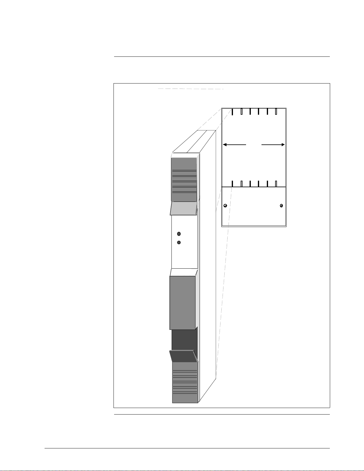
Figure 8-1 Single-Access Cabinet ................................................................... 142
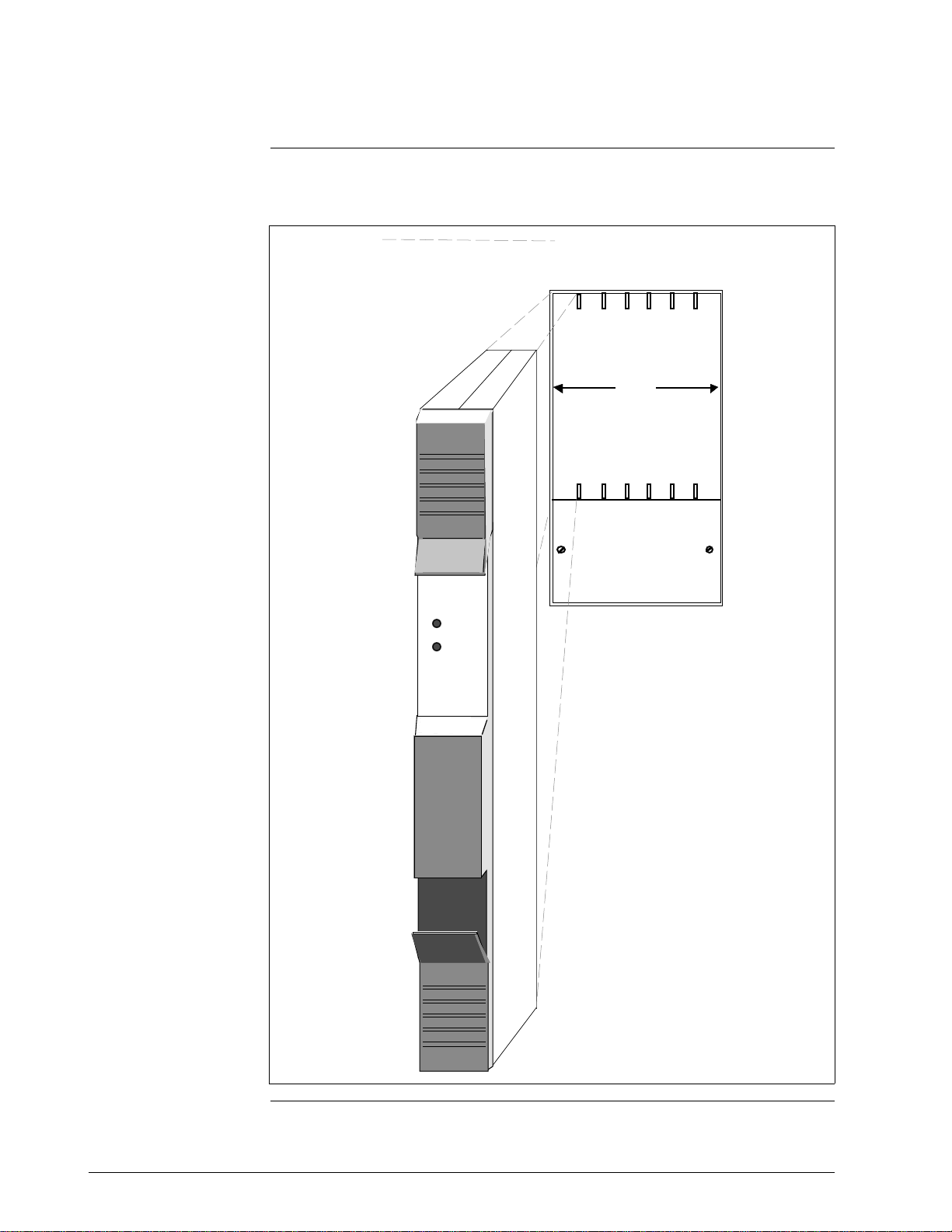
Figure 8-2 Dual-Access Cabinet...................................................................... 143
Figure 8-3 Single-Access Cabinet Bottom Cable Entry Slots ............................. 144
Figure 8-4 Dual-Access Cabinet Bottom Cable Entry Slots................................ 145
Figure 8-5 Cabinet Interior Dimensions............................................................ 147
Figure 8-6 Typical Single-Access Cabinet Assembly Layout.............................. 148
Figure 8-7 Typical Dual-Access Cabinet Assembly Layout................................. 149
Figure 8-8 7-Slot Card File Installation Dimensions............................................ 150
Figure 8-9 15-Slot Card File Installation Dimensions.......................................... 151
Figure 8-10 Installation of 7-Slot and 15-Slot Card Files....................................... 152
Figure 8-11 Power System Installation Dimensions............................................. 153
Figure 8-12 Typical Vertical FTA Mounting Channel Configurations..................... 156
Figure 8-13 Vertical FTA Mounting Channel Dimensions .................................... 157
Figure 8-14 Vertical FTA Mounting Channel Installation Holes............................. 158
Figure 8-15 Horizontal FTA Mounting Channel Cabinet Layout ........................... 160
Figure 8-16 Horizontal FTA Mounting Channel Dimensions ................................ 161
x HPM Planning 3/98
Page 13

Figures
Figure 8-17 Horizontal FTA Mounting Channel Installation Holes......................... 162
Figure 8-18 Cabinet Floor Planning Template .................................................... 163
Figure 9-1 Single-Access Cabinet................................................................... 166
Figure 9-2 Dual-Access Cabinet...................................................................... 167
Figure 9-3 Cabinet Base Panel Grounding Procedure ...................................... 168
Figure 9-4 Cabinet Panel and Door Grounding Procedure ................................ 168
Figure 9-5 Single-Access Cabinet Bottom Cable Entry ..................................... 169
Figure 9-6 Dual-Access Cabinet Bottom Cable Entry........................................ 170
Figure 9-7 Cabinet Interior Dimensions............................................................ 172
Figure 9-8 Typical Single-Access Cabinet Assembly Layout.............................. 173
Figure 9-9 Typical Dual-Access Cabinet Assembly Layout................................. 174
Figure 9-10 7-Slot Card File Installation Dimensions............................................ 175
Figure 9-11 15-Slot Card File Installation Dimensions.......................................... 176
Figure 9-12 Installation of 7-Slot and 15-Slot Card Files....................................... 177
Figure 9-13 Power System Installation Dimensions............................................. 178
Figure 9-14 FTA Mounting Channel Configurations............................................ 181
Figure 9-15 FTA Mounting Channel Dimensions ................................................ 182
Figure 9-16 FTA Mounting Channel Mounting FTA Installation Holes................... 183
Figure 9-17 Horizontal FTA Mounting Channel Cabinet Layout ........................... 185
Figure 9-18 Horizontal FTA Mounting Channel Dimensions ................................ 186
Figure 9-19 Horizontal FTA Mounting Channel Installation Holes......................... 187
Figure 9-20 Cabinet Floor Planning Template .................................................... 188
Figure 10-1 Single Cabinet with Redundant HPMMs.......................................... 191
Figure 10-2 Dual Cabinets with Redundant HPMMs............................................ 192
Figure 10-3 Redundant HPMM Configuration Cabling ........................................ 193
Figure 10-4 Local/Remote Cabinet Configuration............................................... 196
Figure 11-1 Standard I/O Link Extender Interconnections
with Single HPMM.......................................................................... 199
Figure 11-2 Standard I/O Link Extender Interconnections
with Redundant HPMMs................................................................. 200
Figure 11-3 Long Distance I/O Link Extender Interconnections
with Single HPMM.......................................................................... 201
Figure 11-4 Long Distance I/O Link Extender Interconnections
with Redundant HPMMs................................................................. 202
Figure 11-5 Remote Site Multi-IOP Card File I/O Link Interface Cabling................. 203
Figure 11-6 ST-Type Connector....................................................................... 209
Figure 12-1 LLMux Configuration Interconnections – CE Compliant.................... 218
Figure 12-2 Remote CJR Installation.................................................................. 222
Figure 12-3 Nonincendive RHMUX Configuration Interconnections..................... 226
Figure 12-4 Intrinsically Safe RHMUX Configuration Interconnections.................. 227
Figure 13-1 Serial Device Interface Interconnections.......................................... 234
Figure 14-1 Serial Interface FTA to Modbus Device EIA-232 and EIA-422/485
Interconnections............................................................................ 243
Figure 14-2 Serial Interface FTA to Modbus Device EIA-422/485
Interconnections............................................................................ 244
Figure 14-3 Serial Interface FTA to Peripheral Device EIA-422/485
Interconnections............................................................................ 245
Figure 14-4 Serial Interface FTA to Allen-Bradley Device EIA-232
Interconnections............................................................................ 246
Figure 15-1 Typical Galvanically Isolated FTA...................................................... 259
Figure 15-2 Galvanic Isolation Module................................................................ 260
Figure 15-3 Crimp-Type Galvanic Isolation Module Terminal Connector................ 261
Figure 15-4 Compression-Type Galvanic Isolation Module Terminal Connector .... 262
Figure 15-5 Galvanically Isolated FTA with Auxiliary Connector............................ 266
Figure 15-6 Cabinet with Horizontally Installed FTA Mounting Channels............... 270
3/98 HPM Planning xi
Page 14

Tables
Table 2-1 Card File Models ................................................................................ 5
Table 2-2 Standard Field Termination Assembly Types...................................... 25
Table 2-3 Galvanically Isolated Field Termination Assembly Types...................... 27
Table 3-1 HPM Assembly 24 Vdc Power Usage ................................................ 54
Table 3-2 Single Power System Calculation Example ........................................ 58
Table 3-3 Dual Power System Calculation Example (Power System 1)................ 59
Table 3-4 Dual Power System Calculation Example (Power System 2)................ 60
Table 4-1 Standard FTAs and Associated Assemblies....................................... 75
Table 4-2 Galvanically Isolated FTAs and Associated Assemblies ....................... 78
Table 5-1 Hazardous Area Classifications.......................................................... 84
Table 5-2 HPM Equipment Approved for Use in a Division 2 Area....................... 87
Table 5-3 Nonincendive FTA Types ............................................................... 101
Table 5-4 FTA Cable and Load Parameters..................................................... 102
Table 6-1 Environment Minimum Equipment Requirement .............................. 103
Table 6-2 Harsh Environment Definitions from ANSI/ISA-S71.04-1985............ 104
Table 6-3 Conformally Coated Assembly Model Numbers................................ 107
Table 7-1 Card Files ...................................................................................... 116
Table 7-2 IOPs—Nonconformally Coated ....................................................... 118
Table 7-3 IOPs—Conformally Coated............................................................. 119
Table 7-4 Field Termination Assemblies—Nonconformally Coated................... 120
Table 7-5 Field Termination Assemblies—Conformally Coated......................... 125
Table 7-6 IOP to FTA Cables.......................................................................... 130
Table 7-7 Non-CE Compliant Subsystem Power Cables .................................. 133
Table 7-8 CE Compliant Subsystem Power Cables.......................................... 134
Table 7-9 Power Cables without I/O Link Protector Module.............................. 135
Table 7-10 I/O Link Interface Cable Sets........................................................... 136
Table 11-1 Minimum Bend Radius for Indoor Cable ........................................... 207
Table 11-2 Standard Optical Power Loss.......................................................... 211
Table 11-3 Standard Fiber Optic Cable Losses (@ 850 nm) ............................... 211
Table 11-4 Long Distance Optical Power Loss.................................................. 213
Table 11-5 Long distance Fiber Optic Cable Losses (@ 1300 nm)...................... 213
Table 12-1 LLMux Assembles......................................................................... 216
Table 12-2 RHMUX Assemblies ....................................................................... 223
Table 14-1 Serial Interface FTAs ...................................................................... 241
Table 14-2 Serial Interface EIA-232 Specifications ............................................ 252
Table 14-3 Serial Interface EIA-422/485 Specifications ..................................... 252
Table 15-1 CE Compliant Galvanically Isolated FTAs—Nonconformally Coated ... 256
Table 15-2 CE Compliant Galvanically Isolated FTAs—Conformally Coated ......... 257
Table 15-3 Galvanically Isolated FTA Power Requirements................................ 267
xii HPM Planning 3/98
Page 15

Acronyms
AC.................................................................................................. Alternating Current
ANSI.................................................................... American National Standards Institute
AO........................................................................................................ Analog Output
AWG........................................................................................... American Wire Gauge
CJR........................................................................................ Cold Junction Reference
CMOS ........................................................ Complementary Metal Oxide Semiconductor
DC.......................................................................................................... Direct Current
DISOE........................................................................ Digital Input Sequence of Events
DI............................................................................................................... Digital Input
DO.......................................................................................................... Digital Output
EIA.............................................................................. Electronic Industries Association
EMI.................................................................................. Electromagnetic Interference
FM................................................................................... Factory Mutual Research, Inc.
FTA.................................................................................... Field Termination Assembly
GI ....................................................................................................... Galvanic Isolation
HLAI......................................................................................... High Level Analog Input
HPM...................................................................... High-Performance Process Manager
HPMM....................................................... High-Performance Process Manager Module
IS........................................................................................................... Intrinsic Safety
I/O............................................................................................................ Input/Output
IEC................................................................ International Electrotechnical Commission
IEEE.................................................... Institute of Electrical and Electronic Engineering
ISA.................................................................................. Instrument Society of America
ISO....................................................................... International Standards Organization
LCN............................................................................................ Local Control Network
LFD............................................................................................... Line Fault Detection
LLAI ......................................................................................... Low Level Analog Input
LLMux..................................................................... Low Level Analog Input Multiplexer
MRG...................................................................................... Master Reference Ground
NE........................................................................................... National Electrical Code
NEMA....................................................... National Electrical Manufacturer’s Association
NFPA........................................................................... National Fire Protection Agency
NiCad................................................................................................... Nickel Cadmium
NIM....................................................................................... Network Interface Module
PI............................................................................................................... Pulse Input
PSM........................................................................................... Power Supply Module
PS ......................................................................................................... Power System
PVC.................................................................................................. Polyvinyl Chlorine
PV ..................................................................................................... Process Variable
RHMUX ....................................... Remote Hardened Low Level Analog Input Multiplexer
RTD................................................................................ Resistive Temperature Device
RTU............................................................................................ Remote Terminal Unit
SDI............................................................................................. Serial Device Interface
SI.......................................................................................................... Serial Interface
STI....................................................................................... Smart Transmitter Interface
STIM ................................................................. Smart Transmitter Interface Multivariable
TC......................................................................................................... Thermocouple
UCN...................................................................................... Universal Control Network
UV.............................................................................................................. Ultra Violet
3/98 HPM Planning xiii
Page 16

References
Publication
Title
High-Performance Process Manager
Specification and Technical Data
High-Performance Process Manager
Installation
High-Performance Process Manager
Checkout
High-Performance Process Manager
Service
Process Manager I/O Specification and
Technical Data
Process Manager I/O Installation
TPS System Site Planning
Publication
Number
HP03-500 System Summary - 2 TPS 3010-2
HP20-500 Implementation/
High-Performance Process
Manager - 3
HP20-510 Implementation/
High-Performance Process
Manager - 3
HP13-500 PM/APM/HPM Service - 1 TPS 3061-1
IO03-500 System Summary - 2 TPS 3010-2
PM20-520 Implementation/
High-Performance Process
Manager - 3
SW02-550 System Site Planning - 1 TPS 3020-1
Binder
Title
Binder
Number
TPS 3066-3
TPS 3066-3
TPS 3066-3
Universal Control Network Specification
and Technical Data
Universal Control Network Planning
Universal Control Network Installation
Universal Control Network Guidelines
Local Control Network Planning
LCN System Installation
LCN System Checkout
LCN Guidelines - Implementation,
Troubleshooting, and Service
UN03-500 System Summary - 2 TPS 3010-2
UN02-501 System Site Planning - 1 TPS 3020-1
UN20-500 Installation/Universal Control
Network
UN12-510 Installation/Universal Control
Network
SW02-501 System Site Planning - 1 TPS 3020-1
SW20-500 LCN Installation TPS 3025
SW20-510 LCN Installation TPS 3025
LC09-510 LCN Installation TPS 3025
TPS 3041
TPS 3041
xiv HPM Planning 3/98
Page 17

1.1 Overview
Section 1 – Introduction
Section contents
1. 1 Overview............................................................................................... 1
The manual’s purpose
The manual’s contents
The topics covered in this section are:
Topic See Page
This manual is intended for planning the installation of a High-Performance
Process Manager (HPM) subsystem at a TPS
system site. The
High-Performance Process Manager subsystem is a device on the Universal
Control Network (UCN) that includes the Network Interface Module
(NIM). Process Managers (PMs), Advanced Process Managers (APMs),
and Logic Managers (LMs) may also be resident on the network.
Planning includes the consideration of the High-Performance Process
Manager cabinet layout, process wiring techniques, Division 2 environment
equipment approval, conformal coating of the assemblies to protect against
a corrosive environment, HPMM and IOP redundancy, and unique
hardware features, such as fiber optic I/O Link Extenders, Low Level
Analog Input Multiplexer FTAs, Serial Device Interface FTAs, Serial
Interface FTAs, and Galvanically Isolated FTAs.
Information not covered
Neither installation, power on checkout, or service of the
High-Performance Process Manager, nor planning for the Local Control
Network (LCN) is addressed in this manual. See the related reference
documentation for information about these topics.
3/98 HPM Planning 1
Page 18

2 HPM Planning 3/98
Page 19

2.1 Overview
Section 2 – HPM Description
Section contents
2. 1 Overview............................................................................................... 3
2.2 Card Files.............................................................................................. 5
2.2.1 HPMM Card Files ................................................................................... 6
2.2.2 Input/Output Processor (IOP) Card Files................................................ 13
2. 3 Input/Output Processor (IOP) Cards...................................................... 17
2.3.1 IOP Redundancy ................................................................................. 18
2. 4 I/O Link Extender (Fiber Optic Link)....................................................... 20
2.5 Field Termination Assemblies (FTAs) .................................................... 25
2.6 Power Systems................................................................................... 36
2. 7 Cabinet Configurations ........................................................................ 41
HPM major assemblies
The topics covered in this section are:
Topic See Page
The High-Performance Process Manager subsystem (HPM) consists of
major assemblies described in the following subsections. The major
High-Performance Process Manager assemblies are
• High-Performance Process Manager Module (HPMM) card file
• Input/Output Processor (IOP) card file
• Input/Output Processor (IOP) card
• I/O Link Extender
• Field Termination Assembly (FTA)
• Power System
Continued on next page
3/98 HPM Planning 3
Page 20
2.1 Overview, Continued
P
P
P
Digital
P
P
P
High L
l
Anal
L
l
Digital
P
Digital
P
P
P
P
High L
l
Anal
L
l
Digital
P
Digital
P
P
P
P
High L
l
Anal
L
l
Digital
P
P
Digital
P
P
P
High L
l
Anal
L
l
Digital
P
Digital
P
P
P
P
High L
l
Anal
L
l
Digital
P
Digital
P
P
P
P
High
High
L
l
Digital
P
P
Nonredundant HPM
cabinet layout
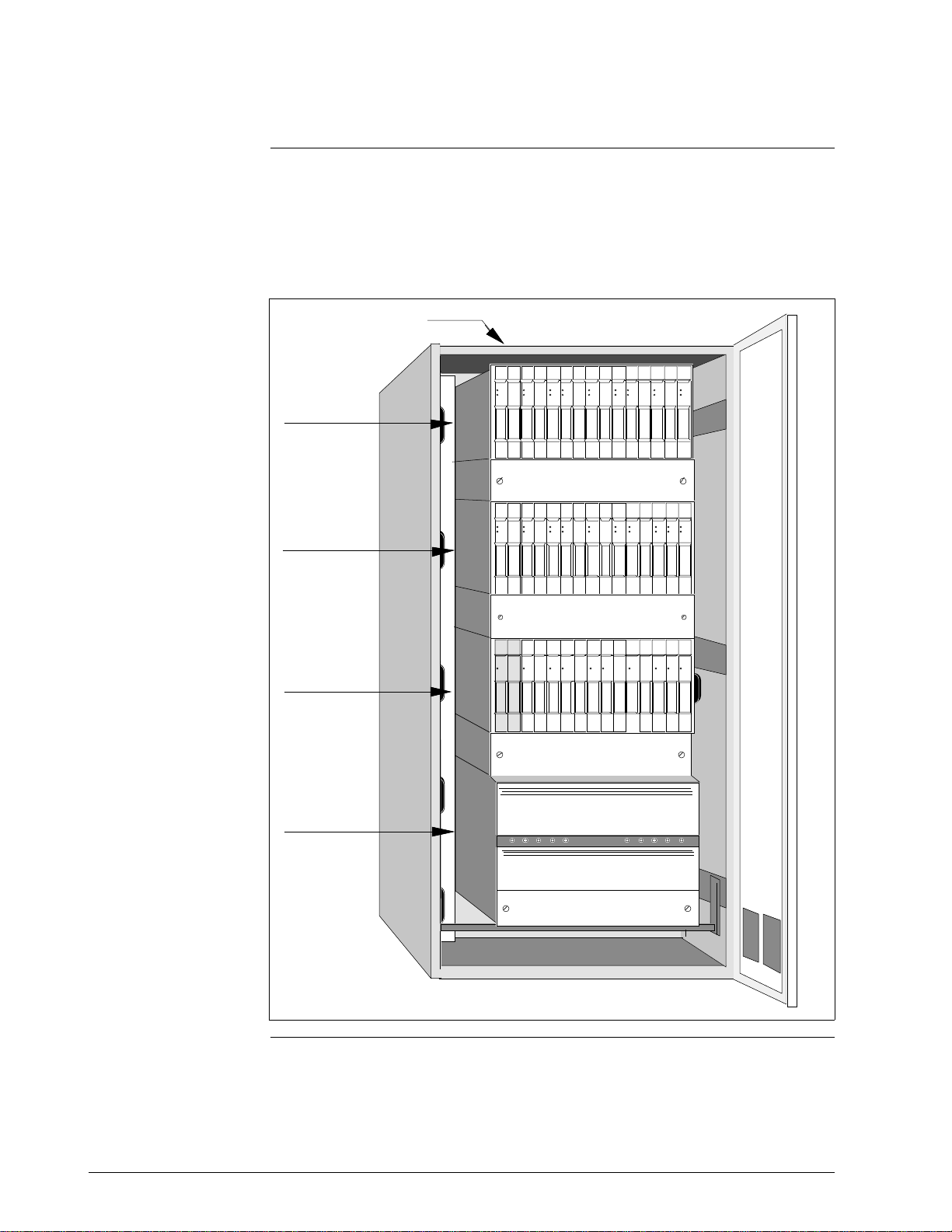
Figure 2-1 is an illustration of a single High-Performance Process Manager
cabinet containing a nonredundant High-Performance Process Manager
Module (HPMM) with supporting assemblies. The HPMM cards (2) and
the IOPs cards are installed in 15-Slot HPMM card files. IOP cards occupy
the IOP card files.
Figure 2-1 Nonredundant HPMM Cabinet Layout
FTAs are installed in the
rear on an FTA Mounting
Channel.
ower
Power
Power
Power
Status
Status
Status
Status
Analog
Low Level
Digital
Digital
Output
Analog
Input
Output
Input
ower
ower
ower
ower
Status
Status
Status
Status
og
ow Leve
Output
Input
Analog
Output
Input
IOP Card File #2
IOP Card File #1
ower
ower
Power
Power
Status
Status
High Level
Analog
Analog
Input
Output
ower
ower
Status
Status
eve
og
Output
Analog
Input
Power
Power
Power
Status
Status
Status
Status
Status
Low Level
Analog
Input
ower
Status
ow Leve
Analog
Input
Analog
High Level
Digital
Digital
Output
Analog
Input
Output
Input
ower
ower
ower
ower
Status
Status
Status
Status
eve
og
Output
Analog
Input
Output
Input
Power
Power
Power
Power
Status
Status
Status
Status
Low Level
High Level
Digital
Digital
Analog
Analog
Input
Output
Input
Input
ower
ower
ower
ower
Status
Status
Status
Status
eve
ow Leve
Analog
Input
Analog
Output
Input
Input
HPMM Card File
Power System
Performan
Comm/Cntl
ower
ower
ower
ower
ower
ower
ower
ower
ower
ower
ower
ower
Status
Status
Status
Status
Status
ow Leve
Analog
Input
Performan
Analog
Output
I/O Link
Input
Input
ower
Status
Status
Status
Status
Status
eve
og
ow Leve
Output
Analog
Input
Analog
Output
Input
Input
ower
Status
eve
ower
Status
Status
Status
Status
og
ow Leve
Output
Input
Analog
Output
Input
32747
4 HPM Planning 3/98
Page 21

2.2 Card Files
Introduction
There are nine card file models. Three models are not CE Compliant and
six models are CE Compliant. Table 2-1 lists the nine card file models. All
models are also available with conformal coating (a model number with a
prefix of MC, rather than MU).
Table 2-1 Card File Models
Card File Description CE Compliant Non-CE Compliant
Left 7-Slot HPMM or IOP N/A MU-HPFH01
Right 7-Slot HPMM or IOP N/A MU-HPFH11
15-Slot HPMM or IOP N/A MU-HPFX02
Left 7-Slot HPMM MU-HPFH03 N/A
Right 7-Slot HPMM MU-HPFH13 N/A
15-Slot HPMM MU-HPFX03 N/A
Left 7-Slot IOP MU-HPFI03 N/A
Right 7-Slot IOP MU-HPFI13 N/A
15-Slot IOP MU-HPFI23 N/A
Non-CE Compliant card
file models
CE Compliant card file
models
Conversion kit
The non-CE Compliant card file models can be designated as an HPMM
card file or an IOP card file by either installing an HPMM card set in the
two left-most card slots or installing IOP cards.
Unlike the non-CE Compliant card file models, the CE Compliant card file
models are designated either an HPMM card file or an IOP card file because
even though their is no electrical difference in the backpanel, they differ
mechanically. The addition of a ground plate and filtered IOP connectors in
the two left-most slots prohibits the installation of an HPMM card set.
The card file is designated an IOP card file when the ground plate and
filtered connectors are present.
The card file is designated an HPMM card file when the ground plate and
filtered connectors are absent.
A CE Compliant HPMM card file can be converted to an IOP card file with
a model MU-ZPFI03 upgrade kit. The kit adds 2 filtered IOP adapter
connectors to the two left-most card slots and a ground plate extension.
3/98 HPM Planning 5
Page 22

2.2.1 HPMM Card Files
Three types of HPM
card files
HPMM description
There are three types of HPMM card files. The two left-most slots of each
type are populated by the three assemblies that comprise the HPMM. The
remaining slots accommodate IOPs.
If the card file is a non-CE Compliant card file, the two left-most slots of
each type can also accommodate IOPs with no alterations. The card file is
then designated an IOP card file.
The High-Performance Process Manager Module (HPMM) is composed of
two card assemblies that install in the two left-most slots in a 7-Slot or
15-Slot card file, and a UCN interface module that mounts and connects to
the 50-pin connector that is directly below the left-most card.
The three HPMM assemblies are identified as follows:
• High-Performance Communications/Control (High-Performance
Comm/Control) card
• High-Performance I/O Link Interface (High-Performance I/O Link) card
• High-Performance UCN Interface (HPM UCN Interface) module
The HPM UCN Interface module connects to the 50-pin connector below
the High-Performance Comm/Control card.
Left 7-Slot HPMM card
file description
The Left 7-Slot card file accepts the two HPMM cards and the HPM UCN
Interface module that comprise the HPMM, and accommodates up to five
IOP cards. The card slots are numbered 1 through 7, starting at the
left-most position.
The High-Performance Comm/Control and High-Performance I/O Link
cards occupy slots 1 and 2, while the HPM UCN Interface module mounts
below slot 1 and connects to its 50-pin connector.
Slots 3 through 7 can accommodate IOP cards. The IOP card slots assume
numerical I/O Link Interface addresses of 3 through 7 and binary I/O Link
Interface addresses of 2 through 6.
Continued on next page
6 HPM Planning 3/98
Page 23
2.2.1 HPMM Card Files, Continued
Left 7-Slot HPMM
card file illustration
Figure 2-2 is an illustration of a Left 7-Slot HPMM card file and the two
HPMM cards that occupy slots 1 and 2.
Figure 2-2 Left 7-Slot HPMM Card File
1A15
Power
Status
High
Performance
Comm/Cntrl
Power
Status
High
Performance
I/O Link
HPMM
1 2 3 4 5 6 7
IOPs
16000
Continued on next page
3/98 HPM Planning 7
Page 24

2.2.1 HPMM Card Files, Continued
Right 7-Slot HPMM card
file description
The description of the Right 7-Slot HPMM card file is identical to the Left
7-Slot HPMM card file, except the two HPMM cards and the UCN
interface module occupy slots 9 and 10. The card slots are numbered
9 through 15.
Slots 11 through 15 accommodate IOP cards. The IOP card slots assume
numerical I/O Link Interface addresses of 11 through 15 and binary
I/O Link Interface addresses of 10 through 14.
Continued on next page
8 HPM Planning 3/98
Page 25

2.2.1 HPMM Card Files, Continued
Right 7-Slot HPMM
card file illustration
Figure 2-3 is an illustration of a Right 7-Slot HPMM card file and the two
HPMM cards that occupy slots 9 and 10.
Figure 2-3 Right 7-Slot HPMM Card File
1A15
Power
Status
High
Performance
Comm/Cntrl
Power
Status
High
Performance
I/O Link
HPMM
9 10 11 12 13 14 15
IOPs
16001
Continued on next page
3/98 HPM Planning 9
Page 26

2.2.1 HPMM Card Files, Continued
15-Slot HPMM card file
description
The 15-Slot card file accepts the two HPMM cards and the UCN interface
module that comprise the HPMM, and accommodates up to thirteen IOP
cards. The card slots are numbered 1 through 15, starting at the left-most
position.
The High-Performance Comm/Control and High-Performance I/O Link
cards occupy slots 1 and 2, while the HPM UCN Interface module mounts
below slot 1 in its 50-pin connector.
Slots 3 through 15 can accommodate IOP cards. The IOP card slots
assume numerical I/O Link Interface addresses of 3 through 15 and binary
I/O Link Interface addresses of 2 through 14.
When populated with the HPMM cards, the card file is designated a 15-Slot
HPMM card file.
Continued on next page
10 HPM Planning 3/98
Page 27
2.2.1 HPMM Card Files, Continued
r
s
r
s
15-Slot HPMM
card file illustration
Figure 2-4 is an illustration of a 15-Slot HPMM card file and the two
HPMM cards that occupy slots 1 and 2.
Figure 2-4 15-Slot HPMM Card File
Powe
Statu
High
Performance
Comm/Cntrl
Powe
Statu
High
Performance
I/O Link
HPMM
1 2 3 4 5 6 7 8 9 10 11 12 13 14 15
IOPs
32745
Continued on next page
3/98 HPM Planning 11
Page 28

2.2.1 HPMM Card Files, Continued
7-Slot HPMM card file
usage
15-Slot HPMM card file
usage
HPMM functionality
The two types of 7-Slot HPMM card files are intended to be used in a small
HPM subsystem.
When the subsystem consists of nonredundant HPMMs, a Left 7-Slot
HPMM card file must be installed. For a subsystem that requires redundant
HPMMs, Left and Right 7-Slot HPMM card files are installed. Both card
files are assigned the same the same I/O Link Interface address. There is no
slot 8 because the card file slots are numbered 1 through 7 and 9 through
15.
The 15-Slot HPMM card file is intended for use in a larger HPM
subsystem, either with nonredundant or redundant HPMMs. Unlike the
7-Slot HPMM card file, there is no “loss” of a card slot.
The HPMM provides the following functions:
• Communications with the Local Control Network (LCN) Network
Interface Module (NIM) through the Universal Control Network (UCN)
• A Communications processor ( Motorola 68LC040)
• Communications through the I/O Link Interface with Input/Output
Processors (IOPs) and I/O Link Extenders
• A Control processor (Motorola 68040)
• Separate and shared memory for the Communications and Control
processors
• An I/O Link processor (Intel 80C32) with SRAM
• HPMM redundancy control
2.2.2 Input/Output Processor (IOP) Card Files
IOP card file
descriptions
Non-CE Compliant card
files
CE Compliant card files
The 7-Slot and 15-Slot IOP card files are electrically identical to the HPMM
card files, except that an HPMM card set is not installed in the card file.
IOPs can be installed in the two left-most card slots.
Non-CE Compliant HPMM and IOP card files differ only in the application.
Electrically and mechanically, their backpanels are the same. The card file
model numbers are the same.
CE Compliant HPMM and IOP card files differ mechanically. IOP card
files have filtered IOP connectors and connector ground plates. Electrically,
their backpanels are the same. The card file model numbers are different.
Continued on next page
12 HPM Planning 3/98
Page 29
2.2.2 Input/Output Processor (IOP) Card Files, Continued
Left 7-Slot IOP card file
Figure 2-5 illustrates a Left 7-Slot IOP card file.
Figure 2-5 Left 7-Slot IOP Card File
7 IOPs
1234567
Power
Status
Analog
Output
16004
Continued on next page
3/98 HPM Planning 13
Page 30
2.2.2 Input/Output Processor (IOP) Card Files, Continued
5
Right 7-Slot IOP card
file
Figure 2-6 illustrates a Left 7-Slot IOP card file.
Figure 2-6 Right 7-Slot IOP Card File
7 IOPs
9 10111213141
Power
Status
Analog
Output
16005
Continued on next page
14 HPM Planning 3/98
Page 31

2.2.2 Input/Output Processor (IOP) Card Files, Continued
15-Slot IOP card file
Figure 2-7 illustrates a 15-Slot IOP card file.
Figure 2-7 15-Slot IOP Card File
15 IOPs
123456789101112131415
Power
Status
Analog
Output
32962
3/98 HPM Planning 15
Page 32

2.3 Input/Output Processor (IOP) Cards
Types of Input/Output
Processors (IOPs)
Card file configurations
There are thirteen types of Input/Output Processor (IOP) card assemblies.
Some IOP card types interface with more than one type of Field
Termination Assembly (FTA). The functional types of IOPs are
• High Level Analog Input (HLAI)
• Low Level Analog Input (LLAI)
• Low Level Analog Multiplexer (LLMux)
• Remote Hardened Low Level Analog Multiplexer (RHMUX)
• Digital Input (DI)
• Analog Output (AO)
• Digital Output (DO)
• Smart Transmitter Interface (STI)
• Smart Transmitter Interface Multivariable (STIM)
• Pulse Input (PI)
• Digital Input Sequence of Events (DISOE)
• Serial Device Interface (SDI)
• Serial Interface (SI)
Additional IOP card file slots can be added to any High-Performance
Process Manager subsystem. Each IOP card file accommodates up to 7 or
15 IOPs as illustrated in Figures 2-5 through 2-7. A total of eight 15-Slot
card files or 7-Slot card file pairs (Left and Right), including HPMM card
files, can exist in a High-Performance Process Manager subsystem.
However, the limit is eight because each 15-Slot card file and pair of 7-Slot
card files must be assigned an I/O Link Interface address between 0 and 7.
IOP card files can be installed at remote locations with the use of fiber optic
I/O Link Extenders, as well as locally in the cabinet or cabinet complex
containing the HPMM card file(s).
A total of 40 primary IOPs, 40 secondary (redundant) IOPs, and 3 I/O Link
Extenders (a maximum of 8 I/O Link Extender cards) can exist in a single
High-Performance Process Manager subsystem.
16 HPM Planning 3/98
Page 33

2.3.1 IOP Redundancy
IOP redundancy
Redundant HLAI IOPs
The HPM subsystem supports IOP redundancy for the following types of
IOPs:
• High Level Analog Input (HLAI)
• Smart Transmitter Interface (STI or STIM)
• Analog Output (AO)
• Digital Input (DI)
• Digital Input Sequence of Events (DISOE)
• Digital Output (DO)
Presently, not all Digital Input and Digital Output IOP models support
redundancy.
A pair of IOPs can be connected in a redundant configuration with both
IOPs connected by separate cables to the same FTA. Figure 2-8 illustrates
an HLAI FTA that interfaces with a pair of HLAI IOPs that are installed in
separate card files.
Figure 2-8 HLAI FTA with Redundant HLAI IOPs
Primary
HPMM Card File
Secondary
HPMM Card File
J15
J1
Field Wiring
Terminals
Model HLAI FTA
3/98 HPM Planning 17
J2
Redundancy
J15
32755
Continued on next page
Page 34

2.3.1 IOP Redundancy, Continued
Redundant AO IOPs
Output type FTAs can also interface with two IOPs with separate cables,
and an automatic selector switch on the FTA selects which IOP’s output
drives the field wiring terminal connectors on the FTA. Figure 2-9 is an
illustration of an Analog Output (AO) FTA interface with two Analog
Output IOPs.
Figure 2-9 Analog Output FTA with Redundant Analog Output IOPs
Primary
HPMM Card File
J15
Secondary
HPMM Card File
J15
Field Wiring
Terminals
J1
J2
J3
Redundancy Model
Analog Output FTA
32756
18 HPM Planning 3/98
Page 35

2.4 I/O Link Extender (Fiber Optic Link)
Introduction
Features
Remote card files
Fiber optic cable length
The I/O Link Extender provides the ability to locate 7-Slot or 15-Slot IOP
card files and associated FTAs up to 8 kilometers (5 miles) from the
HPMM(s). Two types of I/O Link Extenders and their associated fiber
optic couplers are available, the “Standard” I/O Link Extender that provides
up to a 1.3 kilometer (4000 feet) link, and the “Long Distance” I/O Link
Extender which provides up to an 8 kilometers (5 miles) link. The
connection is made using a pair of fiber optic transmission cables, driven
and terminated by a fiber optic coupler that mates with the connector located
directly below the card file slot in which the I/O Link Extender card is
installed.
An I/O Link Extender consists of two pairs I/O Link Extender cards, one
for Link A and one for Link B, and associated fiber optic couplers at each
end of the fiber optic link. The I/O Link Extender cards and their fiber optic
couplers occupy two slots in an HPMM or IOP card file.
Every remote card file, or complex of IOP card files, requires two I/O Link
Extender cards and two fiber optic couplers, one for Link A and one for
Link B.
The maximum fiber optic cable length is dependent upon the number of
splices and quality of the cable (dB loss per meter of cable). This maximum
can be between 0.98 and 1.3 kilometers for the Standard I/O Link Extender
and 8 kilometers for the Long Distance I/O Link Extender.
I/O Link Extender
planning
Standard I/O Link
Extender
I/O Link Extender planning can be found in Section 11 in this manual.
Each Standard I/O Link Extender card has an associated fiber optic coupler
that can drive up to three pair of fiber optic cables. Each cable pair is
terminated by a fiber optic coupler that terminates one fiber optic pair.
The Standard I/O Link Extender card will drive and terminate Link A or
Link B, depending upon the card file number and slot number number. If
the card file number and slot number number are both odd or both even, the
card will drive Link A. If the card file number and slot number number are
not both odd or both even, the card will drive Link B.
Two Standard I/O Link Extender cards, connecting up to six remote card
files, can be installed in a HPMM card file, but the maximum number of
primary IOPs is still 40 (plus 40 redundant IOPs).
Continued on next page
3/98 HPM Planning 19
Page 36

2.4 I/O Link Extender (Fiber Optic Link), Continued
e
Standard I/O Link
Extender connections
nonredundant HPMM
Figure 2-10 illustrates the interconnections for a Standard I/O Link Extender
in a High-Performance Process Manager that contains a nonredundant
HPMM.
Figure 2-10 Standard I/O Link Extender Interconnections with Nonredundant HPMM
Central Site
HPMM Card Fil
B
A
B
IOP Card Files
Remote Site 1
A
Remote Site 2
A
B
Remote Site 3
B
A
NOTE
The following High-Performance Process Manager subsystem configuration is assumed.
1. The HPMM card file is configured as card file #1 (I/O Link address of 0).
2. Remote Site #1's IOP card file is configured as card file #2 (I/O Link address of 1).
3. Remote Site #2's IOP card file is configured as card file #3 (I/O Link address of 2).
4. Remote Site #3's IOP card file is configured as card file #4 (I/O Link address of 3).
Continued on next page
32777
20 HPM Planning 3/98
Page 37

2.4 I/O Link Extender (Fiber Optic Link), Continued
e
J42
J43
Standard I/O Link
Extender connections
Figure 2-11 illustrates the interconnections for a Standard I/O Link Extender
in a High-Performance Process Manager that contains redundant HPMMs.
redundant HPMMs
Figure 2-11 Standard I/O Link Extender Interconnections with Redundant HPMMs
Central Site
Redundant HPMM Card File
B
Primary HPMM Card Fil
I/O Link
Cables
IOP Card Files
A
B
B
Remote Site 1
Remote Site 2
A
J42
J43
A
A
B
NOTE
The following High-Performance Process Manager subsystem configuration is assumed.
1. The lower HPMM card file is configured as card file #1 (I/O Link Address of 0).
2. The upper HPMM card file is configured as card file #2 (I/O Link Address of 1).
3. Remote Site #1's IOP card file is configured as card file #3 (I/O Link Address of 2).
4. Remote Site #2's IOP card file is configured as card file #4 (I/O Link Address of 3).
5. Remote Site #3's IOP card file is configured as card file #5 (I/O Link Address of 4).
Continued on next page
Remote Site 3
32778
3/98 HPM Planning 21
Page 38

2.4 I/O Link Extender (Fiber Optic Link), Continued
Long Distance I/O Link
Extender
Each Long Distance I/O Link Extender card has an associated fiber optic
coupler that drives a single pair of fiber optic cables. Each cable pair is
terminated by a fiber optic coupler that terminates one fiber optic pair.
The Link A or Link B selection for the Long Distance I/O Link Extender is
determined by a jumper on the card.
Long Distance I/O Link
Extender connections
nonredundant HPMM
Figure 2-12 illustrates the interconnections for a Long Distance I/O Link
Extender in a High-Performance Process Manager that has a nonredundant
HPMM.
Figure 2-12 Long Distance I/O Link Extender Interconnections with Nonredundant HPMM
Central Site
HPMM Card File
A
B
IOP Card Files
Remote Site 1
B
A
A
B
A
B
NOTE
The following High-Performance Process Manager subsystem is assumed.
1. The HPMM card file is configured as card file #1 (I/O Link Address of 0).
2. Remote Site #1's IOP card file is configured as card file #2 (I/O Link Address of 1).
3. Remote Site #2's IOP card file is configured as card file #3 (I/O Link Address of 2).
Continued on next page
Remote Site 2
32779
22 HPM Planning 3/98
Page 39

2.4 I/O Link Extender (Fiber Optic Link), Continued
Long Distance I/O Link
Extender connections
redundant HPMMs
Figure 2-13 illustrates the interconnections for a Long Distance I/O Link
Extender in a High-Performance Process Manager that has redundant
HPMMs.
Figure 2-13 Long Distance I/O Link Extender Interconnections with Redundant HPMMs
Central Site
Redundant HPMM Card File
B
A
J42
J43
Primary HPMM Card File
I/O Link
Cables
IOP Card Files
Remote Site 1
A
B
Remote Site 2
A
B
B
J42
J43
A
NOTE
The following High-Performance Process Manager subsystem configuration is assumed.
1. The lower HPMM card file is configured as card file #1 )I/O Link address of 0).
2. The upper HPMM card file is configured as card file #2 (I/O Link address of 1).
3. Remote Site #1's IOP card file is configured as card file #3 (I/O Link address of 2).
4. Remote Site #2's IOP card file is configured as card file #4 (I/O Link address of 3).
32780
3/98 HPM Planning 23
Page 40

2.5 Field Termination Assemblies (FTAs)
Description
FTAs types
Terminal connectors on the Field Termination Assembly (FTA) provide the
connection points for the process control wiring. Fuses, relays, and
resistors protect the FTA circuitry, and sense, condition, or operate the
connected device. The FTA communicates with an associated IOP, which
in turn communicates with the HPMM(s) through the I/O Link Interface.
Standard types of FTAs, as described in Table 2-2, interface the field
wiring and provide communication with an associated IOP. They are
categorized as “standard” because Galvanically Isolated FTAs are also
available as described in Table 2-3.
Continued on next page
24 HPM Planning 3/98
Page 41

2.5 Field Termination Assemblies (FTAs), Continued
Standard FTAs
Table 2-2 Standard
FTA Type Description
High Level Analog Input/
Smart Transmitter Interface
(HLAI/STI)
High Level Analog Input
(HLAI)
Smart Transmitter Interface
(STI)
Low Level Analog Input
(LLAI)
Low Level Analog Input
Multiplexer
(LLMux or RHMUX)
Standard FTA types are listed in Table 2-2.
Field Termination Assembly Types
Accepts high level analog inputs. The inputs are configurable as singleended or differential in relation to logic ground. The FTA is also used to
interface Smart Transmitter devices.
Accepts high level analog inputs. The inputs are configurable as singleended or differential in relation to logic ground.
Interfaces with Smart Transmitter devices. The interface is referenced to
logic ground. The Smart Transmitter provides field isolation.
Can be configured to accept low-level or high-level analog inputs. Low-level
analog inputs include Thermocouples (TC), Resistance Temperature
Detectors (RTDs), or millivolt sources. High-level inputs such as voltage
sources (0-5 V) and 4-20 milliamp current loop devices are acceptable.The
inputs are isolated from each other and the HPM, but share a common bus
for field wire shields.
The FTA accepts one set of low level analog inputs, such as thermocouples
(TC) or Resistance Temperature Detectors (RTDs). The set of inputs must
be either thermocouples or RTDs. The inputs are sequentially multiplexed.
One or two FTAs of either type can be connected to one Power Adapter
assembly and its IOP.
Analog Output (AO) Provides 4-20 mA analog outputs to proportioning loads such as valves.
120 Vac Digital Input (DI) Accepts ac digital inputs. All inputs are isolated from each other. Two
versions of the FTA are available, with pluggable and without pluggable input
modules.
240 Vac Digital Input (DI) Similar to the 120 Vac DI FTA, except it has a higher operating voltage and a
lower sense current. The inputs are in four groups of eight circuits with a
common return for each group. Groups are isolated from each other.
24 Vdc Digital Input (DI) Accepts contacts grouped with an isolated common return. Two versions of
the FTA are available, with pluggable and without pluggable input modules.
120/240 Vac Solid-State
Digital Output (DO)
3-30 Vdc Solid-State
Digital Output (DO)
31-200 Vdc Solid-State
Digital Output (DO)
24 Vdc Nonisolated Digital
Output (DO)
120 Vac/125 Vdc Relay
Digital Output (DO)
Provides solid-state ac digital outputs that are isolated from each other and
the HPM.
Provides dc digital outputs that are isolated from each other and the HPM.
Provides dc digital outputs that are isolated from each other and the HPM.
Provides nonisolated digital outputs to loads such as lamps and relays. The
signals are referenced to logic common.
Provides independent electromechanical relays for ac or dc digital outputs.
Continued on next page
3/98 HPM Planning 25
Page 42

2.5 Field Termination Assemblies (FTAs), Continued
Standard FTAs,
continued
Table 2-2 Standard Field Termination Assembly Types, Continued
FTA Type Description
240 Vac/125 Vdc Relay
Digital Output (DO)
Pulse Input (PI) Accepts eight inputs, each with a 32-bit counter, and have a frequency
Serial Device interface
(SDI Toledo)
Serial Device interface
(SDI M/A Station)
Serial Device interface
(SDI UDC 6000)
Serial Interface
(SI Modbus RTU)
Serial Interface
(Allen-Bradley)
Provides independent electromechanical relays for ac or dc digital outputs.
range of dc to 20 kHz. The inputs are referenced to logic ground.
The SDI FTA provides an EIA-232 (RS-232) asynchronous serial
communications interface for a model 8142-2084 or 8142-2184 Toledo
Weigh Cell peripheral manufactured by Toledo Scale Inc.
The SDI FTA provides an EIA-422/485 (RS-422/485) asynchronous serial
communications interface for up to four model MU-MASX02 Manual/Auto
Station peripherals manufactured by Honeywell Inc.
The SDI FTA provides an EIA-422/485 (RS-422/485) asynchronous serial
communications interface for up to four UDC 6000 Modbus peripherals
manufactured by Honeywell Inc.
The SI FTA provides either an EIA-232 (RS-232) asynchronous serial
communications interface for one Modbus compatible device or an
EIA-422/485 (RS-422/485) asynchronous serial communications interface
for up to 15 Modbus RTU compatible devices.
The SI FTA accommodates a single EIA-232 compatible Allen-Bradley
device through its EIA-232 interface.
Continued on next page
26 HPM Planning 3/98
Page 43

2.5 Field Termination Assemblies (FTAs), Continued
Galvanically Isolated
FTAs
Galvanically Isolated FTA types are listed in Table 2-3.
Table 2-3 Galvanically Isolated Field Termination Assembly Types
FTA Type Description
Remote Hardened
Low Level Analog Input
Multiplexer (RHMUX)
Remote Hardened
Multiplexer Non-Incendive
Power Adapter
(RHMUX NIPA)
Remote Hardened
Multiplexer Intrinsically Safe
Power Adapter
(RHMUX ISPA)
High Level Analog Input
(HLAI/STI)
High Level Analog Input
(HLAI)
24 Vdc Digital Input (DI) The 24 Vdc DI FTA accepts contact inputs. All inputs are isolated from each
Accepts one set of low-level analog inputs. The inputs are sequentially
multiplexed and can be either thermocouple (TC) or millivolt (Mv). One or
two FTAs can be connected to its Power Adapter assembly and IOP.
The RHMUX NI Power Adapter provides the interface between an RHMUX
IOP and one or two RHMUX FTAs, which can be mounted in a Division 2,
Zone 1, or nonhazardous location.
The RHMUX IS Power Adapter provides the interface between an RHMUX
IOP and one or two RHMUX FTAs, which can be mounted in a Division 1 or
Zone 0 location.
The HLAI/STI FTA accepts high level analog inputs. All inputs are isolated
from ground and each other. The FTA is also used to interface Smart
Transmitter devices.
The HLAI FTA accepts high level analog inputs. All inputs are isolated from
ground and each other.
other.
Analog Output (AO) The AO FTA provides isolated 4-20 mA outputs to proportioning loads such
as valves.
24 Vdc Digital Output (DO) The 24 Vdc DO FTA provides isolated digital outputs to loads such as
solenoid valves or lamps.
Continued on next page
3/98 HPM Planning 27
Page 44

2.5 Field Termination Assemblies (FTAs), Continued
Three physical sizes
The standard FTAs have three physical sizes as illustrated in Figure 2-14.
The Galvanically Isolated FTAs are one size only, B-size.
Figure 2-14 Field Termination Assembly (FTA) Sizes
5.1
W
B
C
Size
FTA
L
L
452.1
17.8
5.7
0.225
Size
FTA
104.2
4.10
0.20
297.2
11.70
10.8
.425
A
Size
FTA
L
142.2
5.60
Hole Size =
.156
A
B
C
All measurements are in:
Note:
The center of the mounting holes is a constant distance from the edge of the
assembly board for all three FTA sizes as shown for size B.
Sizes B and C, depending on the type of FTA, can have additional mounting holes
along the length (sides) of the FTA. The additional mounting holes all fall on a grid
established for mounting adjacent A-size FTAs.
millimeters
inches
3.96
Length L Width WSize
152.4/6.00
307.3/12.10
462.3/18.20
120.7/4.75
120.7/4.75
120.7/4.75
2770
Continued on next page
28 HPM Planning 3/98
Page 45

2.5 Field Termination Assemblies (FTAs), Continued
FTA Mounting
Channels
Mounting orientation
The FTAs are installed at the rear or front of a dual-access cabinet on one or
more FTA Mounting Channels. In a single-access cabinet, the FTAs are
mounted on FTA Mounting Channels at the front of the cabinet. The FTA
Mounting Channels also function as cable and wiring channels, or troughs.
The standard and Galvanically Isolated FTAs must not be mounted on the
same FTA Mounting Channel. Mounting both types of FTAs on the same
FTA Mounting Channel is an Intrinsic Safety violation because the field
wiring must not be routed in the same channel.
Both standard (non-Galvanically Isolated) and Galvanically Isolated FTAs
can be mounted on vertically oriented 3-foot long FTA Mounting Channel
segments; however, Standard and Galvanically Isolated FTAs must not be
mounted on the same FTA Mounting Channels.
Galvanically Isolated FTAs can be mounted on an FTA Mounting Channel
that is above or below an FTA Mounting Channel that has standard FTAs
mounted on it.
Optionally, Galvanically Isolated FTAs can also be mounted on horizontally
oriented 2-foot long FTA Mounting Channels. Standard FTAs must not be
mounted on horizontal FTA Mounting Channels.
Continued on next page
3/98 HPM Planning 29
Page 46

2.5 Field Termination Assemblies (FTAs), Continued
Typical cabinet layout
A typical cabinet layout of FTA Mounting Channels that demonstrates the
installation of standard FTAs in a dual-access High-Performance Process
Manager cabinet is shown in Figure 2-15.
Figure 2-15 Typical Vertical FTA Mounting Channel Layout
FTA Mounting Channel
FTA
Field Wiring
FTA /IOP
Cable
22 cm (8.75 in.)
Wide Channel
27 cm (10.75 in. )
Wide Channel
Top View
2307
Continued on next page
30 HPM Planning 3/98
Page 47

2.5 Field Termination Assemblies (FTAs), Continued
g
8
Compression or screw
terminals available
FTA compression-type
terminal connector
Most standard FTA types are available with either compression-type or
screw-type terminal connectors. Some exceptions are the 6-inch Analog
Output (AO), 6-inch High Level Analog Input (HLAI), 6-inch Low Level
Analog Input Multiplexer (LLMux), and the 6-inch Digital Input Power
Distribution Assembly, which are available with compression-type terminal
connectors only. The Remote Hardened Low Level Analog Input
Multiplexer (RHMUX) mounts in a separate enclosure and is available only
with screw-type terminal connectors. The number of terminals for both the
compression-type and screw-type terminal connector can vary depending on
the type of standard FTA.
All Galvanically Isolated FTAs are available with both crimp pin-type and
compression-type terminal connectors. The Marshalling Panel that is used
with Galvanically Isolated FTAs is available only with screw-type terminal
connectors. See Section 15 for a description of the Marshalling Panel.
Figure 2-16 is an illustration of a typical compression-type terminal
connector connection to a standard FTA.
Figure 2-16 Typical FTA Compression Terminal Connector
5 mm (0.2 in.)
Compression
Connector
Matin
Number
of Connections
8
11
12
Compression Mating Connector
Honeywell
Part Number
511190694
- 108, - 208,
- 111,
- 112,
- 40
- 411
- 412
4401
Continued on next page
3/98 HPM Planning 31
Page 48

2.5 Field Termination Assemblies (FTAs), Continued
g
FTA fixed-screw
terminal connector
Figure 2-17 illustrates a typical fixed-screw terminal connector as it would
appear on a standard FTA.
Figure 2-17 Typical FTA Fixed-Screw Terminal Connector
Spacing
11 mm
(7/16 in.)
Depth
11 mm
(7/16 in.)
Height
11 mm
(7/16 in.)
Screw Terminal Strip Sizes
Number
of Terminals
8
12
24
Connector
th
Len
52 mm (2.0 in.)
74 mm (2.9 in.)
140 mm (5.5 in.)
4400
FTA removable-screw
connector
Figure 2-18 illustrates a typical removable-screw terminal connector.
Figure 2-18 Typical FTA Removable-Screw Terminal Connector
Spacing
8.5 mm
(1/3 in.)
Screw Terminal Connector Size
Number
of Terminals
40 176 mm (6.9 in.)
Connector
Length
6170
Continued on next page
32 HPM Planning 3/98
Page 49

2.5 Field Termination Assemblies (FTAs), Continued
Galvanic Isolation
Module connectors
Crimp pin-type terminal
connector
Figures 19 and 20 illustrate the crimp pin-type and compression-type
terminal connectors for the Galvanically Isolated FTAs, respectively. The
connectors on the Galvanic Isolation Modules have six terminals.
Depending on the type of terminal connector, the terminals accept size 0.3
to 3.5 mm2 (12 to 22 AWG) wiring.
Figure 2-19 illustrates the crimp-pin type Galvanic Isolation Module
terminal connector.
Figure 2-19 Crimp-Pin Galvanic Isolation Module Terminal Connector
Wire Size
0.5-2.5 mm2
(14-20 AWG)
Crimp Pin Part Number
51191737-201
4.0 mm + 0.5
Crimp Tool Part Number
51191787-100
Connector Part Number
6
5
4
3
2
1
51191737-100
11373
Continued on next page
3/98 HPM Planning 33
Page 50

2.5 Field Termination Assemblies (FTAs), Continued
Compression-type
terminal connector
Figure 2-20 illustrates the compression-type Galvanic Isolation Module
terminal connector.
Figure 2-20 Compression-Type Galvanic Isolation Module
Terminal Connector
Wire Size
0.3-3.5 mm2 (12-22 AWG)
8.0 mm + 0.5
Connector Part Number
6
5
4
3
2
1
51191738-100
11376
Continued on next page
34 HPM Planning 3/98
Page 51

2.5 Field Termination Assemblies (FTAs), Continued
G
Marshalling Panel
The Marshalling Panel was developed to provide access to the signals from
the auxiliary connectors on the Galvanically Isolated FTAs. It can also be
used as a general purpose Marshalling Panel in the High-Performance
Process Manager subsystem.
Figure 2-21 illustrates an assembly layout of the panel. The Marshalling
Panel, model MU-GMAR52, is similar in shape and appearance to a “B”
size FTA (see Figure 2-14). The assembly provides surge and ESD
protection for the field wiring terminals. A 50-pin connector is provided on
the assembly that accepts an IOP to FTA cable.
Figure 2-21 FTA Marshalling Panel Assembly Layout
ALVANIC ISOLATION MARSHALLING PANEL
ASSY 51304646-100 MU-GMAR52 REV B
J1
TB1
1
2
3
4
5
6
7
8
9
10
11
12
13
14
15
16
17
18
19
20
21
22
23
24
25
26
27
28
29
30
31
32
33
34
35
36
37
38
DATE CODE
MU-GMAR52
11382
3/98 HPM Planning 35
Page 52

2.6 Power Systems
Power System features
Two types of Power
Systems
Standard Power
System
The High-Performance Process Manager Power System provides
• 24 Vdc power for operation of all HPMM cards, IOP cards, and FTAs
• A nominal 3.6 Vdc battery output for backup of the HPMM and IOP
memory circuits.
• A nominal 0.25 ampere, 6 Vac output for operation of a LLAI line
frequency clock circuit.
There are two types of Power Systems.
• Standard Power System
• AC Only Power System
The Standard Power System has many features that include
• An optional redundant Power Supply Module (model MU-PSRX03/04).
• Either 120 Vac or 240 Vac input power. A single or dual source of input
power can be connected when the optional redundant Power Supply
Module option is implemented.
• Single and redundant Power Supply Module failure detection.
Redundant Power
Supply Modules
• CMOS memory NiCad battery backup (3.6 Vdc) for 12 hours
(model MU-PSRX03) or 45 hours (model MU-PSRX04) backup with
failure detection.
• An optional 48 Vdc Battery Backup Module (model MU-PSRB03/04)
with a disconnect switch that backs up the 24 Vdc for 25 minutes.
Redundant Power Supply Modules are recommended when the Power
System provides power for redundant HPMMs. If the redundant HPMMs
are resident in separate cabinets with their own Power System, a Power
System with a single Power Supply Module is acceptable, though not fully
recommended.
Continued on next page
36 HPM Planning 3/98
Page 53

2.6 Power Systems, Continued
Model MU-PSRX03
Standard Power
System
The layout of the model MU-PSRX03 Standard Power System is illustrated
in Figure 2-22.
Figure 2-22 Standard Power System—Model MU-PSRX03
CMOS Battery Holder
48 Volt Battery Switch
Power
Supply Module
Recessed
Power Switch
Power System Backplane
48 Vdc Backup Battery Pack
Battery Pack Plug
Power System Chassis
Battery Connector Cord
16006
Continued on next page
3/98 HPM Planning 37
Page 54

2.6 Power Systems, Continued
Model MU-PSRX04
Standard Power
The layout of the model MU-PSRX04 Standard Power System is illustrated
in Figure 2-23.
System
Figure 2-23 Standard Power System—Model MU-PSRX04
CMOS Battery
Holder
48 Volt
Battery Switch
AC Power Input
Connection
(behind left
power supply)
Power Supply
Module
Recessed
Power Switch
Power System
Backplane
Power
Distribution
Connectors
Optional Redundant
Power Supply Module
48 Volt Backup
Battery Pack
Battery
Pack Plug
Battery
Connector Cord
Power System Housing
32910
Continued on next page
38 HPM Planning 3/98
Page 55

2.6 Power Systems, Continued
AC Only Power System
ATTENTION
The AC Only Power System offers optional 8- or 16-ampere redundant
Power Supply Modules, but does not offer the optional 48 Vdc Battery
Backup module feature and rechargeable NiCad CMOS memory backup
power.
Alkaline batteries are used instead of rechargeable NiCad batteries for
CMOS data retention in the AC Only Power System.
ATTENTION—The AC Only Power System must not be used in CE
Compliant applications.
Continued on next page
3/98 HPM Planning 39
Page 56

2.6 Power Systems, Continued
0
AC Only Power System
The layout of the AC Only Power System is illustrated in Figure 2-24.
illustration
Figure 2-24 AC Only Power System—Not for CE Compliant Applications
Power Distribution
to card file backplanes.
AC/DC DISTRIBUTION
ASSY NO. 51401135-000
POWER SUPPLY MODULE
REDUNDANT
POWER SUPPLY MODULE
PRIMARY
Cabinet Fan
Assembly power
connections.
Fan fuses.
Redundant
DC Output
Status LED.
Alkaline battery
backup for
CMOS memory.
Primary DC
Output
Status LED.
6.3 V phase
reference for
LLAI.
769
40 HPM Planning 3/98
Page 57

2.7 Cabinet Configurations
Cabinet configurations
The High-Performance Process Manager subsystem can have various
cabinet configurations. Cabinets can be complexed together or remotely
separated. The HPMM and IOP card files can share the same Power
System or have independent Power Systems. If the HPMMs share the
same Power System, the Power System should contain redundant Power
Supply Modules.
Continued on next page
3/98 HPM Planning 41
Page 58

2.7 Cabinet Configurations, Continued
S
P
S
P
S
P
S
P
S
P
P
S
P
S
P
S
P
S
P
S
P
S
P
S
P
S
P
S
P
S
Digital
P
P
P
Anal
L
l
Digital
P
P
P
P
P
Anal
L
l
Digital
P
P
P
P
P
P
P
Digital
High L
l
Anal
L
l
Digital
Digital
High L
l
Anal
L
l
Digital
Digital
High
High
L
l
Digital
Redundant HPMMs in a
single cabinet
Figure 2-25 is an illustration of a single High-Performance Process
Manager cabinet containing two HPMM card files in a redundant HPMM
configuration and one IOP card file. The HPMM card files and the IOP
card file share the same Power System.
Figure 2-25 Single Cabinet with Redundant HPMMs
ower
ower
ower
ower
IOP
Card File
Secondary
HPMM Card File
Primary
HPMM Card File
ower
ower
ower
ower
ower
ower
tatus
tatus
tatus
tatus
High Level
Analog
Low Level
Digital
Analog
Output
Analog
Output
Input
Input
ower
ower
ower
ower
Status
Status
Status
Status
Digital
High
High
Low Level
Output
Performan
Performan
Analog
Comm/Cnt
I/O Link
Input
Status
Status
Status
Status Status
ow Leve
Performan
Performan
Analog
Output
Comm/Cnt
I/O Link
Input
ower
ower
tatus
tatus
tatus
tatus
High Level
Analog
Low Level
Digital
Analog
Output
Analog
Input
Input
Input
ower
ower
ower
ower
Status
Status
Status
Status
og
ow Leve
Digital
High Level
Input
Analog
p
Analog
Input
Input
Status
Status
Status
Status
eve
og
ow Leve
Output
Analog
Analog
Input
Input
Input
ower
ower
tatus
tatus
Digital
Digital
Input
Output
ower
ower
Status
Status
Digital
Input
p
Status
Status
Input
Output
ower
tatus
High Level
Analog
Input
ower
Status
High Level
Analog
Input
Status
eve
Analog
Input
tatus
tatus
tatus
tatus
Analog
Low Level
Digital
Digital
Output
Analog
Input
Output
Input
ower
ower
ower
ower
Status
Status
og
ow Leve
p
p
Analog
p
Input
Status
Status
Status
og
ow Leve
Output
Input
Analog
Output
Input
Power
System
16007
Continued on next page
42 HPM Planning 3/98
Page 59

2.7 Cabinet Configurations, Continued
Redundant HPMMs in
complexed cabinets
Two cabinets that are complexed together is illustrated in Figure 2-26. The
redundant pair of HPMM card files are installed in separate cabinets. The
purpose is to provide independent power for the HPMM card files and their
associated IOP card files.
Figure 2-26 Complexed Cabinets with Redundant HPMMs
IOP
Card Files
IOP
Card Files
HPMM
Card Files
Power Systems
16008
Continued on next page
3/98 HPM Planning 43
Page 60

2.7 Cabinet Configurations, Continued
Local and remote HPM
cabinets
Figure 2-27 illustrates a 2-cabinet complex with redundant HPMM card
files and a remote cabinet that contains IOP card files. Communication with
the remote cabinet is provided by fiber optic I/O Link Extenders.
Figure 2-27 Local Complexed Cabinets with Redundant HPMMs
and a Remote I/O Cabinet
IOP
Card Files
IOP
Card Files
HPMM
Card Files
Power Systems
IOP
Card File
IOP
Card File
Power System
16009
44 HPM Planning 3/98
Page 61

3.1 Overview
Section 3 – Power Requirements
Section contents
3. 1 Overview............................................................................................. 45
3.2 Backup Strategy.................................................................................. 46
3.3 Quality ................................................................................................ 48
3.4 Power Draw......................................................................................... 51
3.4.1 Typical 24 Vdc Power Draw Calculations................................................ 53
3.4.2 Single Power System Calculation Example............................................ 58
3.4.3 Dual Power System Calculation Example............................................... 59
3.4.4 HPM AC Power Draw............................................................................ 60
3.4.5 Crest Factor......................................................................................... 61
3.4.6 Inrush Current..................................................................................... 62
3. 5 Substation Sizing................................................................................ 64
3.6 Circuit Breaker Sizing........................................................................... 65
3. 7 Custom UPS and Power Factor............................................................. 66
3.8 Automatic Bypass Switch ..................................................................... 66
3. 9 Surge Protection ................................................................................. 67
3.10 Grounded Conductor........................................................................... 68
3.11 Redundant Safety Grounds.................................................................. 68
3.12 Emergency Shutdown ......................................................................... 68
3.13 Trays and Conduits.............................................................................. 68
3.14 Existing TPS System AC Power............................................................ 69
The topics covered in this section are:
Topic See Page
Introduction
Power backup planning
This section provides the user with information to plan adequate ac power
service for his High-Performance Process Manager (HPM) subsystem.
The section also aids the user in planning a power backup strategy when the
primary source fails.
A well planned power system for the High-Performance Process Manager
minimizes subsystem downtime. In this section, we explore various paths
for handling the loss of subsystem ac power. The selected path dictates
whether a given HPM needs the optional dual Power Supply Modules
and/or a battery backup for the 24 Vdc. This definition of the power
equipment in an HPM allows the ac power system requirements to be
defined in detail.
3/98 HPM Planning 45
Page 62

3.2 Backup Strategy
Planning strategy
Power continuity
Two ac power sourcing
methods
First method
There are several planning strategies for handling a loss of ac power to the
HPM. This strategy takes advantage of any or all of the following:
• An optional battery backup for the 24 Vdc
• An optional secondary Power Supply Module
• An optional automatic ac transfer switch
• An Uninterruptible Power Supply (UPS)
Power continuity is established by the use of the optional battery backup for
24 Vdc. This battery backup option is available with the redundant Power
Supply Module option. When an ac power loss occurs, the battery carries a
full load of 20 amperes for minimum of 25 minutes. If 25 minutes is not
sufficient, consider another backup source to provide ac power.
There are two methods in which two separate sources of ac power for an
HPM subsystem can be implemented.
The first method takes advantage of the HPM’s redundant Power Supply
Module option. The two Power Supply Modules can be wired to operate
from two separate ac feeder sources as illustrated in Figure 3-1 or 3-2. The
two ac feeder sources do not have to be of the same phase, frequency,
voltage, or from the same service as long as each meets the power quality
requirements discussed in subsection 3.3.
Second method
Better continuity of
HPM power
The second method, by which two ac feeder sources can be implemented, is
through an automatic transfer switch. The HPM does not need redundant
Power Supply Modules or dual ac feeders for this approach because the
transfer switch provides only one ac output. The automatic transfer switch
can detect an ac failure and execute a transfer of its load from one service to
another in 5 milliseconds. The HPM will perform without compromise
even if this cycle requires 10 milliseconds.
The use of the battery backup option in an HPM with redundant Power
Supply Modules further enhances the continuity of power.
Continued on next page
46 HPM Planning 3/98
Page 63

3.2 Backup Strategy, Continued
Uninterruptible Power
Supply (UPS)
UPS description
UPS transfer switches
A second source of ac power can come from a public utility, another plant,
or can be generated from an Uninterruptible Power Supply (UPS). In any
case, an automatic or manual transfer switch is needed to complete the
installation. Consider the case in which a nearby public utility ac feeder
provides backup for the process facility steam plant. An automatic transfer
switch should be installed to transfer from the steam plant’s ac feeder to the
public utility’s ac feeder. A switch with maximum transfer time of 10 ms in
both directions is recommended. The UPS offers even more possibilities.
The UPS consists of a battery charger, a large battery, and a chopper to
convert the battery’s dc power into quality ac power. The UPS is always
on and is always supplying power to its load through the battery that is on a
float charge. Should the ac input fail, the UPS continues to serve the load
without any changes and it will continue to operate until the battery is
discharged, or the ac input to the UPS charger is restored. The capacity of
the battery pack is specified by the UPS manufacturer and will provide
many hours of backup.
The UPS usually has two transfer switches. A switch on the output of the
UPS automatically transfers the loads to plant power in case of failure in the
UPS. A second transfer switch to the UPS input charger allows manual
transfer to public utility power if there is extended failure of plant power. A
UPS with two ac sources provides the means for several backup strategies.
The HPM offers additional permutations with its optional redundant Power
Supply Modules, dual-feeds, and battery backup. The need for all of this
backup redundancy depends on how important it is to have a working
control system when plant power is out for an extended period.
Power quality
After the overall power system strategy is selected, the quality and the
quantity of power must next be determined.
3/98 HPM Planning 47
Page 64

3.3 Quality
Quality requirements
Verification
The HPM is typically connected to ac power as illustrated in Figure 3-1 or
3-2. It operates on any ac source that meets the following requirements:
• Voltage: 100-132/187-264 Vac, single phase
• Frequency: 47-63 Hz
• Total Harmonic Distortion (THD): 8% maximum
• Power dropout: 10 ms maximum
Techniques and equipment for verifying the above electrical power system
parameters are described in the High-Performance Process Manager
Checkout manual. Existing instrument power at most sites usually meets
the above requirements.
Continued on next page
48 HPM Planning 3/98
Page 65

3.3 Quality, Continued
H
d
s
H
16003-A
AC power and ground
Figure 3-1 illustrates the ac power and ground connections for a typical
multi-ground HPM installation that includes Master Reference Ground
(MRG). The ground system is non-CE Compliant.
Figure 3-1 Subsystem AC Power and Ground Connections—Multi-Ground System
Single Line Feed
H
N
H
150 kA MOV
Suppressor
3 M (10 Ft.)
Maximum
Cold Water
Pipe
Building
Frame
120/240 V
Entry Panel
Distribution Panel
H
N
G
150 KA/90 V
Spark Gap
Entrance
Star Plate
For 240 Vac operation, the wires
are labeled H, H, and G.
TDC Power
H
N
G
To UCN Taps
Safety Ground
Star Plate
Auxiliary
Star Plate
HPM Cabinet
Power System
Safety Gnd Bar
Zener Barrier Bar
Local MRG Bar
Safety Ground
to HPM Cabinet
without Power
System
To
Lightning
Air Terminal
Lightning
Ground
Dual Line Fee
To Power Source 1
To Power Source 2
AC Safety
Ground
Removable
Bond Wire
(See note)
H
N
G
N
G
3 M (10 Ft.)
Minimum
HPM
Power
System
Typical
15 M. (50 Ft.)
25 mm (4 AWG) or Larger
Master
Reference
Ground
120 Vac
Note:
Justification for the implementation of the bond wire between AC Safety Ground and Master
Reference Ground is found in the
TPS System Site Planning
Other TDCs
All Ground Cables
2
To Power Source 1
To Power Source 2
240 Vac
manual.
H
H
G
H
G
Safety Gnd Bar
Zener Barrier Bar
Local MRG Bar
HPM Cabinet
HPM
Power
System
Continued on next page
3/98 HPM Planning 49
Page 66

3.3 Quality, Continued
AC power and ground
Figure 3-2 illustrates the ac power and ground connections for a typical
single-ground HPM installation that is designated Safety Ground. The
Safety Ground system is CE Compliant.
Figure 3-2 Subsystem AC Power and Ground Connections—Single-Ground System
Single Line Feed
H
N
H
150 kA MOV
Suppressor
3 M (10 Ft.)
Maximum
Cold Water
Pipe
Building
Frame
120/240 V
Entry Panel
Distribution Panel
H
N
G
150 KA/90 V
Spark Gap
Entrance
Star Plate
For 240 Vac operation, the wires
are labeled H, H, and G.
TDC Power
H
N
G
To UCN Taps
Safety Ground
Star Plate
Auxiliary
Star Plate
HPM Cabinet
Power System
Safety Gnd Bar
Zener Barrier Bar
Safety Ground
to HPM Cabinets
without Power
System
Lightning
Air Terminal
Lightning
Ground
Dual Line Feed
To Power Source 1
To Power Source 2
120 Vac
AC Safety
Ground
To
Other TDCs
Typical
15 M. (50 Ft.)
Minimum
HPM
H
N
G
H
N
G
Power
System
All Ground Cables
2
25 mm (4 AWG) or Larger
To Power Source 1
To Power Source 2
H
H
G
H
H
G
Safety Gnd Bar
Zener Barrier Bar
HPM Cabinet
HPM
Power
System
240 Vac
16002-A
50 HPM Planning 3/98
Page 67

3.4 Power Draw
Introduction
Power loading and initial
inrush
Fuse clearing
Power System load
requirements
The power requirements for a High-Performance Process Manager (HPM)
can necessitate the installation of one or more Power Systems in a cabinet
complex. This requirement depends on the number and types of
High-Performance Process Manager Modules (HPMMs), Input Output
Processors (IOPs), and Field Termination Assemblies (FTAs) in the
subsystem. In a large High-Performance Process Manager subsystem with
redundant HPMMs and redundant IOPs, it may be desirable to install the
HPMMs in separate cabinets with a Power System in each cabinet. With
this configuration, a power failure in one Power System does not result in
the failure of both the primary and secondary HPMMs and IOPs.
Other considerations are the nonlinear loading and initial inrush that the
Power System subassembly applies to the ac source when power is applied.
Clearing of the fuse (3 A) in the High-Performance I/O Link card in the
HPMM may require additional current that a single Power Supply cannot
adequately provide; therefore, a Power System with redundant Power
Supply Modules is recommended.
Each Power System’s load requirements must be examined as a function of
the options that are installed in the High-Performance Process Manager.
These demands are discussed in the TPS System Site Planning manual.
Power System
considerations
Each Power System can provide up to 20 A of 24 Vdc power. By
calculating the total current requirement, you can determine how many
Power Systems are required. If more than one Power System is required, it
may be desirable to connect each High-Performance Process Manager
Module (HPMM) to a separate Power System. It may also be desirable to
connect the “A” IOP and “B” IOP of a redundant pair to separate Power
Systems.
Previously, Figure 2-25 illustrated a typical High-Performance Process
Manager subsystem with redundant HPMMs in the same cabinet. Figure
2-26 illustrated a typical large subsystem in a cabinet complex with the
redundant HPMMs in separate cabinets. Figure 2-25 illustrated a local
cabinet complex with the redundant HPMMs in separate cabinets, and a
remote cabinet with IOP card files.
Continued on next page
3/98 HPM Planning 51
Page 68

3.4 Power Draw, Continued
Provide adequate
power
Generally, power for a subsystem with redundant HPMMs with up to 35
IOPs can be adequately provided by one Power System. A subsystem with
redundant I/O may need additional Power Systems. The power calculation
is made using the information provided in this subsection.
Subsystems with either remote I/O, or remote cabinets containing one or
more IOP card files must be self-contained with at least one Power System.
52 HPM Planning 3/98
Page 69

3.4.1 Typical 24 Vdc Power Draw Calculations
Overview
Power calculation
procedure
Two examples of +24 Vdc power requirement calculations are illustrated in
subsections 3.3 and 3.4. The
single cabinet with a dedicated Power System. The
Single Power System Example assumes a
Dual Power System
Example assumes a dual cabinet complex with each cabinet having a
dedicated separate Power System.
The calculations are based on the power requirements of the assemblies
listed in Table 3-1. The current requirements are based on the typical
maximum, assuming all channels are in use. Use the following steps to
calculate the number of each type of IOP and associated FTA that an
individual Power System must support.
1. Determine the number of channels needed for each type of IOP and
associated FTA. Divide the total number by the number of channels that
are available in the IOP. For example, using Table 3-1, if 256 High
Level Analog Input (HLAI) IOP channels are needed, 16 IOPs and
FTAs are required (256 channels ÷ 16 channels per IOP = 16 IOPs and
16 FTAs).
2. Multiply the number of IOPs by the current requirement for the type of
IOP. For example, 16 model MU-PAIH02 HLAI IOPs require 2928
mA (16 HLAI IOPs x 183 mA = 2928 mA or 2.928 A). The current
requirement is added to the
Total Module Current for the Power System.
3. Multiply the number of FTAs by the current requirement for the type of
FTA. For example, 16 model MU-TAIH12/52 HLAI FTAs require
5120 mA (16 HLAI FTAs x 320 mA = 5120 mA or 5.12 A). The
current requirement is added to the
Total Module Current for the Power
System.
4. If redundant IOPs are required in the same Power System, double the
IOP type count. For example, 16 redundant HLAI channels, A and B,
require two IOPs (16 channels ÷ 16 channels per IOP x 2 = 2 IOPs).
When the redundant IOPs reside in separate Power Systems, half the
IOP power requirement is added to each Power System’s Module
Current power requirement (IOP A and IOP B).
5. To determine the
Total Module Current, add together the total current for
both the IOPs and their associated FTAs. For example, using
Table 3-1, 256 HLAI channels require 2928 mA of IOP current and
5120 mA of FTA current (256 HLAI channels = 2928 mA+ 5120 mA =
8048 mA or 8.048 A).
Continued on next page
3/98 HPM Planning 53
Page 70

3.4.1 Typical 24 Vdc Power Draw Calculations, Continued
Assembly 24 Vdc
power usage
Table 3-1 is a list of the power usage for High-Performance Process
Manager assemblies.
Table 3-1 HPM Assembly 24 Vdc Power Usage
Description Model Number Channels Assembly
Current
(Milliamps)
Left 7-Slot Card File—Slots 1-7, non-CE Compliant MU-HPFH01 N/A 0
Left 7-Slot HPMM Card File—Slots 1-7, CE Compliant MU-HPFH03 N/A 0
Right 7-Slot Card File—Slots 9-15, non-CE Compliant MU-HPFH11 N/A 0
Right 7-Slot HPMM Card File—Slots 9-15, CE Compliant MU-HPFH13 N/A 0
15-Slot Card File—Slots 1-15, non-CE Compliant MU-HPFX02 N/A 0
15-Slot HPMM Card File—Slots 1-15, CE Compliant MU-HPFX03 N/A 0
Left 7-Slot IOP Card File—Slots 1-7, CE Compliant MU-HPFI03 N/A 0
Right 7-Slot IOP Card File—Slots 9-15, CE Compliant MU-HPFI13 N/A 0
15-Slot IOP Card File—Slots 1-15, CE Compliant MU-HPFI23 N/A 0
IOP Card File MU-IOFX02 N/A 0
Nonredundant HPMM Card Set MU-HPMS01 N/A 1375
Redundant HPMM Card Set MU-HPMR01 N/A 2700
LLAI IOP Card MU-PAIL02 8 58
LLMux IOP Card MU-PLAM02 16 70
RHMUX IOP Card (requires an IS or NI Power Adapter) MU-PRHM01 32 100
HLAI IOP Card MU-PAIH02 16 183
HLAI IOP Card MU-PAIH03 16 155
STI IOP Card MU-PSTX02 16 100
STIM IOP Card MU-PSTX03 16 100
AO IOP Card MU-PAOX02 8 100
AO IOP Card MU-PAOX03 8 100
AO IOP Card MU-PAOY22 16 112
DI IOP Card MU-PDIX02 32 90
DI IOP Card MU-PDIY22 32 89
DISOE IOP Card MU-PDIS11 32 210
DISOE IOP Card MU-PDIS12 32 210
DO IOP Card MU-PDOX02 16 64
DO IOP Card MU-PDOY22 32 98
Continued on next page
54 HPM Planning 3/98
Page 71

3.4.1 Typical 24 Vdc Power Draw Calculations, Continued
Assembly 24 Vdc
power usage,
continued
Table 3-1 HPM Assembly 24 Vdc Power Usage, Continued
Description Model Number Channels Assembly
Current
(Milliamps)
PI IOP Card MU-PPIX02 8 208
SDI IOP Card MU-PSDX02 2 70
SI IOP Card MU-PSIM11 2 70
LLAI FTA MU-TAIL02 8 350
LLAI FTA MU-TAIL03 8 350
LLMux—RTD FTA MU-TAMR02 16 185
LLMux—RTD FTA MU-TAMR03 16 185
LLMux—TC/Local CJR FTA MU-TAMT02 16 185
LLMux—TC/Local CJR FTA MU-TAMT03 16 185
LLMux—TC/Remote CJR FTA MU-TAMT12 16 185
LLMux—TC/Remote CJR FTA MU-TAMT13 16 185
RHMUX—TC/Local CJR FTA
(ISPA or NIPA provides power to FTA)
RHMUX GI/IS Power Adapter (ISPA) MU-GRPA01 32 * 300
RHMUX GI/NI Power Adapter (NIPA) MU-TRPA01 32 * 57 5
HLAI/STI FTA MU-TAIH02 16 320
HLAI FTA MU-TAIH03 16 320
HLAI/STI FTA MU-TAIH12/52 16 320
HLAI FTA MU-TAIH13/53 16 320
HLAI/STI FTA MU-TAIH22/62 16 320
HLAI FTA MU-TAIH23 16 320
STI FTA MU-TSTX03 16 320
STI FTA MU-TSTX13/53 16 320
* An RHMUX Power Adapter provides the interface between one RHMUX IOP and one or
two RHMUX FTAs. Each RHMUX FTA has 16 input channels providing a total of 32
inputs for the RHMUX subsystem.
MC-GRMT01 16 0
Continued on next page
3/98 HPM Planning 55
Page 72

3.4.1 Typical 24 Vdc Power Draw Calculations, Continued
Assembly 24 Vdc
power usage,
continued
Table 3-1 HPM Assembly 24 Vdc Power Usage, Continued
Description Model Number Channels Assembly
Current
(Milliamps)
AO FTA MU-TAOX02 8 160
AO FTA MU-TAOX12/52 8 171
AO FTA MU-TAOY22/52 16 324
AO FTA MU-TAOY23/53 16 324
24 Vdc DI FTA MU-TDID12/52 32 408
24 Vdc DI FTA MU-TDID72 32 410
24 Vdc Power Distribution Assembly MU-TDPR02 12 200
24 Vdc DI FTA MU-TDIY22/62 32 196
120 Vdc DI FTA MU-TDIA12/52 32 192
120 Vdc DI FTA MU-TDIA72 32 200
240 Vdc DI FTA MU-TDIA22/62 32 192
24 Vdc Nonisolated DO FTA MU-TDON12/52 16 0
24 Vdc Isolated DO FTA MU-TDOY22/62 32 004
3-30 Vdc Solid-State DO FTA MU-TDOD12/52 16 160
3-30 Vdc Solid-State DO FTA MU-TDOD13/53 16 160
3-30 Vdc Solid-State DO FTA MU-TDOD14/54 16 160
31-200 Vdc Solid-State DO FTA MU-TDOD22/62 1 6 160
5-200 Vdc Solid-State DO FTA MU-TDOD23/63 16 160
24-240 Vac Solid-State DO FTA MU-TDOA12/52 16 160
120/240 Vac Solid-State DO FTA MU-TDOA13/53 16 160
120 Vac/125 Vdc Relay DO FTA MU-TDOR12/52 16 470
240 Vac/125 Vac Relay DO FTA MU-TDOR22/62 1 6 470
240 Vac/125 Vac Relay DO FTA MU-TDOY23/63 16 228
PI FT A MU-TPIX12/52 8 136
Continued on next page
56 HPM Planning 3/98
Page 73

3.4.1 Typical 24 Vdc Power Draw Calculations, Continued
Assembly 24 Vdc
power usage,
continued
Table 3-1 HPM Assembly 24 Vdc Power Usage, Continued
Description Model Number Channels Assembly
Current
(Milliamps)
SDI FTA—Toledo Scale Cell MU-TSDT02 1 65
SDI FTA—Manual/Auto Station MU-TSDM02 1 65
SDI FTA—UDC6000 MU-TSDU02 1 65
Manual/Auto Station MU-MASX02 N/A 8 00
SI FTA—Allen-Bradley MU-TSIA12 1 65
SI FTA—Modbus MU-TSIM12 1 65
Power Adapter (LLMux, SDI, SI FTAs) MU-TLPA02 2 360
Galvanically Isolated HLAI FTA MU-GAIH12/82 16 1200
Galvanically Isolated HLAI/STI FTA MU-GAIH13/83 16 1200
Galvanically Isolated HLAI/STI FTA MU-GAIH14/84 16 1200
Galvanically Isolated HLAI FTA MU-GAIH22/92 16 1200
Galvanically Isolated AO FTA MU-GAOX02/72 8 440
Galvanically Isolated AO FTA MU-GAOX12/82 8 440
Galvanically Isolated 24 Vdc DI FTA MU-GDID12/82 32 800
Galvanically Isolated 24 Vdc DI FTA MU-GDID13/83 32 800
Galvanically Isolated 24 Vdc DO FTA MU-GDOD12/82 16 1800
Galvanically Isolated 24 Vdc DO FTA MU-GDOL12/82 16 1800
Combiner Panel MU-GLFD02 N/A 0
Marshalling Panel MU-GMAR02 N/A 0
Galvanic Isolation Power Distribution Assembly MU-GPRD02 N/A 160
Long Distance I/O Link Extender Cards/Couplers MU-ILDX02 N/A 300
Long Distance I/O Link Extender Cards/Couplers MU-ILDX03 N/A 300
Standard I/O Link Extender Cards/Couplers MU-IOLM02 N/A 196
Standard I/O Link Extender Cards/Couplers MU-IOLX02 N/A 190
Analog Output Standby Manual with case MU-SMAC02 4 250
Analog Output Standby Manual - Digital 51401926-100 8 2200
Digital Output Standby Manual with case MU-SMDC02 16 70
Digital Output Standby Manual without case MU-SMDX02 16 100
3/98 HPM Planning 57
Page 74

3.4.2 Single Power System Calculation Example
Power calculation
example
The following example in Table 3-2 meets the requirement that the total
calculated current for an individual Power System be less than, or equal to
20 amperes.
Table 3-2 Single Power System Calculation Example
Assemblies Total IOP/Module
Current
Redundant HPMMs 2.700 A N/A
High Level Analog Input (HLAI) IOPs, nonredundant
(256 channels ÷ 16 channels/IOP = 16 IOPs x 183 mA = 2928 mA)
(16 FTAs x 320 mA = 5120 mA)
High Level Analog Input (HLAI) IOPs, redundant A & B
(16 channels x 2 = 32 channels ÷ 16 channels/IOP =
2 IOPs x 183 mA = 366 mA)
(1 FTA x 320 mA = 320 mA)
Analog Output (AO) IOPs, nonredundant
(120 channels ÷ 8 channels/IOP = 15 IOPs x 100 mA = 1500 mA)
(8 FTAs x 171 mA = 1368 mA)
Analog Output (AO) IOPs, redundant A & B
(16 channels x 2 = 32 channels ÷ 8 channels/IOP =
4 IOPs x 100 mA = 400 mA)
(2 FTAs x 171 mA = 342 mA)
2.928 A 5.120 A
0.366 A 0.320 A
1.500 A 1.368 A
0.400 A 0.342 A
Total FTA
Current
Subtotals 7.894 A 7.150 A
Total Power System Current = 7.894 + 7.150 = 15.044 A
58 HPM Planning 3/98
Page 75

3.4.3 Dual Power System Calculation Example
Calculation examples
The following examples in Table 3-3 and 3-4 meet the requirement that the
total calculated current for an individual Power System be less than, or
equal to 20 amperes.
Power System 1
calculation
Table 3-3 Dual Power System Calculation Example (Power System 1)
Power System 1
Assemblies Total IOP/Module
Current
Single HPMM 1.375 A N/A
High Level Analog Input (HLAI) IOPs, nonredundant
(80 channels ÷ 16 channels/IOP = 5 IOPs x 183 mA = 915 mA)
(16 FTAs x 320 mA = 5120 mA)
High Level Analog Input (HLAI) IOPs, redundant A
(240 channels = 16 channels/IOP = 15 IOPs x 183 mA = 2740 mA)
(15 FTA x 320 mA = 4800 mA)
Analog Output (AO) IOPs, nonredundant
(40 channels ÷ 8 channels/IOP = 5 IOPs x 100 mA = 500 mA)
(5 FTAs x 171 mA = 855 mA)
0.915 A 1.600 A
2.740 A 4.800 A
0.500 A 0.855 A
Total FTA
Current
Analog Output (AO) IOPs, redundant A
(120 channels ÷ 8 channels/IOP = 15 IOPs x 100 mA = 1500 mA)
(15 FTAs x 171 mA = 2565 mA)
Subtotals 7.030 A 9.820 A
Total Power System 1 Current = 7.03 + 9.82 = 16.85 A
1.500 A 2.565 A
Continued on next page
3/98 HPM Planning 59
Page 76

3.4.3 Dual Power System Calculation Example, Continued
Power System 2
calculation
Table 3-4 Dual Power System Calculation Example (Power System 2)
Power System 2
Assemblies Total IOP/Module
Current
Single HPMM 1.375 A N/A
High Level Analog Input (HLAI IOPs, redundant B
(240 channels = 16 channels/IOP = 15 IOPs x 183 mA = 2740 mA)
(15 FTA x 320 mA = 4800 mA)
Analog Output (AO) IOPs, redundant B
(120 channels ÷ 8 channels/IOP = 15 IOPs x 100 mA = 1500 mA)
(15 FTAs x 171 mA = 2565 mA)
Subtotals 6.615 A 7.365 A
Total Power System 2 Current = 6.615 + 7.365 = 13.98 A
2.740 A 4.800 A
1.500 A 2.565 A
Total FTA
Current
3.4.4 HPM AC Power Draw
Introduction
After you have determined the number of Power Systems that will be
required, the subsystem’s ac power, substation sizing requirement, and heat
generation can be determined.
Maximum power
requirements
Provide enough power for fully loaded HPM Power Systems rather than
designing only for the existing dc power loads. A Power System with
redundant Power Supply Modules that is providing 20 amperes of 24 Vdc
power and is charging its 48 vdc backup battery has an ac line draw of 7.6
amperes rms at 120 Vac.
A Power System with a single Power Supply Module that has a 20 ampere
24 Vdc load has an ac line draw of 7.1 amperes rms at 120 Vac.
When operating at 240 Vac, halve the ac current requirement.
60 HPM Planning 3/98
Page 77

3.4.5 Crest Factor
Introduction
Early production Power
Supply Module
Later production Power
Supply Module
Power Systems that were manufactured before November 1994 used a
Power Supply Module that is black-colored and was manufactured by the
Cherokee Company. The Power Supply Module has a higher crest factor
than the Power Supply Module that is currently used in the Power System.
The current Power Supply Module is silver-colored and manufactured by
Bikor Corporation.
The crest factor for the black-colored Cherokee Power Supply Module is
2.2. This means that the current draw from the ac power line is not
sinusoidal but has a peak value of 2.2 times the rms current value.
A linear load has a peak current value of 1.414 times the rms value;
therefore, the peak value of the current draw from the ac line for this type of
Power Supply Module is 1.6 times higher than it would be if the Power
Supply Module is a perfectly linear load.
The crest factor for the silver-colored Bikor Power Supply Module is 1.7
(worst case). The peak current drawn from the ac power line is 1.7 times
the rms current value. The peak value of the current draw from the ac line
for the Power Supply Module is 1.2 times higher than it would be if the
Power Supply Module is a perfectly linear load.
AC power source sizing
Size the ac substation transformer and/or the UPS to accommodate peak
current rather than rms current. This will prevent a distortion problem in
the line voltage that is caused by current spikes in the load. Circuit breakers
and conductors are still sized by using rms values.
The substation transformer and/or UPS may be providing power to
different loads at the facility that have different crest factors. To properly
size the substation transformer and/or UPS, you must calculate a crest
factor for the aggregate load. To do this, calculate the total peak current and
the total rms current for all the loads. The aggregate load crest factor is the
ratio of these two values.
3/98 HPM Planning 61
Page 78

3.4.6 Inrush Current
Introduction
Early production Power
Supply Module
Later production Power
Supply Module
This discussion assumes that the Power Supply Module is operating from a
120 Vac line source.
Power systems that were manufactured before November 1994 used a
Power Supply Module that was black-colored and was manufactured by the
Cherokee Company. The Power Supply Module has a higher inrush
current than the Power Supply Module that is currently used in the Power
System. The current Power Supply Module is silver-colored and
manufactured by Bikor Corporation.
When power is initially applied, the black-colored Cherokee Power Supply
Module has a worst case instantaneous peak inrush of 85 amperes that
declines to 27 amperes peak within two milliseconds. Within five seconds,
it then declines to the normal operating repetitive peak current.
For 240 volt operation, the inrush current is doubled.
Two Power Supply Modules on the same circuit breaker will draw twice as
much current.
The silver-colored Bikor Power Supply Module has an inrush current of 35
amperes for the first half-cycle. After initially applying power to the Power
Supply Module, the current diminishes during each half-cycle until the
steady-state current is reached within five ac line cycles.
Two Power Supply Modules on the same circuit breaker will draw twice as
much current.
Continued on next page
62 HPM Planning 3/98
Page 79

3.4.6 Inrush Current, Continued
Solving the Inrush
problem
A substation or UPS can handle the Inrush current by using one of several
methods:
• When powering up a large system with many devices, the surge is large
and the ac source may take 10 cycles or more to reach specifications;
however, because the system is not operational, a slow power-up is not
important.
• A substation transformer or a UPS may already include an inherent surge
allowance, such as a 50% overload capability while meeting all other
specification requirements.
• A larger substation may be purposely selected to include the Inrush as
steady state current. For example, applying power to a redundant HPM
Power System creates an Inrush of 54 amperes peak. Because the
redundant Power Supply Modules already requires a steady state
operating current of 8.6 amperes ac rms with a Crest Factor of 2.09, the
substation already provides (8.6 x 2.09 = ) 18 amperes peak. Therefore,
the example substation needs to be increased in size by (54 - 18 = ) 36
amperes peak to handle the surge to service the particular HPM Power
System.
• When the UPS is too small to provide a workable Inrush capability, it
can be split into even smaller units so that each HPM has its own unit.
As such, servicing an HPM may cause a momentary fold-back of its
UPS, but the other units are unaffected.
The following discussion on substation sizing considers all the previous
current requirements and allows an extra 36 amperes peak for Inrush to
service one redundant HPM Power Supply Module at a time. The
discussion also assumes that the current production silver-colored Bikor
Power Supply Module is in use.
3/98 HPM Planning 63
Page 80

3.5 Substation Sizing
Conversion example
The published current rating for a substation transformer or UPS is created
with the assumption that it will be used for a linear load. A linear load has a
Crest Factor of √2. Because the load Crest Factor for electronic equipment
is not √2, conversion is required. This is accomplished by converting all
the TPS system rms amperages to peak values as illustrated in the following
example.
Load Description RMS Draw
(Amperes)
HPMMs (5) 38.0 1.7 38 x 1.7 = 64.6
Operator Console CRTs 35.0 2.27 35 x 2.27 = 79.5
Subtotals 73.0 144.1
Future Expansion x 1.33 x 1.33
HPM Inrush Allowance 36.0
Total 97.0 228.0
Crest Factor Peak Draw
(Amperes)
No Inrush allowance for the LCN Operator Console is required. The
soft-start power supplies have a maximum Inrush of 10 amperes, so they
are easily accommodated by the 36 ampere allowance for the HPMs.
Substation and UPS
requirements
The 228 ampere peak is derated by √2 for the purpose of selecting a
transformer; thus, a 161 ampere (228 amperes peak ÷ √2) linear-load
handling capacity transformer is required. In other words, it is now known
that a 161 linear-ampere ac rms transformer can deliver the required 228
ampere peaks.
You will need a 20 kVA (120 V x 161 A) transformer, either for 120 V,
240 V, or 208 V line-to-line grounded Y. Conductors and breakers are
sized using the 97 amperes rms calculation.
As previously calculated, an off-the-shelf substation or UPS must have a
Volt-Amperes (VA) capacity that is significantly greater than the rms total
for the load. A custom designed substation or UPS can be designed so that
the peak and RMS requirements for electronic loads coincide. Significant
economies are possible. See subsection 3.7.
64 HPM Planning 3/98
Page 81

3.6 Circuit Breaker Sizing
AC feeder
Circuit breakers
One Power Supply
Module
Two Power Supply
Modules
Two Power Supply
Modules on two ac
feeders
For an HPM with one 24 Vdc Power Supply Module, one ac feeder is
used. With two Power Supply Modules, one or two feeders may be used.
See Figure 3-1 or 3-2.
The ac feeder conductors require current limiting for protection. Circuit
breakers used for this purpose are to be sized for the ac rms current and are
not to be adjusted for the Crest Factor.
An HPM with one 24 Vdc Power Supply Module requires one ac feeder
and has a worst case ac line draw of 7.1 amperes ac rms. Local electrical
codes usually require that the feeder circuit breaker be sized at 125% of its
noncontinuous-plus-continuous load. The ac feeder requires a 10-ampere
circuit breaker. This is the nearest common size that gives a 125% over
sizing allowance.
For an HPM with two 24 Vdc Power Supply Modules on one ac feeder, the
total worst case draw is 7.6 amperes ac rms. Again, a 10-ampere circuit
breaker is required.
For an HPM with two Power Supply Modules on two ac feeders, either
Power Supply Module can draw 7.6 amperes ac rms, or there can be some
random proportioning. As such, each feeder needs a 10-ampere circuit
breaker. When using two Power Systems for one HPM, two ac feeders are
required. Both Power Systems should be connected to both ac feeders.
ATTENTION
ATTENTION—Do not use a circuit breaker larger than 15 amperes. The
Power System wiring is not rated to handle a larger feeder.
3/98 HPM Planning 65
Page 82

3.7 Custom UPS and Power Factor
Introduction
Frequently, the UPS and substation components are designed specifically
for each installation. Significant economies are possible by specifying the
load as thoroughly as possible. The designers will then optimize the design
for the exact combination of ac rms current, repetitive peak current, Inrush,
and distortion.
Power Supply Module
power factor
Power systems that were manufactured before November 1994 used a
Power Supply Module that was black-colored and was manufactured by the
Cherokee Company. The current Power Supply Module is silver-colored
and manufactured by Bikor Corporation. The black-colored Cherokee
Power Supply Module has a power factor of 0.8 over a broad range of
loads. The current silver-colored Bikor Power Supply Module has a power
factor-correction feature incorporated into the design. Its power factor is
greater than 0.95.
3.8 Automatic Bypass Switch
Introduction
An automatic bypass switch is often included in the power source to allow
instantaneous transfer between two ac sources. Both the primary and
backup power sources should be of instrument grade. Transfer to a
substandard power source in an emergency does not always happen.
Transfer time
requirement
The switch transfer time should be less than 10 milliseconds in both
directions. This allows maintenance personnel to freely operate the switch
without disturbing the operation. Additional discussion about transfer
switches can be found in subsection 3.2.
66 HPM Planning 3/98
Page 83

3.9 Surge Protection
Introduction
Protector usefulness
Power Supply Module
performance
MOV protector
Any instrument power distribution panel should have some transient
protection. See Figure 3-1 or 3-2.
A protector is useful under the following conditions:
• Should an ac feeder develop a short circuit, its circuit breaker may not
open until peak currents have reached 10,000 amperes or more. The
sudden interruption of such a large current when a circuit breaker opens
injects a severe transient into the rest of the electrical system.
• HPM servicing may require that the Power Supply Modules be turned
off and on. Even at normal load currents, significant transients may be
generated in the distribution panel.
• Lightning may strike the facility power feeder and send significant
transients into the instrument system.
The HPM Power Supply Module is rated to perform to all its specifications
while handling a variety of transients, such as a 3 kV impulse for 8 x 20
microseconds. This provides a safety factor to allow for feed through when
the surge protector operates.
A Metallic Oxide Varistor (MOV) is the preferred power line protector.
Compared to a protector based on a spark gap, the MOV protector does not
short circuit the power along with the transient. Use a 150 kA unit.
Overcapacity here does not carry a penalty.
A suitable protector can be purchased from Lightning Protection
Corporation in Santa Barbara, CA at telephone number 805-967-5089. For
a 120/240 Vac system, use Model 20208.
3/98 HPM Planning 67
Page 84

3.10 Grounded Conductor
Power source’s
grounded conductor
The power source to the HPM may or may not have a grounded conductor.
This does not make any difference to the HPM as long as local electrical
codes are satisfied.
3.11 Redundant Safety Grounds
Introduction
Reference
The electronics in the HPM are insulated from its enclosures. The use of
metal conduits to the enclosures does not affect operation of the equipment.
The placement of cabinets on metal floors, the bonding of the cabinets to
metal floor supports, cabinets touching metal structure, or the purposeful
installation of redundant safety grounds also does not effect the operation of
the equipment.
Grounding is discussed in the TPS System Site Planning manual.
Grounding also relates to lightning protection that is also discussed in the
TPS System Site Planning manual.
3.12 Emergency Shutdown
Introduction
Electrical codes may require the ability to shut down system power from
principal exit doors. This emergency shutdown requirement is satisfied
most economically by placing the instrument power distribution panel
within arm's length of the room exit. See the room layout in Figure 2-1.
3.13 Trays and Conduits
Raised floor
Power and signal wiring in the electronics room is easily accommodated by
using a raised floor. The space underneath the floor becomes one large
wiring tray. Power and signal cables for the HPM m ay be routed together
as long as the cabling is approved for the circuits being handled. Contact or
relay signals must be in shielded cables to prevent contact arcing from
inducing Electromagnetic Interference (EMI) into other signal cables.
Continued on next page
68 HPM Planning 3/98
Page 85

3.13 Trays and Conduits, Continued
FTA cables
Field circuit
Cable segregation
The 50-conductor FTA cables may exit the HPM cabinets and go to facility
terminal panels that incorporate FTAs. This is discussed in detail in the
High-Performance Process Manager Installation manual. The cables have
24 volts from a Class 1 Power Limited source as defined in the National
Electrical Code (NEC) in the USA. This usually requires that the FTA
cables are installed in their own trays (the connectors are too big to pull
through conduit) if they leave the cabinet. The dedicated trays are
considered as an extension of the HPM cabinet.
Field circuits are different. Most are limited in the FTAs to Class 2 Power
Limited source requirements. This allows a great deal of freedom in their
installation as discussed in the Section 5 of this manual.
Refer to Figure 2-1 for the following discussion. Local codes may require
that all wiring be placed in enclosed metal trays or conduit. It is then
recommended that the circuits to an HPM be segregated into separate trays
or compartment as follows:
• Power cables should be placed in one tray/conduit. The need for a cover
depends on local codes. All safety ground conductors also use this tray.
The ac circuit cables in this tray usually originate at the instrument ac
distribution panel.
• Process signals at 30 volts ac/dc peak or less go into their own
tray/conduit. This includes 1-5 V/4-20 mA, alarm contacts, UCN
coaxial cables, and Master Reference Ground (MRG) cables. All signals
in the tray usually originate at the 0-30 volt signal terminal panel.
• Signals above 30 volts, although normally considered as power circuits,
should route through their own tray/conduit. All signals in this tray
usually originate at the facility 31-250 volt signal terminal panel.
• FTA cables leaving cabinets usually need their own tray as discussed
previously.
Intrinsic Safety
Intrinsic Safety systems with zener barriers or current limiting resistors
usually require another conduit or tray compartment. This is covered in
Section 5 of this manual.
3.14 Existing TPS System AC Power
Power compatibility
The power required for the HPM is compatible with power provided for all
other TPS systems. Connect the HPM to existing TPS system’s power
when it is convenient.
3/98 HPM Planning 69
Page 86

70 HPM Planning 3/98
Page 87

4.1 Overview
Section 4 – Process Wiring
Section contents
4. 1 Overview............................................................................................. 71
4. 2 FTA Selection ..................................................................................... 72
4.3 Cabinet Entry...................................................................................... 79
4. 4 Signal Tray Wiring Compatibility............................................................. 80
4.5 Process Wiring Termination.................................................................. 81
Introduction
ATTENTION
The topics covered in this section are:
Topic See Page
The process control signal wires connect to the High-Performance Process
Manager (HPM) at the Field Termination Assemblies (FTAs). The type of
FTA selected is dependent upon the process equipment. There are 16 types
of FTAs to choose from. Some of the FTA types support IOP redundancy.
Some FTA types provide Galvanic Isolation and are for Intrinsically Safe
applications.
ATTENTION—In the past, it was a requirement that Galvanically Isolated,
Intrisically Safe (GI/IS) FTAs had to be mounted on horizontally oriented
FTA Mounting Channels in an HPM cabinet. The requirement is no longer
needed because of component and design improvements.
FTA mounting
Galvanically Isolated FTAs can now be mounted on vertically oriented FTA
Mounting Channels; however, there is still a requirement that Galvanically
Isolated FTAs and standard (non-Galvantically Isolated) FTAs, and the
wiring to them, be properly separated in the cabinet.
Any FTA Mounting Channels on which Galvanically Isolated FTAs will be
mounted must be installed in an inverted (upside down from the normal)
position.
FTAs are installed on FTA Mounting Channels that are located in the front
of a single-access HPM cabinet, and in the rear and/or front of a dual-access
cabinet. The number of FTA Mounting Channels that can be
accommodated in a cabinet is dependent upon whether the cabinet is single
access or dual access, and whether standard or wide FTA Mounting
Channels are installed. See Section 8 or 9 for a detailed description of the
cabinets and their FTA Mounting Channels.
Continued on next page
3/98 HPM Planning 71
Page 88

4.1 Overview, Continued
ATTENTION
FTA Mounting
Channels
Power Distribution and
Marshalling Panels
The field wiring to Galvanically Isolated FTAs must be routed such that a
strict 2-inch minimum separation is maintained between any other wiring,
cable, or electrical part, or be separated by a divider that is grounded metal
or nonconductive material.
FTA Mounting Channels are available in two sizes, standard and wide, to
better accommodate the amount of process control wiring that connects to
the FTAs. The FTA Mounting Channels provide both a mounting surface
for the FTAs and dual channels (troughs) to route the FTA to IOP cabling,
and the process control wiring.
The standard (non-Galvanically Isolated) FTA to IOP or Power Distribution
Assembly cabling is routed in the right channel, and the process control
wiring is routed in the left channel. The reverse is true for Galvanically
Isolated FTAs because the FTA Mounting Channel is installed in an
inverted position.
The model MU/MC-GPRD02 Power Distribution Panel can be mounted on
any FTA Mounting Channel that is installed in the normal or inverted
position; however, proper wiring separation must be observed.
The model MU/MC-GMAR52 Marshalling Panel must not be mounted on
an FTA Mounting Channel that has a Galvanically Isolated FTA mounted
on it.
4.2 FTA Selection
Overview
Rules
72 HPM Planning 3/98
The FTA has circuits that convert the process control signals to voltage and
current levels that can be accommodated by the High-Performance Process
Manager electronics. There are a number of FTA types with each type
designed for a specific type of signal.
Rules for selecting the appropriate FTAs, installing, configuring, and the
connections to the associated IOP and the process control signals, are
discussed in detail in the Process Manager I/O Installation manual.
Continued on next page
Page 89

4.2 FTA Selection, Continued
E
°
°
°
°
°
°
°
°
°
°
°
°
°
°
°
°
°
°
°
°
°
°
°
°
°
°
°
°
°
°
°
°
T
FTA sizes
The assembly layouts of three physical sizes of FTAs are illustrated in
Figure 4-1.
Figure 4-1 Field Termination Assembly (FTA) Sizes
DIGITAL INPUT 24VDC 32 PT MU - TDID12
Size "C"
462 mm
(18.2 inches)
maximum
IN 7
IN 8
IN 9
IN 10
IN 11
IN 12
IN 13
IN 14
IN 15
IN 16
IN 17
IN 18
IN 19
IN 20
IN 21
IN 22
IN 23
IN 24
IN 25
IN 26
IN 27
IN 28
IN 29
IN 30
IN 31
IN 32
EXT +
24V INT +
24V -
IN 1
IN 2
IN 3
IN 4
IN 5
IN 6
TB1
{
{
{
{
{
{
{
{
{
{
{
{
{
{
{
{
{
{
{
{
{
{
{
{
{
{
{
{
{
{
{
{
1
2
3
4
5
6
7
8
9
10
11
12
13
14
15
16
17
18
19
20
21
22
23
24
25
26
27
28
29
30
31
32
33
34
35
36
37
38
39
40
41
42
43
44
45
46
47
48
49
50
51
52
53
54
55
56
57
58
59
60
61
62
63
64
65
66
67
68
DATE COD
ASSY. NO. 51304441-100
DIGITAL OUTPUT +24 VDC MU - TDON12
TERMINATION ASSY. NO. 51304446-100
B
FTA CABLE A
FTA CABLE B
DATE CODE
TB1
OUT 1
1
OUT 2
2
OUT 3
3
OUT 4
4
OUT 5
5
OUT 6
6
OUT 7
7
OUT 8
8
FTA CABLE B
TB1
CONT.
9
OUT 9
10
J2
OUT 10
11
OUT 11
12
OUT 12
13
OUT 13
14
OUT 14
15
OUT 15
16
OUT 16
17
+24VDC
18
REF +
19
REF –
20
WARNING : OUTPUTS
NOT VALID
UNLESS TERMINALS
REF + AND REF ARE PROPERLY WIRED
C
DS1
M1
DS2
DS3
M2
DS4
DS5
M3
DS6
DS7
M4
DS8
DS9
M5
DS10
DS11
M6
DS12
ANALOG INPUT HIGH LEVEL/STI INPUT MU - TAIH02
DS13
TERMINATION ASSY. NO. 51304453-100
M7
CAL
S1
M8
DS14
1 (+)
B
2 (-)
4
DS15
TB1
DS16
1
2
3
4
FTA CABLE A
5
6
7
8
TB2
VCAL
1
2
3
4
5
6
7
8
J1
TB3
DS1
J1
J2
F1
F2
F3
F4
F5
F6
F7
F8
9
9
10
M9
XWTR
+24
M10
M11
M12
M13
10
11
11
DS33
12
12
J1
13
13
14
14
15
15
DS17
16
16
DS18
PV
IN (+)
DS19
DS20
DS21
DS22
DS23
DS24
DS25
DS26
COM
IN (-)
F9
F10
F11
F12
DATE CODE
F13
F14
F15
F16
F17
M14
M15
M16
DS27
DS28
DS29
DS30
DS31
DS32
Size "B"
307 mm
(12.1 inches)
maximum
B
U1
Size "A"
152 mm
(6 inches)
maximum
SFC (+)
5310
6185
Continued on next page
3/98 HPM Planning 73
Page 90

4.2 FTA Selection, Continued
FTA sizes, continued
As a function of the type and number of process control signals the FTA
interfaces, FTAs are produced in three different sizes, size A, B, and C.
The size dimensions are shown in Figure 4-2.
Figure 4-2 Field Termination Assembly (FTA) Mounting Dimensions
5.1
W
B
C
Size
FTA
L
L
452.1
17.8
5.7
0.225
Size
FTA
104.2
4.10
0.20
297.2
11.70
10.8
.425
A
Size
FTA
L
142.2
5.60
Hole Size =
.156
A
B
C
All measurements are in:
Note:
The center of the mounting holes is a constant distance from the edge of the
assembly board for all three FTA sizes as shown for size B.
Sizes B and C, depending on the type of FTA, can have additional mounting holes
along the length (sides) of the FTA. The additional mounting holes all fall on a grid
established for mounting adjacent A-size FTAs.
millimeters
inches
3.96
Length L Width WSize
152.4/6.00
307.3/12.10
462.3/18.20
120.7/4.75
120.7/4.75
120.7/4.75
Continued on next page
2770
74 HPM Planning 3/98
Page 91

4.2 FTA Selection, Continued
FTA types
Because of FTA size differences, the number of FTAs that can be installed
in a cabinet will vary. Tables 4-1 and 4-2 are lists of FTAs and support
assemblies by model number. When appropriate, the FTA’s or supporting
assembly’s field terminal connector type, number of input or output signal
channels, and mounting size are listed.
Standard FTAs
For standard types of FTAs, the terminal connector types are compression
(C), nonremovable screw (S), and removable screw (RS).
Table 4-1 Standard FTAs and Associated Assemblies
Model
Number
MU-TAIH02 High Level Analog Input/STI (Single IOP) C 16 A
MU-TAIH03 High Level Analog Input (Single IOP) C 16 A
MU-TAIH12 High Level Analog Input/STI C 16 B
MU-TAIH13 High Level Analog Input C 16 B
MU-TAIH22 Enhanced Power High Level Analog Input/STI C 16 B
MU-TAIH23 Enhanced Power High Level Analog Input C 1 6 B
Description Terminal
Type
Channels Mounting
Size
MU-TAIH52 High Level Analog Input/STI S 16 B
MU-TAIH53 High Level Analog Input S 16 B
MU-TAIH62 Enhanced Power High Level Analog Input/STI S 1 6 B
MU-TSTX03 Smart Transmitter Interface (Single IOP) C 16 A
MU-TSTX13 Smart Transmitter Interface C 16 B
MU-TSTX53 Smart Transmitter Interface S 16 B
MU-TAIL02 Low Level Analog Input (Single IOP) C 8 B
MU-TAIL03 Low Level Analog Input (Single IOP) C 8 B
MU-TAMR02 Low Level Analog Input Multiplexer—RTD (Single IOP) C 16 B
MU-TAMR03 Low Level Analog Input Multiplexer—RTD (Single IOP) C 16 B
MU-TAMT02 Low Level Analog Input Multiplexer—TC—Local CJR
(Single IOP)
MU-TAMT03 Low Level Analog Input Multiplexer—TC—Local CJR
(Single IOP)
MU-TAMT12 Low Level Analog Input Multiplexer— TC—Remote
CJR (Single IOP)
C16B
C16B
C16B
MU-TAMT13 Low Level Analog Input Multiplexer— TC—Remote
CJR (Single IOP)
3/98 HPM Planning 75
C16B
Continued on next page
Page 92

4.2 FTA Selection, Continued
Standard FTAs,
continued
Table 4-1 Standard FTAs and Associated Assemblies, Continued
Model
Number
MC-GRMT01 Remote Hardened Low Level Analog Input Multiplexer
TC Local CJR
MU-GRPA01 RHMUX GI/IS Power Adapter C 2 A
MU-TRPA01 RHMUX GI/NI Power Adapter C 2 B
MU-TAOX02 Analog Output (Single IOP) C 8 A
MU-TAOX12 Analog Output C 8 B
MU-TAOX52 Analog Output S 8 B
MU-TAOY22 Analog Output with Standby Manual Connector C 16 B
MU-TAOY23 Analog Output without Standby Manual Connector C 16 B
MU-TAOY52 Analog Output with Standby Manual Connector S 1 6 B
MU-TAOY53 Analog Output without Standby Manual Connector S 1 6 B
MU-TDID12 2 4 Vdc Digital Input C 32 C
MU-TDID52 24 Vdc Digital Input S 32 C
MU-TDID72 24 Vdc Digital Input (Single IOP) RS 32 C
Description Terminal
Type
S 16 Non
Channels Mounting
Size
Standard
MU-TDIY22 24 Vdc Digital Input C 32 B
MU-TDIY62 24 Vdc Digital Input S 32 B
MU-TDIA12 120 Vdc Digital Input C 32 C
MU-TDIA52 120 Vdc Digital Input S 32 C
MU-TDIA72 120 Vdc Digital Input (Single IOP) RS 32 C
MU-TDIA22 240 Vdc Digital Input C 32 C
MU-TDIA62 240 Vdc Digital Input S 32 C
MU-TDON12 24 Vdc Nonisolated Digital Output C 16 B
MU-TDON52 24 Vdc Nonisolated Digital Output S 1 6 B
MU-TDOY22 24 Vdc Isolated Digital Output C 32 B
MU-TDOY62 24 Vdc Isolated Digital Output S 32 B
Continued on next page
76 HPM Planning 3/98
Page 93

4.2 FTA Selection, Continued
Standard FTAs,
continued
Table 4-1 Standard FTAs and Associated Assemblies, Continued
Model
Number
MU-TDOD12 3-30 Vdc Solid-State Digital Output C 16 B
MU-TDOD13 3-30 Vdc Solid-State Digital Output C 16 B
MU-TDOD14 3-30 Vdc Solid-State Digital Output C 16 B
MU-TDOD52 3-30 Vdc Solid-State Digital Output S 1 6 B
MU-TDOD53 3-30 Vdc Solid-State Digital Output S 1 6 B
MU-TDOD54 3-30 Vdc Solid-State Digital Output S 1 6 B
MU-TDOD22 31-200 Vdc Solid-State Digital Output C 16 B
MU-TDOD23 31-200 Vdc Solid-State Digital Output C 16 B
MU-TDOD62 31-200 Vdc Solid-State Digital Output S 16 B
MU-TDOD63 31-200 Vdc Solid-State Digital Output S 16 B
MU-TDOA12 120/240 Vac Solid-State Digital Output C 16 B
MU-TDOA13 120/240 Vac Solid-State Digital Output C 16 B
MU-TDOA52 120/240 Vac Solid-State Digital Output S 16 B
Description Terminal
Type
Channels Mounting
Size
MU-TDOA53 120/240 Vac Solid-State Digital Output S 16 B
MU-TDOR12 120 Vac/125 Vdc Relay Digital Output C 16 B
MU-TDOR52 120 Vac/125 Vdc Relay Digital Output S 16 B
MU-TDOY23 120 Vac/125 Vdc Relay Digital Output C 16 B
MU-TDOY63 120 Vac/125 Vdc Relay Digital Output S 16 B
MU-TDOR22 240 Vac/125 Vdc Relay Digital Output C 16 B
MU-TDOR62 240 Vac/125 Vdc Relay Digital Output S 16 B
MU-TPIX12 Pulse Input C 8 B
MU-TPIX52 Pulse Input S 8 B
MU-TSDT02 Serial Device Interface—Toledo Weigh Cell DB-25 1 A
MU-TSDM02 Serial Device Interface—Manual/Auto Station C 1 A
MU-TSDU02 Serial Device Interface—UDC 6000 Modbus C 1 A
MU-TSIA12 Serial Interface—Allen-Bradley DB-25 1 A
Continued on next page
3/98 HPM Planning 77
Page 94

4.2 FTA Selection, Continued
Standard FTAs,
continued
Table 4-1 Standard FTAs and Associated Assemblies, Continued
Model
Number
MU-TSIM12 Serial Interface—Modbus RTU C/DB-25 1 A
MU-TDPR01 Digital Input Power Distribution Assembly —16 outputs S N / A A
MU-TDPR02 Digital Input Power Distribution Assembly —12 outputs S N / A A
MU-TLPA02 Power Adapter (supports LLMux, SDI, and SI) C 2 A
Galvanically Isolated
FTAs
For Galvanically Isolated FTAs, the terminal connector types are
compression (C) and crimp pin (CP). The Marshalling Panel has
Description Terminal
Type
Channels Mounting
nonremovable screw (S) terminals.
Table 4-2 Galvanically Isolated FTAs and Associated Assemblies
Model
Number
MC-GRMT01 Remote Hardened Low Level Analog Input
Multiplexer TC with Local CJR
MU-TRPA01 * Remote Hardened Non-Incendive Power Adapter C 2 B
MU-GRPA01 * Remote Intrinsically Safe Power Adapter C 2 A
Description Terminal
Type
S 16 Non
Channels Mounting
Standard
Size
Size
MU-GAIH12 High Level Analog Input C 16 B
MU-GAIH82 High Level Analog Input CP 16 B
MU-GAIH13 High Level Analog Input/Smart Transmitter Interface C 16 B
MU-GAIH83 High Level Analog Input/Smart Transmitter Interface CP 16 B
MU-GAIH14 High Level Analog Input/Smart Transmitter Interface
(High drive)
MU-GAIH84 High Level Analog Input/Smart Transmitter Interface
(High drive)
MU-GAIH22 High Level Analog Input (Auxiliary receiver output) C 16 B
MU-GAIH92 High Level Analog Input (Auxiliary receiver output) CP 16 B
* The RHMUX Power Adapter receives +24 V power through the cable that interfaces
with the RHMUX IOP, not the GI Power Distribution Assembly (MU-GPDR02). The
Power Adapter provides the interface between one RHMUX IOP and two RHMUX FTAs.
C16B
CP 1 6 B
Continued on next page
78 HPM Planning 3/98
Page 95

4.2 FTA Selection, Continued
Galvanically Isolated
FTAs, continued
Table 4-2 Galvanically Isolated FTAs and Associated Assemblies, Continued
Model
Number
MU-GAOX02 Analog Output (Single IOP) C 8 B
MU-GAOX72 Analog Output (Single IOP) CP 8 B
MU-GAOX12 Analog Output C 8 B
MU-GAOX82 Analog Output CP 8 B
MU-GDID12 24 Vdc Digital Input (Contact output to IOP) C 32 B
MU-GDID82 24 Vdc Digital Input (Contact output to IOP) CP 32 B
MU-GDID13 24 Vdc Digital Input (Solid-state output to IOP) C 32 B
MU-GDID83 24 Vdc Digital Input (Solid-state output to IOP) C 32 B
MU-GDOD12 24 Vdc Digital Output (Contact output to IOP) C 16 B
MU-GDOD82 24 Vdc Digital Output (Contact output to IOP) CP 16 B
MU-GDOL12 24 Vdc Digital Input (Line Fault Detection) C 16 B
MU-GDOL82 24 Vdc Digital Input (Line Fault Detection) CP 16 B
MU-GLFD02 Combiner Panel N/A N/A A
Description Terminal
Type
Channels Mounting
Size
MU-GPRD02 Power Distribution Assembly N/ A N/A A
MU-GMAR52 Marshalling Panel S N/A B
3/98 HPM Planning 79
Page 96

4.3 Cabinet Entry
Cabinet Access
Bottom entry
Top entry
CAUTION
Cable clamping
The process control signal cables enter the High-Performance Process
Manager cabinet through either the top or bottom.
For bottom entry, the cabinet floor has sliding plates that are retained by
cage nuts or Allen screws. The plates can be adjusted to vary the size of the
entry slots.
When top entry is desired, the top panel is removed by extracting the
cabinet lifting eye-bolts, and then punching entry holes in the panel as
needed.
CAUTION—Do not attempt to punch holes in the panel while it is still
mounted on the cabinet. This may cause metal debris from the panel to
drop down onto the cabinet equipment and result in electrical damage when
power is applied to the equipment.
For either top or bottom entry, the cables should be clamped firmly to the
inside of the cabinet. The clamping should be able to withstand
approximately a 45 kg (100 pound) pull. The cabinet is special because it
includes a cable clamp rail at the bottom. The rail can be remounted at the
top if required.
Reference
See Section 8 or 9 for a illustration that shows the floor FTA cable entry
points for the type of cabinet installed.
80 HPM Planning 3/98
Page 97

4.4 Signal Tray Wiring Compatibility
Wiring rules
The process wiring to the High-Performance Process Manager should be
segregated by signal level in different trays or conduits to minimize cross
talk. The segregation rules are as follows:
• Millivolt signals from electrical components, such as thermocouples, low
voltage dc signals, 1-5 V/4-20 mA, and digital/contact circuits with
voltages less than 30 Vac peak/DC, should be in individual cables that
provide a protective shield. They can all be routed in the same cable tray.
The tray can also include UCN coaxial cables, Master Reference Ground
cables (Safety Ground cables in a CE Compliant installation) cables, and
50-conductor FTA to IOP cables.
• Circuits running at higher voltages, or nonshielded circuits at any
voltage, belong in their own metal tray compartment or conduit.
Thermocouple signals with a common mode of over 30 Vdc are also in
this latter category.
• Wiring to Galvanically Isolated FTA must be separated from all other
wiring.
More information can be found in the High-Performance Process Manager
Installation, Process Manager I/O Installation, or the TPS System Site
Planning manuals.
3/98 HPM Planning 81
Page 98

4.5 Process Wiring Termination
Compression terminals
Screw terminals
Pluggable connectors
Most of the standard types of FTAs are available with compression-type
terminal connectors that mate with the FTA’s connectors. To connect to an
FTA with compression-type terminal connectors, the wire insulation is
striped for 75 millimeters (3/8 inch), plus or minus 3 millimeters (1/8 inch),
inserted into the connector terminal, and then held by tightening the
individual terminal screw. The connector accepts 0.3 to 2.5 mm2 (14 to 22
AWG) stranded wire. It also accepts two 1.0 mm2 (18 AWG) stranded
wires, or a single 3.5 mm2 (12 AWG) solid wire. Figure 2-11 is a
illustration of a typical compression-type terminal connector.
Some standard FTAs are available with screw-type terminal connectors that
can accept the installation of a wire lug at the end of the wire. Refer to
Figure 2-12 for an illustration of a typical fixed-screw type terminal
connector and Figure 2-13 for an illustration of a typical removable-screw
type terminal connector.
The Galvanically Isolated FTAs do not have field terminal connectors
mounted directly on the assembly’s printed circuit board as the standard
FTAs do, but instead field wires are connected to compression-type or
crimp pin-type pluggable connectors that mate with the connector on the
individual Galvanic Isolation Module. The compression-type connectors
accommodate size 0.3 to 3.5 mm2 (12 to 22 AWG) wiring, while the
crimp-type terminal connectors accommodate size 0.5 to 2.5 mm
2
(14 to 20 AWG) wiring. Figures 2-14 and 2-15 are illustrations of the
crimp pin-type and compression-type pluggable terminal connectors,
respectively.
FTA signal
requirements
The wiring schematics, terminal connections, and other details for wiring
each type of FTA are discussed in detail in the Process Manager I/O
Installation manual. Refer to this manual for special installation
requirements for some FTAs, such as the Low Level Analog Input
Multiplexer, Serial Device Interface, and Serial Interface FTAs.
82 HPM Planning 3/98
Page 99

Section 5 – Hazardous Environment Planning
5.1 Overview
Section contents
5. 1 Overview............................................................................................. 83
5.2 Hazardous Area Classifications ............................................................. 84
5.3 Mounting and Operating the HPM in a Division 2 Location ...................... 86
5.4 Field Wiring in Hazardous Locations.................................................... 100
Introduction
The topics covered in this section are:
Topic See Page
Certain processes handle ignitible or explosive materials. Local electrical
codes require that electrical devices that are located in, or connected to, such
process areas have some type of control to prevent accidental ignition of the
process material. Terminology used to discuss these installations is defined
in this section, followed by specific requirements for the High-Performance
Process Manager (HPM). For information about intrinsic safety
applications, see your Honeywell Sales Engineer.
3/98 HPM Planning 83
Page 100

5.2 Hazardous Area Classifications
National Electrical Code
Hazardous materials are classified by a variety of terms. The terminology
for the National Electrical Code (NEC) that is used in the United States is
summarized in Table 5-1. The table is not complete. Check your own local
electrical codes for additional information and definition.
Table 5-1 Hazardous Area Classifications
NEC Environment
Class I Explosive gases or vapors are present.
Class II Combustible dusts are present.
Class III Ignitible fibers or flyings are present.
Division 1 A location where a hazardous concentration of gases or
vapors exists approximately 10-100% of the time (subject to
interpretation as above).
Division 1 A location where a hazardous concentration of gases or
vapors exists approximately 1-10% of the time (subject to
interpretation as above).
Division 2 A location where a hazardous concentration of gases or
vapors exists approximately 0.1-1% of the time (subject to
interpretation as above).
Nonhazardous Hazardous vapors exist less than .1% of the time.
Group A A hazardous atmosphere containing acetylene or other similar
gases or vapors.
Group B A hazardous atmosphere containing hydrogen or other similar
gases or vapors.
Group C A hazardous atmosphere containing ethylene or other similar
gases or vapors.
Group D A hazardous atmosphere containing pentane or other similar
gases or vapors.
Group E A hazardous atmosphere containing metal dust, such as
aluminum.
Group F A hazardous atmosphere containing carbon black, coal, or
coke dust.
Continued on next page
84 HPM Planning 3/98
 Loading...