

Page 1
T6 Pro Smart
33-00392-07
Programmable Thermostat
TH6320WF, TH6220WF
Professional Install
Guide
Package Includes:
• T6 Pro Smart Thermostat
• UWP™ Mounting System
• Standard Installation Adapter (J-box
adapter)
• Decorative Cover Plate – Small;
size 449/64 in = 121 mm
• Screws and anchors
• Professional Install Guide
• Getting Started Guide
Search for local rebates: HoneywellHome.com/Rebates
*TH632 0WF2003 depicted. Other mo dels may va ry.
Following Schedule
Mode
Heat
Wake Away HomeSleep
Menu FanMode
PM
Fan
Auto
Read before installing
Compatibility
• Compatible with most heating, cooling, and heat pump systems
• Required: 24 VAC power (“C” wire)
• Input: 24 V ~ @ 60 Hz, 1 A
• Does not work with electric baseboard heat (120V240V)
• Does not work with millivolt systems
• Android or iOS smartphone or tablet
Customer assistance
WEB customer.resideo.com
PHONE 18006333991
Page 2
2
4
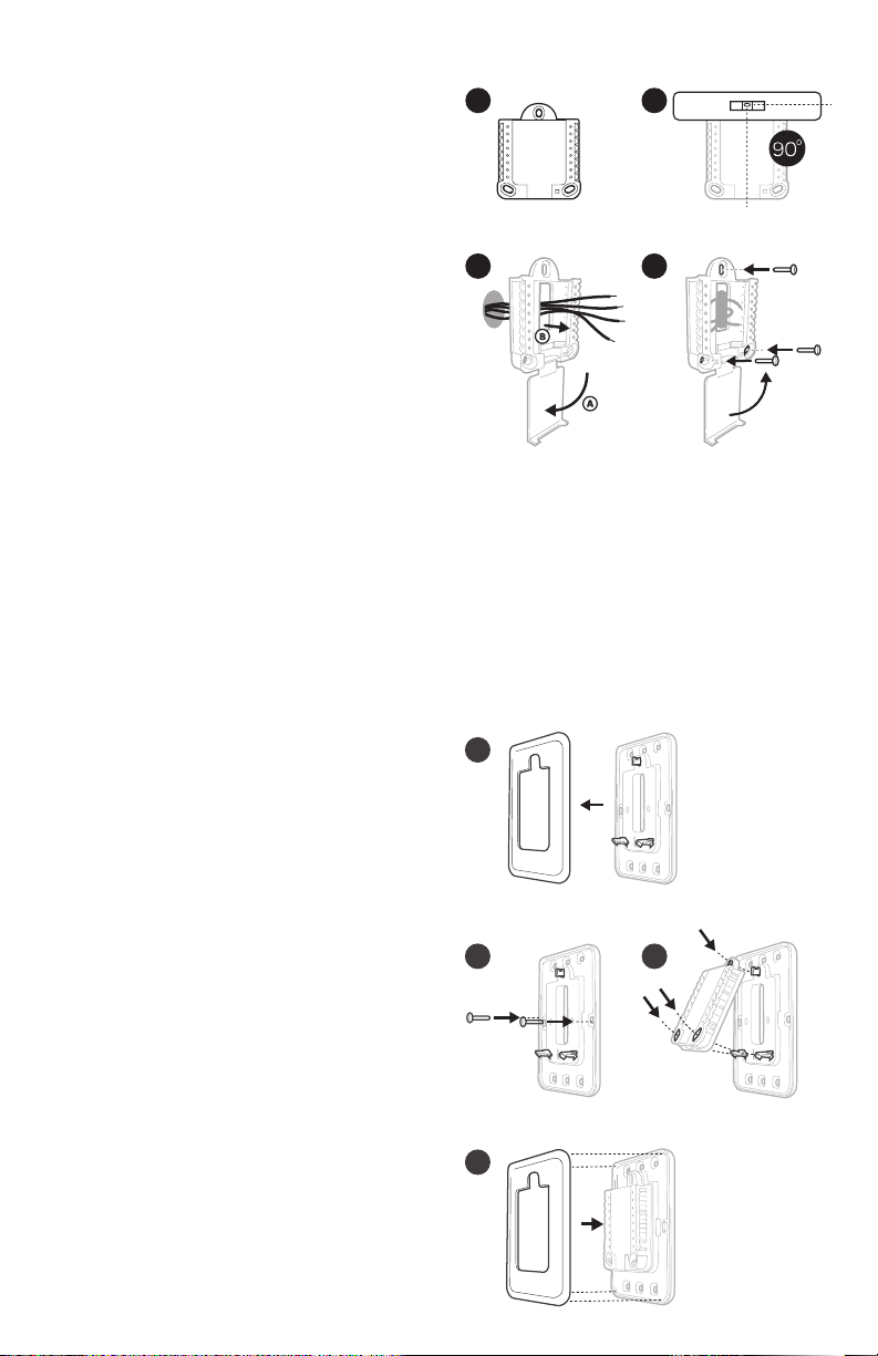
UWP Mounting System installation
1. Open package to find the UWP. See
1
Figure 1.
2. Position the UWP on the wall. Level and
mark hole positions. See Figure 2.
Drill holes at marked positions, and
then lightly tap supplied wall anchors
into wall using a hammer.
3
‒ If your box contains red anchors, drill
7/32” holes for drywall. If your box
contains yellow anchors, drill 3/16”
holes for drywall.
3. Pull the door open and insert wires
through wiring hole of the UWP. See
Figure 3.
4. Place the UWP over the wall anchors.
Insert and tighten mounting screws
supplied with the UWP. Do not
overtighten. Tighten until the UWP
no longer moves. Close the door. See
Figure 4.
Optional Decorative Cover Plate installation
2
4
Use 3x supplied
screws (#8 11/2
for red anchors and
#6 11/2 for yellow
anchors)
Use the Optional Cover Plate when:
• Mounting the thermostat to an
electrical junction box
• Or when you need to cover paint gap
from the old thermostat.
5. Separate the Junction Box Adapter
from the Cover Plate. See Figure 5.
6. Mount the Junction Box Adapter to
the wall or an electrical box using any
of the eight screw holes. Insert and
tighten mounting screws supplied with
Cover Plate Kit. Do not overtighten.
Make sure the Adapter Plate is level.
See Figure 6.
7. Attach the UWP by hanging it on the
top hook of the Junction Box Adapter
and then snapping the bottom of the
UWP in place. See Figure 7.
8. Snap the Cover Plate onto the
Junction Box Adapter. See Figure 8.
5
6
Use 2x
supplied
screws
#6 5/8”
(15.8 mm)
8
2
7
Page 3
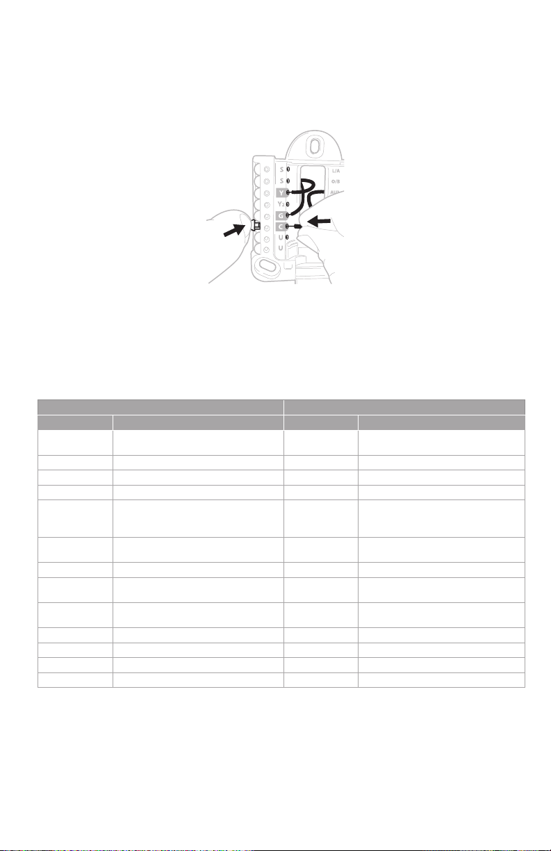
Wiring UWP
Push down on the tabs to put the wires into the inner holes of their corresponding termi nals
on the UWP (one wire per terminal) until they are firmly in place. Gently tug on the wires to
verify they are secure. If you need to release the wires again, push down the terminal tabs
on the sides of the UWP.
This wiring is just an example,
yours may vary.
Terminal designations
Conventional Systems Heat pump systems
Terminal Description Terminal Description
S/S
Y Compressor Stage 1 Y Compressor Stage 1
Y2 Compressor Stage 2 Y2 Compressor Stage 2
G Fan Relay G Fan Relay
C
K*
U/U** Relay for ventilation U/U** Relay for ventilation
A L/A
W Heat Stage 1 O/B
W2 Heat Stage 2 Aux Backup Heat
R 24 VAC Heating transformer R 24 VAC Heating transformer
Rc 24 VAC Cooling transformer Rc 24 VAC Cooling transformer
* The THP90 45A1098 C-wire adaptor is used on heat/cool systems when you only have four wires at
the thermostat and you need a fifth wire for a common wire. Use the K terminal in pl ace of the Y and
G terminals on conventional or heat pump systems to provide control of t he fan and the compressor
through a single wire—the unused wire t hen becomes your common wire . See THP90 45 instructions
for more information.
** Ventilation is not available on all models. When the U slider is in the dow n position (2 wires), the U
contacts are a dr y set of contac ts. If your ventil ation sy stem requires 24 volts, move the U slider to the
up position (1 wire). Lower U ter minal is internally jumped to the Rc terminal . In this application, you
would hook up one wire from your damper to the upper U terminal and the other to the common side of
the transformer.
Input for a wired indoor,
outdoor sensor
24VAC Common wire from
secondary side of cooling
transformer (if 2 transformers)
Connect to K on C-wire
adaptor
S/S
C
K*
E Emergency Heat
Input for a wired indoor,
outdoor sensor
24VAC Common wire from
secondary side of cooling
transformer
Connect to K on C-wire
adaptor
Connect to compressor
monitor
Changeover valve for heat
pumps
3
Page 4
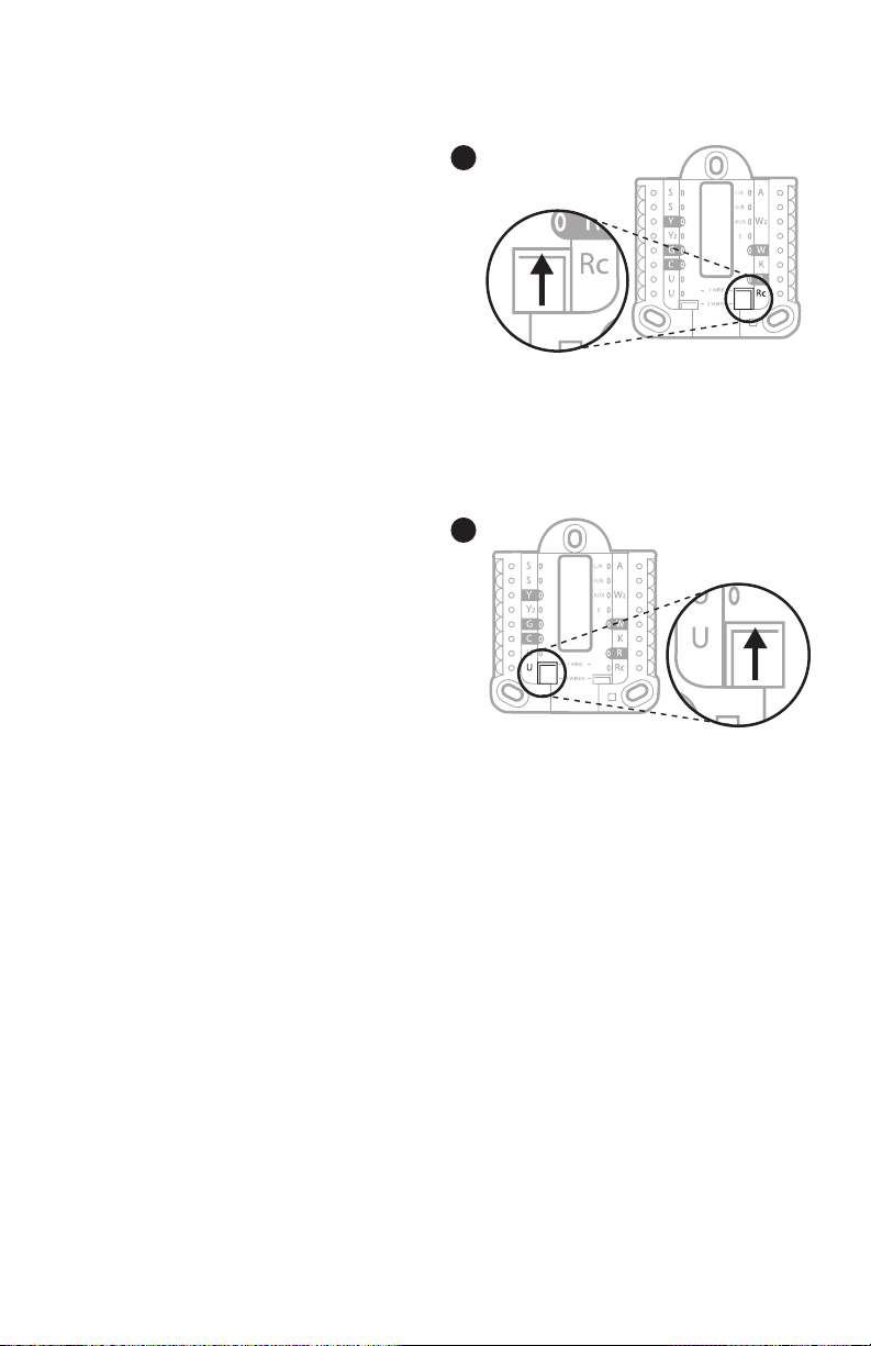
Setting Slider Tabs
Set R Slider Tab, see Figure 9.
• Use built-in jumper (R Slider Tab)
to differentiate bet ween one or two
transformer systems.
• If there is only one R wire, and it is
connected to the R, Rc, or RH terminal
on the old thermostat, set the slider to
the up position (1 wire).
• If there is one wire connected to the R
terminal and one wire connected to the
Rc terminal, set the slider to the down
position (2 wires).
Set U Slider Tab, see Figure 10.
• Use built-in jumper (U Slider Tab) of
relay to wire ventilation. Please note
that ventilation is not suppor ted on all
models.
• When the U Slider Tab is in the down
position (2 wires) the U contacts are a
dry set of contacts.
• If the ventilator is powered by the
cooling transformer, move the jumper
switch to the up position (1 wire). With
this switch set to 1 wire, the lower U
terminal is internally jumped to the Rc
terminal. In this application, hook up
one wire from the vent damper to the U
terminal and the other to the common
side of the cooling system transformer.
9
10
4
Page 5

Wiring
NOTES:
1 Available wiring configurations differ by product models/product numbers.
2 Use 18 to 22 gauge thermostat wire. Shielded cable is not required.
3 Set the R Slider Tab on the UWP to the up position (1 wire) for 1 transformer
systems or the down position (2 wires) for 2 transformer systems. See "Setting
Slider Tabs" on page 4.
4 Set the U Slider Tab to the up position (1 wire) for non-powered ventilation or the
down position (2 wires) for powered ventilation. See "Setting Slider Tabs" on page
4.
Conventional systems
1H/1C System (1 transformer)
R Power
Rc [R+Rc joined by Slider Tab]
Y Compressor contactor
C 24VAC common
W Heat relay
G Fan relay
Hot Water Relay Panel
R Power
Rc [R+Rc joined by Slider Tab]
W Heat Relay
C 24VAC common
NOTE: If the panel does not provide 24 volts AC
at R and C, set the slider to down position and
wire a separate transformer to Rc and C.
1H/1C System (2 transformers)
R Power (heating transformer)
Rc Power (cooling transformer)
Y Compressor contactor
C 24 VAC common from cooling transformer
W Heat relay
G Fan relay
2H/2C System (1 transformer)
R Power
Rc [R+Rc joined by Slider Tab]
Y Compressor contactor (stage 1)
C 24VAC common
W Heat relay (stage 1)
G Fan relay
W2 Heat relay (stage 2)
Y2 Compressor contactor (stage 2)
Heat-only System with Fan
R Power
Rc [R+Rc joined by Slider Tab]
C 24VAC common
W Heat relay
G Fan relay
Cool-only System with Fan
R Power
Rc [R+Rc joined by Slider Tab]
Y Compressor contactor
C 24VAC common
G Fan relay
5
Page 6

Heat pumps systems
1H/1C Heat Pump System
R Power
Rc [R+Rc joined by Slider Tab]
Y Compressor contactor
C 24VAC common
O/B Changeover valve
G Fan relay
2H/1C Heat Pump System
R Power
Rc [R+Rc joined by Slider Tab]
Y Compressor contactor
C 24VAC common
O/B Changeover valve
G Fan relay
Aux Auxiliary heat*
E Emergency heat relay*
L Heat pump fault input
NOTE: If dual fuel, TH6320WF2003
model needed.
2H/2C Heat Pump System
R Power
Rc [R+Rc joined by Slider Tab]
Y Compressor contactor (stage 1)
C 24VAC common
O/B Changeover valve
G Fan relay
Y2 Compressor contactor (stage 2)
L Heat pump fault input
3H/2C Heat Pump System
R Power
Rc [R+Rc joined by Slider Tab]
Y Compressor contactor (stage 1)
C 24VAC common
O/B Changeover valve
G Fan relay
Aux Auxiliary heat*
E Emergency heat relay*
Y2 Compressor contactor (stage 2)
L Heat pump fault input
NOTE: TH6320WF2003 only.
NOTE: Do NOT use W for heat pump applications. Auxiliary heat must wire to AUX or E.
* If you do not have separate wires for the Aux and E terminals, connect the wire to the Aux terminal.
6
Page 7

Ventilation systems
NOTE: Ventilation is not available on all models.
Using U Slider Tab
Wired to ERV/HRV whole
house ventilator with internal
power supply.
11 12
Mounting thermostat
Wired to fresh air damper
powered by furnace
transformer.
1 Push excess wire back into the wall
opening.
2 Close the UWP door. It should remain
closed without bulging.
3 Align the UWP with the thermostat, and
push gently until the thermostat snaps in
place.
4 If needed, gently pull to remove the
thermostat from the UWP.
5 Search for local rebates:
Your thermostat may now be eligible for
local rebates. Search for offers in your area
at HoneywellHome.com/Rebates
7
Page 8

Installer setup – using the thermostat
Setup using the thermostat
• After the thermostat has powered up,
touch START SETUP on the thermostat.
You’ll be asked if you want to perform
setup via app. Touch No.
• Touch
Installer Set Up (ISU) options.
• Touch Edit or touch text area, and
then touch
setup option.
• Touch Done or touch text area to
confirm the setting or press Cancel.
• Touch
another ISU option.
NOTES:
• To see a list of all setup parameters,
go to "Installer setup options (ISU) –
advanced menu" on page 11. The
thermostat displays the ISU name
and the ISU number.
• To finish setup and save your settings,
scroll to the Finish screen at the end of
the ISU list.
• Touch Select or touch text area to
save changes and exit, or touch
return to initial setup screen.
or to toggle between
or to edit default
or to continue to setup
to
option (scrolling)
ISU option blinking
Saves selected ISU
option moves on to
the next ISU screen
Done
View ISU
ISU #ISU name and
Edit
Edit ISU
ISU #
Cancel
No
Back
Arrow buttons used
to scroll through
ISUs
Arrow buttons used
to scroll through ISU
options
Cancels ISU option
selection, go back
to view ISU
Yes
Select
8
Page 9

Installer setup – using the Honeywell Home app
Setup using the app
Download the Honey well Home app from App Store or
Google Play to use a hidden PRO installation feature
that will allow you to configure the thermostat and
personally invite your customer to connect to the
installed thermostat at the same time.
Enter Contractor Mode
To enter Contractor Mode, press and hold the Honeywell Home logo for 5 seconds.
Then tap Confirm to begin using Contractor Mode. Follow steps to personally invite
your customer to connect their Honeywell Home App.
Installer setup – advanced menu
To access the advanced menu, press and hold the Menu button for 5 seconds.
Touch or to go through the options in the advanced menu.
Advanced menu options
Device Setup
This is used to access the device ISU setting.
Screen Lock
The thermostat touch screen can be set to lock
fully or partially.
Rater View
A read only place to view all the ventilation
settings.
System Test
Test the heating and cooling system.
Range Stop (Temperature)
Set the minimum, maximum, cool and heat
temperature set points.
9
Following Schedule
Mode
Heat
Wake Away Home Sleep
Reset
Access all reset options on the
thermostat. This is the only place
to access factory reset.
AM
Fan
Auto
Menu FanMode
Page 10

Key features
System status
information
Cool On, Heat On
Emergency Heat On,
Recovery, or Auto
Changeover On.
Schedule information
Following time-based
or location-based
temperature control.
Desired Temperature
Displays the current
desired temperature
setting.
Indoor Temperature
Displays the current
indoor temperature.
Mode
Select system mode:
Auto/Heat/Cool/Off/EM
Heat (Emergency Heat).
Time, ISU #, or
Alert #
AM
Heat On
Following Schedule
Mode
Heat
Wake Away Home Sleep
Recovery
Auto Chg. On
Fan
Auto
Menu Fa nMode
Menu
Touch to display
options. Start here
to set a program
schedule.
Note: Long press of
Menu button for 5
seconds to access
Advanced Menu
options.
Connection status
information
Status of WiFi
Connection: Connected,
Disconnected, or WiFi
is Off.
Messaging
Shows device setup
options, menu options,
reminders, schedule
overrides.
Schedule period
Shows schedule period:
Wake/Away/Home/
Sleep.
Fan
Select Fan mode Auto/
On/Circulate.
The screen will wake up by pressing the center area of the displayed temperature.
The screen will stay lit for 45 seconds. Brightness can be adjusted in the Menu.
10
Page 11

Installer setup options (ISU) – advanced menu
Tab le 1.
You can chan ge default MO FR, SA SU schedule h ere. To edit per iods during day s, temper ature setp oints, or to
turn Sc hedule On/ Off, from th e home scree n, go to MENU/SCHEDULE.
MOSU = E very day th e same
MOF R, SA, SU = 5 11 schedule
MO-FR, SA-SU = 5-2 schedule
# ISU ISU Name ISU Options (defaults in bold) Notes
120 Schedule Type No Schedule
Note: ISU options available may vary upon the thermostat model and equipment setup.
Honey well Home a pp and no wired o utdoor sens or is selec ted. We recom mend using a wir ed outdoor s ensor
conne cted to the “ S” terminal s on the UWP. (See " Wiring" o n page 5.)
An outd oor temper ature is requi red to set the f ollowing IS Us: ISU 355 C ompresso r Lockout , ISU 356 Aux
Heat Lo ckout, IS U 1013 Low O utdoor Temper ature Ventil ation Lockou t, ISU 1014 High Outd oor Temperatu re
Ventil ation Locko ut, and ISU 1015 High O utdoor Dew P oint Ventila tion Lockou t.
Basic s election o f system yo ur thermos tat will cont rol.
Each Da y = Every day in dividual
125 Tem p Sca le Fahrenheit, C elsius
130 Outdoor Temp No, Wired, Internet Sele ct outdoor te mperature d ata source . This ISU aut omaticall y defaults t o Internet wh en register ed to
Conventional Forced Air
200 Sys tem Ty pe
This op tion selec ts the equipm ent type yo ur thermos tat will con trol. Note : This optio n is NOT displaye d if ISU
200 is set t o Cool Only.
*Fan c oil setting i s for a reside ntial applic ation with a h ot water coil i n an air-handler.
Heat Pu mp
Boiler
Cool O nly
Standa rd Gas (STD G AS), High Ef ficiency Ga s (EFF GAS ),
Oil, E lectric , Fan Coil*
Heat Pump:
Air To Air, Ge othermal
205 Equipment Type Conventio nal Forced Air H eat:
on cool o r on heat
Boiler:
Hot Water, Steam
218 Reversing Valve 0/B on Cool, 0/B on He at This ISU is on ly displaye d if ISU 200 is se t to Heat Pump. S elect whe ther rever sing valve O/ B should ener gize
Maxim um of 2 Heat Stage s for conven tional sys tems. Max imum of 1 Aux/ E stages f or heat pump sy stems.
0, 1, 2 Only 1 co mpresso r stage avail able on TH6220W F model if con figured for h eat pump.
Heat St ages: 0, 1, 2
AUX /E Stage s: 0, 1
(#200 =Conv. /
200= HP)
Stages (#200=Conv./
220 Cool Stages
221 Heat Stages/Aux/E
only dis played if IS U 200 is set to He at Pump AND if IS U 221 Aux/E s tages = 1.
Note: T his ISU avail able on TH6320 mo del only.
200= HP)
230 Fan Control Equipment, Thermostat This I SU is only displ ayed if ISU 205 i s set to Elec tric Force d Air or Fan Coil .
253 Aux/E Control Both Aux/E, Either Aux/E Set “E ITHER AUX /E” if yo u want to setup a nd control A uxiliary a nd Emergenc y heating se parately . T his ISU is
11
Page 12

Installer setup options (ISU)– advanced menu
Tab le 2.
Note: O ptions of thi s ISU may var y depending on t he model of the t hermost at.
is set to r un AUX/ E heat separ ately.
Note: T his ISU may not b e available a t all on some mod els.
This I SU is display ed only if ISU 20 0 is set to Heat P ump AND if ISU 221 A ux/E he at stages = 1 , AND if ISU 256
is set to G as/Oil.
Note: T his ISU avail able on TH6320 mo del only.
indoor temperature.
ON (Automatic): On (enable d) Allows u ser to selec t Auto Change over as one of th e system mo des from
the hom e screen. In au to mode, the t hermost at can contr ol either he ating or cool ing to maintain t he desired
indoor temperature.
acti ve mode (heat o r cool) to the o pposite mod e when the the rmostat i s in auto-ch angeover. Dif ferentia l is
NOT dea dband. The de adband temp erature bet ween whe n heating (or coo ling) cycl es on and cycl es off to
mainta in setpoint i s not adjusta ble. The the rmostat u ses an algori thm that fix es deadban d at 0 °F (0 ° C).
higher s tage of the co oling equipm ent running unt il the desir ed setpoint i s reached.
keeps t he higher sta ge of the heati ng equipment r unning until th e desired se tpoint is re ached.
Aux he at droop can be s et on heat pump s ystems wi th an auxilia ry heat st age. The Com fort set ting is NOT
avail able for Dual Fu el system s. Default s etting is 0 ° F (0 ° C) (Comfort ) for Elect ric while 2 °F (1 .0 °C) for Gas /
Oil. T he indoor temp erature mu st drop to the se lected dro op setting b efore the th ermosta t will turn Aux H eat
on. For e xample, if A ux Heat is set t o 2 °F (1.0 °C), t he indoor temp erature mus t be 2 ° F (1.0 ° C) awa y from the
setp oint before Au x Heat turns o n. When set to C omfort , the thermo stat will u se Aux Heat as n eeded to kee p
the indo or temperat ure within 1 ° F (0.5 ° C) degree o f the setpoin t.
The Au xiliary He at Upstag e Timer star ts when th e highest st age of the prev ious heati ng equipment t ype turns
on. Au xiliary he at will be use d (if needed ) when the time r expires . This ISU is on ly displaye d when ISU 340 ( AUX
Heat Dr oop) is set to 2 °F (1 .0 °C) or highe r.
Heat)
# ISU ISU Name ISU Options (defaults in bold) Notes
255 Aux He at Type Electric, Gas /Oil (or Foss il Forced Ai r) This I SU is display ed only if ISU 20 0 is set to heat p ump AND if ISU 221 A ux/E he at stages = 1 .
256 EM Heat Ty pe Electric , Gas/ Oil (or Fossil F orced Air) This ISU i s displayed o nly if ISU 200 is s et to Heat Pump A ND if ISU 221 Au x/E heat s tages = 1 AND i f ISU 253
260 Fossil Kit Control Thermostat, E xternal ( Fossil Fue l Kit Contr ols Backup
300 Auto Changeover On, Off OFF: The us er must sele ct heating o r cooling as ne eded to maint ain the desir ed
303 Auto Differential 0 °F to 5 °F o r 0.0 °C to 2.5 ° C Diff erential is t he minimum numbe r of degrees r ise or fall re quired durin g off cycle t o switch fr om the last
Yes , No This ISU i s only displa yed when the t hermost at is set to 2 cool s tages. W hen set to YE S, this feat ure keeps th e
Yes , No This ISU i s only displa yed when the t hermost at is set to 2 or mor e heat stage s. When se t to YES, thi s feature
ments) o r 1.0 °C to 7.5 °C from s etpoint (in 0. 5 °C incremen ts)
Finish
Finish
305 High Cool St age
306 High Heat St age
340 Aux Heat Dro op 0 = Comfort ; 2 °F to 15 °F fr om setpoint ( in 1 °F incre-
Off, 30, 45, 60, 75, 90 min utes
2, 3, 4, 5, 6 , 8, 10, 12, 14, 16 hours
Heat
350 Up Stage T imer Aux
12
Page 13

Installer setup options (ISU)– advanced menu
Tab le 3.
Compr essor Lo ckout requir es an outdoo r temperatur e. Set Comp ressor Lo ckout to the te mperature b elow
which i t is ineffic ient to run the h eat pump. Whe n outside te mperature i s below this s etting, t hermosta t will
lockou t heat pump and r un Aux Heat onl y. This ISU is o nly display ed if ISU 130 = Wire d or Internet , ISU 200 is
set to He at Pump, ISU 221 A ux/E st ages = 1, AND I SU 260 is set to Th ermosta t. We recomm end using a wire d
remot e sensor as an ou tdoor tempe rature sour ce.
Defau lt is 40 °F (4.4 °C) if I SU 205 Heating E quipment is Ai r to Air Heat Pum p and ISU 255 Aux He at Type is
Gas/Oil .
Defau lt is Off if IS U 205 Heating Equ ipment is Air t o Air Heat Pump a nd ISU 255 Aux Hea t Type is Elect ric.
Defau lt is Off if IS U 205 Heating Equ ipment is Geo thermal .
Compr essor Lo ckout is optio nal for any ty pe of heat pump ( Air to Air Hea t Pump, Geot hermal Heat P ump).
Aux He at Lockout re quires an out door temper ature. Set A ux Heat Locko ut to optimize e nergy bill s and to not
allow i t to run the more e xpensive A ux Heat sour ce above cer tain outdo or temperat ure limit. T his ISU is onl y
displ ayed if ISU 200 i s set to Heat Pum p, AND ISU 260 is s et to Thermo stat cont rol AND if ISU 22 1 Aux/E
stage s = 1.
mum numbe r of times the s ystem can c ycle in a 1 hour pe riod measu red at a 50% loa d. For exampl e, when set
to 3 CPH, a t a 50% load, th e most the sy stem will c ycle is 3 time s per hour (10 minut es on, 10 minute s off).
The sy stem cycl es less of ten when lo ad condition s are less t han or greater t han a 50% load .
Off, 5 °F to 60 °F (in 5 ° F increment s) or
15.0 °C to 15.5 ° C (in 2.5 °C or 3.0 ° C increment s)
(Compressor Lockout)
# ISU ISU Name ISU Options (defaults in bold) Notes
355 Balance Point
Off, 5 °F to 65 °F (in 5 ° F increment s) or
15.0 °C to 18.5 ° C (in 2.5 °C or 3.0 ° C increment s)
1 - 6 CPH (3 CPH) This I SU is only displ ayed when C ool /Compre ssor Sta ges is set to 1 or m ore stage s. Cycle rat e limits the ma xi-
(Aux H eat Outdoo r
Lockout)
cycl e rate stage 1)
356 Aux Heat L ock Out
365 Cool 1 CP H (Cooling
number o f times the sy stem can c ycle in a 1 hour per iod measur ed at a 50% load. F or example , when set to
3 CPH, at a 5 0% load, the m ost the sy stem will cy cle is 3 times p er hour (10 minute s on, 10 minute s off). T he
sys tem cycles l ess ofte n when load co nditions ar e less than o r greater than a 5 0% load. Th e recommend ed
(default ) cycle rat e setting s are below for e ach heating e quipment t ype:
Standard Efficiency Gas Forced Air = 5 CPH; High Efficiency Gas Forced A ir =
3 CPH; Oil Forced A ir = 5 CPH; Electric Forced Air = 9 CPH; Fan Coil = 3 CPH; Hot
Water Radiant Heat = 3 CPH; Steam = 1 CPH.
are bel ow for each he ating equipme nt type:
Standard Efficiency Gas Forced Air = 5 CPH; High Efficiency Gas Forced A ir = 3
CPH; Oil Forced A ir = 5 CPH; Electric Forced Air = 9 CPH; Fan Coil = 3 CPH; Hot
Water Radiant Heat = 3 CPH; Steam = 1 CPH.
is conf igured. Th e recommend ed cycle ra te setting s are below for e ach heatin g equipment t ype:
Standard Efficiency Gas Forced Air = 5 CPH; High Efficiency Gas Forced A ir = 3
CPH; Oil Forced A ir = 5 CPH; Electric Forced Air = 9 CPH.
1 - 6 CPH (3 CPH) This I SU is only displ ayed when C ool /Compre ssor Sta ges is set to 2.
1 - 12 CPH This I SU is only displ ayed when H eat Stages i s set to 1 stage o r more stage s. Cycle ra te limits th e maximum
cycl e rate stage 2)
cycl e rate stage 1)
366 Cool 2 CPH (C ooling
370 Hea t 1 CPH (Heati ng
1 - 12 CPH This I SU is only displ ayed when H eat Stages i s set to 2 stage s. The rec ommended (def ault) cycl e rate sett ings
cycl e rate stage 2)
371 Heat 2 CP H (Heating
1 - 12 CPH This I SU is only displ ayed when I SU 200 = Heat Pump a nd ISU 221=1. It is only dis played whe n Auxiliar y Heat
(Heating cycle rate
Auxiliar y Heat)
375 Aux H eat CPH
13
Page 14

Installer setup options (ISU)– advanced menu
Tab le 4.
contr ol Aux and E hea t Independen tly. The rec ommended cy cle rate set tings are be low for each he ating equip -
ment type:
Standard Efficiency Gas Forced Air = 5 CPH; High Efficiency Gas Forced A ir =
3 CPH; Oil Forced A ir = 5 CPH; Electric Forced Air = 9 CPH.
rest arting to o early aft er a shutdown . The minimum- off timer i s activat ed after the c ompress or turns of f. If
there i s a call during t he minimum- off timer, the t hermost at shows “ Wait” in the di splay. This I SU is display ed if
ISU 220 is s et to at least 1 s tage.
Afte r the call for c ooling end s, the therm ostat keep s the fan on for t he selecte d amount of time f or increas ed
eff iciency. Thi s may reintro duce humidit y into the liv ing space. T his ISU is dis played if IS U 220 is set to at lea st
1 stage.
Afte r the call for h eating ends , the therm ostat keep s the fan on for t he selecte d amount of time f or increase d
eff iciency. Thi s ISU is displ ayed if ISU 230 is s et to Therm ostat Con trols Fan.
ensur ing the indoor t emperatur e will match th e setpoint at t he schedule d time.
1 - 12 CPH This I SU is only displ ayed when E mergency He at is config ured and ISU 253: A ux/E Termin al Control is s et to
(Heating cycle rate
# ISU ISU Name ISU Options (defaults in bold) Notes
378 EM He at CPH
Off, 1 - 5 minutes The th ermostat h as a built in comp ressor pr otection (m inimum off tim er) that preve nts the compr essor fr om
Emergency Heat)
387 Compres sor
Off, 30, 60, 90 sec onds
2, 3, 4, 5, 6 , 7, 8, 9, 10, 11, 12, 13 , 14, 15 minut es
Off, 30, 60, 90 sec onds
2, 3, 4, 5, 6 , 7, 8, 9, 10, 11, 12, 13 , 14, 15 minut es
Protection
in Cool
in Heat
390 Ext F an Run Time
391 Ex t Fan Run Tim e
425 Adaptive Recovery On, Off Adapt ive Intelli gent Recove ry (AIR ) is a comfor t setting . Heating or co oling equipm ent will turn o n earlier,
429 Max Cool Temperature from Min . Cool Temp. to 99 ° F or to 37.0 °C (90 °F or 32 °C) The user c annot set the c ooling temp erature abo ve this leve l.
430 Min Cool Temperature from 50 ° F or 10.0 °C to Max . Cool Temp. (5 0 °F or 10 °C ) T he user canno t set the cool ing tempera ture below t his level.
page 5. T his ISU is onl y displayed o nly if ISU 130 is se t to NO wired ou tdoor senso r configure d
ISU 500 .
sourc e to be used or yo u can ask ther mostat to us e both therm ostat and re mote senso rs for higher ac curacy of
measurement.
Choose either calendar or equipment run time-based reminder.
Off
431 Max He at Temperatur e from Min. He at Temp. to 90 °F or to 32 .0 °C (90 ° F or 32 °C) The use r cannot set t he heating te mperature a bove this lev el.
432 Min Heat Temperature from 40 °F or 4.4 ° C to Max. Hea t Temp. (50 °F or 10 °C) The us er cannot set t he heating te mperature b elow this le vel.
500 Indoor Sensor Yes , No Set this I SU when you wa nt to wire a remo te indoor sen sor to the “S ” terminals o n the UWP - see " Wiring" o n
515 Sensor type 10k, 20 k Choo se resist ance type o f wired indoo r sensor. This I SU is only dis played whe n indoor sens or is configu red -
520 Temperature Control Ther mostat, W ired, Average This ISU i s only displ ayed when ind oor sensor is c onfigured - I SU 500. You can ch oose what te mperature
702 Air Filte rs 0 - 2 This I SU refers to t he number of air f ilters in the s ystem.
711 Air Filter 1 Reminder
Choose either calendar or equipment run time-based reminder.
10, 20, 30, 45, 60, 9 0, 120, 150 Run Time D ays
30, 45, 60, 75 Day s
3, 4, 5, 6, 9, 12 , 15 Months
Off
10, 20, 30, 45, 60, 9 0, 120, 150 Run Time D ays
30, 45, 60, 75 Day s
3, 4, 5, 6, 9, 12 , 15 Months
712 Air Filter 2 Reminder
14
Page 15

Installer setup options (ISU)– advanced menu
Tab le 5.
ERV/HRV: The thermostat controls an Energy Recovery Ventilator or Heat Recovery Ventilator for ventila-
tion.
Passive (Fan Only): The ther mostat tu rns on the fan fo r ventilat ion. When se t to passiv e fan, the the rmo-
stat do es not cont rol a damper or ve ntilator. Th e passive v entilatio n/passiv e fan sett ing only runs th e indoor
blowe r fan. This se tting doe s not open a damp er or run a venti lator. To use this s etting for v entilatio n, the home
would n eed to be set-up w ith a pipe fro m outdoors i nto the retur n duct that is ei ther perma nently open o r has a
damper t hat automati cally open s whenever t he blower fa n is on.
Note: S ome models o nly offer th e passive f an settin g.
Equipment: Ventilation equipment controls the blower fan.
Off
6, 12 Cal endar Month s
Off
30, 60 Ca lendar Days
3 - 12 Cale ndar Months (i n 1 month increm ents)
Reminder
# ISU ISU Name ISU Options (defaults in bold) Notes
810 Hum Pad Reminder
921 Dehum Filter
1000 Vent Type None, ER V/HRV, Pass ive, Fresh A ir Damper None: The thermostat does not control ventilation.
1005 Vent Method ASHR AE 2010, ASHR AE 2013, Perc ent On Time N ote: Option s of this ISU ma y vary depe nding on the mod el of the therm ostat.
1006 Vent Fan Control Thermostat, Equipment Thermostat: T he thermos tat turns on t he ventilat ion and the fan w hen ventil ation is need ed.
1007 Bedroom s 1 - 6 (2) This I SU is only displ ayed when I SU 1005 Ventila tion Method i s set to ASHR AE 2010 or 2013.
1008 Home Size 1000 S q. Ft. - 5000 S q. Ft. (10 00 Sq . Ft.) This ISU i s only displa yed when ISU 10 05 Ventilatio n Method is se t to ASHR AE 2010 or 2013.
1012). For ex ample, if Per cent on Time i s set to 50%, t he ventilat ion equipmen t will run at ran dom times dur-
ing a 1 hour p eriod until i t reaches a 50 % run time (appr oximately 30 mi nutes). Thi s ISU is only dis played if
ISU 1005 is s et to Percen t On Time.
stand ard. The the rmostat w ill not run ven tilation dur ing the foll owing lockou t conditio ns (if configu red), unle ss
you manually call for ventilation:
Locko ut Ventilati on during Outd oor Condit ions (ISU 1013, 1014 and 1015).
Locko ut Ventilati on during “Sl eep” progra m periods. N ote: This opt ion is set by th e user on the Vent ilation
scree n in the Menu.
ASHRAE is Priority: A SHRAE re quires addi tional venti lation fol lowing a long of f cycle. T he thermo stat
meet s the ASHR AE ventil ation stand ard by running a dditional ve ntilation w hen outdoor c onditions a re favor-
able. I f ASHRA E cannot be met w hen outdoo r condition s are favorab le, the ther mostat wi ll override t he outdoor
lockou ts and run ven tilation . When using th is option, it i s recommen ded that you inc rease the r ate (CFM) of
the ven tilation eq uipment to mee t the ASHR AE ventil ation stan dard in a short er run time. T he ability t o lockout
ventil ation durin g the “Sleep ” is not an option w hen you sele ct ASHR AE is Priori ty.
1009 Vent Rate 30CFM - 3 50CFM (in 5CF M increment s) (150CFM) Thi s ISU is only di splayed wh en ISU 1005 Ventil ation Meth od is set to AS HRAE 2010 or 2013.
1011 Vent Percent On Time 10% - 100% (30%) The th ermostat o perates ve ntilation e quipment ba sed on a perce ntage enter ed in the inst aller setup ( ISU
1012 Vent Priority Lockouts, ASHR AE Lockouts are Priority: The t hermost at places a p riority o n lockouts ve rsus the A SHRAE ve ntilation
15
Page 16

Installer setup options (ISU)– advanced menu
Tab le 6.
ISU 130 mu st be set to Wir ed or Interne t. This ISU i s only displ ayed when IS U 1000 Ventilat ion Type is set to
ERV / HR V or Fresh Ai r Damper.
ISU 130 mu st be set to Wir ed or Interne t. This ISU i s only displ ayed when IS U 1000 Ventilat ion Type is set to
ERV / HR V or Fresh Ai r Damper.
ISU 130 mu st be set to Inte rnet. Thi s ISU is only di splayed if I SU 1000 Ventila tion Type is set t o ERV/ HRV or
Fres h Air Damper.
Off, 20 °F to 40 °F (in 5 ° F increment s) or
28.0 °C to 4.0 ° C (in 2.0 °C incr ements)
Off, 80 °F to 110 °F (in 5 ° F increment s) or
26 °C to 44 ° C (in 2 °C increme nts)
Off, 65 °F to 85 °F (in 5 ° F increment s) or
18 °C to 30 °C (i n 2 °C incremen ts)
Vent Loc kout
Vent Loc kout
Dewpoint Vent
Lockout
# ISU ISU Name ISU Options (defaults in bold) Notes
1013 Low Ou tdoor Temp
1014 High Out door Temp
1015 High Outdoor
remind er can be setu p for each one se parately.
1017 Vent Core Reminder Off, 3, 6, 9, 12 m onths This I SU is display ed only if ISU 10 00 is set to ERV/ HRV.
1018 Vent Filter Reminder Off, 3, 6, 9, 12 m onths
1100 UV De vices 0 - 2 S ome syste ms may have tw o UV device s, one for th e ACoil and an other for Air Tre atment. A r eplaceme nt
1105 UV Bu lb 1 Reminder Off, 6 , 12, 24 months
brightness).
1106 UV Bu lb 2 Reminder Off, 6 , 12, 24 months
1401 Idle Brightness 0 = Off, 0 - 5 Adjus t brightne ss of an inacti ve backlig ht (idle scree n) from defau lt 0 (backlig ht off) to 5 (ma ximum
0 °F (0 °C) - N o differen ce in display ed temperat ure and the ac tual room temp erature. T he thermos tat can
displ ay up to 3 °F (1.5 C) l ower or higher t han the actua l measured t emperatur e.
1.5 °C to 1.5 ° C (in 0.5 °C incr ements)
1410 Clock Format 12 hour, 24 hour
1415 Daylight Saving On, Off Set t o Off in area s that do not fol low Dayligh t Saving Tim e.
1420 Temp Off set Off, 3 °F to 3 °F (in 1 °F in crements) or
16
Page 17

Performing a system test
You can test the system setup in ADVANCED
MENU under SYSTEM TEST option.
1 Press and hold Menu on the thermostat for
5 seconds to access ADVANCED MENU
options.
2 Touch
3 Touch Select or touch text area.
4 Touch
Touch Select or touch text area.
5 For the heat test and cool test, use
to activate each stage of the equipment.
For the fan test, use
on and off.
NOTE: The clock is used as a timer while the
stages are running. The Heat On and Cool On
indicators are displayed when the system test
is running.
or to go to SYSTEM TEST.
or to select system test type.
or to turn the fan
or
Back Select
Back Select
Heat On
Heat
Done
Viewing equipment status
You can see the status of thermostatcontrolled equipment in the Menu under the
EQM T STATUS option.
1 Touch Menu on your thermostat.
2 Touch
Touch Select or touch text area.
3 Touch
equipment the thermostat is controlling.
Depending on what feature the thermostat
supports or how it was installed, the
Equipment Status screen reports data for
the following systems:
• Heating and cooling
• Fan
• Ventilation (available on certain
or to go to EQMT STATUS.
or to view statuses of all the
models only)
17
Back Select
Done
Page 18

Troubleshooting
Screen is blank • Check circuit breaker and reset if necessary.
• Make sure power switch at heating and cooling system is on.
• Make sure furnace door is closed securely.
Screen is difficult
to read
• Change screen brightness in thermostat Menu. Increase brightness intensity for
inactive backlight of the thermostat screen (max. is level 5).
Heating or
cooling system
does not respond
• Touch Mode to set system to Heat. Make sure the temperature is set higher than
the Inside temperature.
• Touch Mode to set system to Cool. Make sure the temperature is set lower than
the Inside temperature.
• Check circuit breaker and reset if necessary.
• Make sure power switch at heating & cooling system is on.
• Make sure furnace door is closed securely.
Heat runs with
cooling
• Verify there is not a wire attached to W for heat pump systems. See wiring on
pages 56.
Alerts and reminders
Alerts and reminders are displayed via the alert symbol and alert number in the clock
area on the home screen. You can read more information about active alerts, snooze
or dismiss non-critical alerts in Menu/Alerts.
Number Alert/Reminder Definition
164 Heat Pump Needs
Service
168 WiFi Radio Error Wireless features are not available. Try removing the
170 Internal Memor y Error The memory of the thermostat has encountered an
171 Set the Date and Time Set the date and time on your thermostat . The date and
173 Thermostat
Temperature Sensor
Error
175 AC Power Resumed AC power resumed to thermostat after power loss.
177 Indoor Temperature
Sensor Error
178 Outdoor Temperature
Sensor Error
Heat pump needs service. Contact dealer to diagnose
and service heat pump.
thermostat from the wallplate or power cycle at breaker
for 1 minute. If the code is still shown, please contact
dealer to replace the thermostat.
error. Please contact dealer for assistance.
time are required for certain features to operate, like the
program schedule.
The sensor of the thermostat has encountered an error.
Please contact dealer to replace the Thermostat.
Wired indoor temperature sensor is not connected
or there is a wiring shor t. Please contact dealer for
assistance.
Wired outdoor temperature sensor is not connected
or there is a wiring shor t. Please contact dealer for
assistance.
18
Page 19

Alerts and reminders
Number Alert/Reminder Definition
181 Replace Air Filter (1) Replace air filter (1). Reset the timer by touching
182 Replace Air Filter (2) Replace air filter (2). Reset the timer by touching
183 Clean Humidifier Tank
and Replace Water
Filter
184 Replace Humidifier
Pad
185 Replace Dehumidifier
Filter
186 Clean Ventilator Core Clean ventilator core. Reset the timer by touching
187 Clean or Replace
Ventilator Filter
188 Replace UV Bulb (1) Replace UV Bulb (1). Reset the timer by touching
189 Replace UV Bulb (2) Replace UV Bulb (2). Reset the timer by touching
210 Register Online For
Outdoor Temperature
388 Register Online for
Remote Access and
Outdoor Temperature
399 No Internet The connection to the Internet has been lost. Please
400 No WiFi Signal The WiFi signal has been lost. Please wait for the
508 WiFi Not Configured Please download the Honey well Home app and follow
the "dismiss" button on thermostat screen after it is
replaced.
the "dismiss" button on thermostat screen after it is
replaced.
Clean humidifier tank and replace the water filter, or
contact dealer to do this for you. Reset the timer by
touching the “dismiss” button on the thermostat screen
after it is replaced.
Replace humidifier pad. Reset the timer by touching
the “dismiss” button on the thermostat screen after it is
replaced.
Replace the dehumidifier filter. Reset the timer by
touching "dismiss" but ton on thermostat screen after it
is replaced.
the “dismiss” button on thermostat screen after it is
replaced.
Clean or replace ventilator filter. Reset the timer by
touching the “dismiss” button on thermostat screen
after it is replaced.
the "dismiss" button on thermostat screen after it is
replaced.
the "dismiss" button on thermostat screen after it is
replaced.
Online registration is required to receive outdoor
temperature from the Internet. Outdoor temperature
is needed for your current system setup. Download the
Honey well Home app to register your thermostat .
Online registration is required for remote access and
outdoor temperature. Download the Honeywell Home
app to register your thermostat.
check your network settings.
thermostat to reconnect or select a new WiFi network.
Follow steps in the Honeywell Home app
the steps to connect thermostat to your WiFi network .
19
Page 20

CAUTION: ELECTRIC AL HAZARD
Can cause electrical shock or equipment damage. Disconnect power before beginning installation.
CAU TION: EQUIPME NT DAMA GE HAZARD
Compressor protection is bypassed during testing. To prevent equipment damage, avoid cycling the compressor
quickly.
CAUTION: MERCURY NOTICE
If this product is replacing a control that contains mercury in a sealed tube, do not place the old control in the trash.
Contact your local waste management authority for instructions regarding recycling and proper disposal.
Specifications
Temperature Ranges
Heat: 40 °F to 90 °F (4.5 °C to 32.0 °C)
Cool: 50 °F to 99 °F (10.0 °C to 37.0 °C)
Operating Ambient Temperature
37 °F to 102 °F (2.8 °C to 38.9 °C)
Shipping Temperature
20 °F to 120 °F (28.9 °C to 48.9 °C)
Operating Relative Humidity
5% to 90% (non-condensing)
Electrical Ratings
Terminal Voltage
W Heating 20 Vac30 Vac 0.02 A1.0 A
(Powerpile) 750 mV DC 100 mA DC
W2 (Aux) Heating 20 Vac30 Vac 0.02 A1.0 A
E Emergency Heat 20 Vac30 Vac 0.02 A0.5 A
Y Compressor Stage 1 20 Vac30 Vac 0.02 A1.0 A
Y2 Compressor Stage 2 20 Vac30 Vac 0.02 A1.0 A
G Fan 20 Vac30 Vac 0.02 A0.5 A
O/B Changeover 20 Vac30 Vac 0.02 A0.5 A
L/A Input 20 Vac30 Vac 0.02 A0.5 A
U 20 Vac30 Vac 0.02 A0.5 A
Power Consumption
Backlight On: 1.48VA
Backlight Off: 0.88VA
(50Hz/6 0Hz)
Running
Current
Physic al Dimension s in inches ( mm) (H x W x D)
T6 Pro Smart Thermostat (TH6320WF2003):
45/64 x 45/64 x 11/16 (104 x 104 x 27)
T6 Pro Smart Thermostat (TH6220WF2006):
45/64 x 45/64 x 11/16 (104 x 104 x 27)
UWP Mounting System (included):
29/32 x 213/64 x 243/64 (58 x 56 x 10)
Standard Installation Adapter (THP2400A1076):
329/32 x 357/64 x 21/32 (99 x 99 x 17)
Decorative Cover Plate – Small (included):
449/64 x 449/64 x 11/32 (121 x 121 x 9)
Decorative Cover Plate – Large (THP2400A1068):
67/64 x 67/64 x 9/32 (155 x 155 x 7)
5-year limited warranty
For Warranty information go to
http://customer.resideo.com
Regulatory information
FCC RE GULATIO NS
47 CFR § 15.1 9 (a)(3)
This device complies with part 15 of the FCC Rules. Operation is subject to the
following two conditions:
1. This device may not cause harmful interference, and
2. This device must accept any interference received, including interference
that may cause undesired operation.
47 CFR § 15.2 1 (USA only)
Changes or modifications not expressly approved by the party responsible for
compliance could void the user’s authority to operate the equipment.
47 CFR § 15 .105 (b)
See https://customer.resideo.com/enUS/support/residential/codesand-standards/F CC15105/Pages/default.aspx for additional FCC
information for this product.
Resi deo Inc., 1 985 Dougla s Drive Nor th
Golde n Valley, MN 55 422
www.resideo.com 33-00392—07 M.S. Rev. 10-19 | Printed in United States
This product is manufactured by Resideo Technologies, Inc., Golden Valley, MN, 1-800-468-1502
©2019 Resideo Technologies, Inc. The Honeywell Home trademark is used under license from Honeywell
International Inc. All rights reserved.
IC REGULATIONS
RSS-GEN
This device contains licence-exempt transmitter(s)/receiver(s) that comply
with Innovation, Science and Economic Development Canada’s licence-exempt
RSS(s). Operation is subject to the following two conditions:
1. This device may not cause interference.
2. This device must accept any interference, including interference that may
cause undesired operation of the device.
The operation of this equipment is subject to the following two conditions:
(1) this equipment or device may not cause harmful interference, and (2) this
equipment or device must accept any interference, including interference that
may cause undesired operation.
Wi-Fi® is a registered trademark of
Wi-Fi Alliance®
 Loading...