

Page 1
HONEYWELL SECURITY TECHNICAL BULLETIN 11 December 2008
Honeywell Video Systems
Subject: Control HNDR-S 4848 DVR by VideoBlox HEGS5BLX
Introduction
This document describes the Protocol Interface Translator (PIT) operation specific to the Honeywell HNDR-S
series DVR. For further details on the PIT, please refer to the PIT User manual. For further details on the DVR,
please refer to the appropriate Honeywell HNDR-S DVR manual.
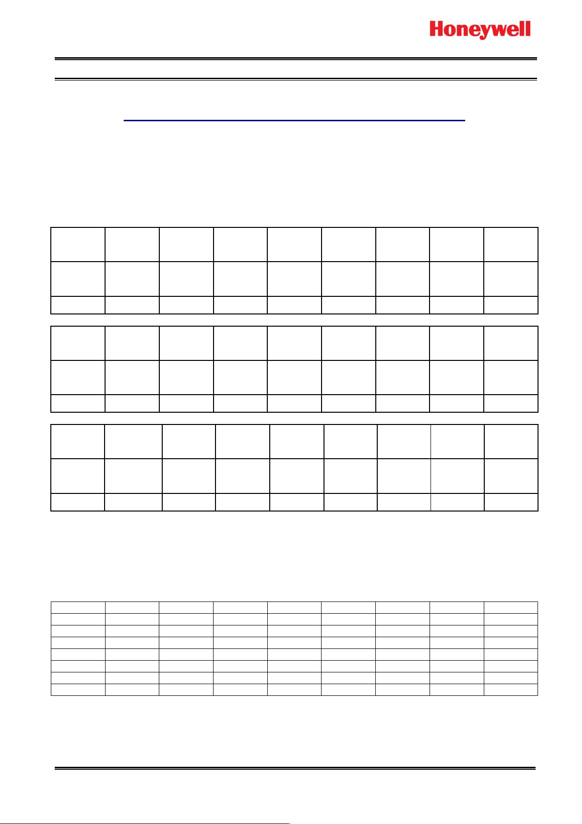
Quick Start Switch Settings
Output
Protocol
Off Off Off Off On On On On
Address S2/8 S2/7 S2/6 S2/5 S2/4 S2/3 S2/2 S2/1
Switch
Legend
0 (B/cast) Off Off Off Off Off Off Off Off
Input
Protocol
Bossware On Off On Off On On On Off
The above setting set the PIT as follows:
Receive Betatech compatible Bossware control messages on the RS422 slave port of the PIT at 19.2K baud.
The PIT unit address (S2/1 - S2/8 to OFF position) is set to broadcast, so all addresses will be translated. If
want to control specific unit of DVR, set the dip switch S2/1 – S2/8 of PIT address and add PIT per DVR. (It is
tested the address from 1 to 128.)
Unit ID S2/8 S2/7 S2/6 S2/5 S2/4 S2/3 S2/2 S2/1
1 Off Off Off Off Off Off Off On
2 Off Off Off Off Off Off On Off
3 Off Off Off Off Off Off On On
4 Off Off Off Off Off On Off Off
5 Off Off Off Off Off On Off On
:
255 On On On On On On On On
Transmit Honeywell HNDR-S control messages on the RS422 master port at 9600 baud, 8, N, 1 .
Note: To control HNDR-S series DVR, the DVR firmware should be 1.0.17 or later.
(Tested firmware: HVBCPUX – 4.96x HVBCFG – 3.08 (Build 32) HVBPIT44 – 3.03)
www.asia.security.honeywell.com Rev 1.0 1 of 5
S1/8 S1/7 S1/6 S1/5 S1/4 S1/3 S1/2 S1/1
Valid
Function
Address 7 Address 6 Address 5 Address 4 Address 3 Address 2 Address 1 Address
S3/8 S3/7 S3/6 S3/5 S3/4 S3/3 S3/2 S3/1
Slave Port
Baud
Valid
Function
Slave
Port
Baud
Valid
Function
Master
Port Baud
Valid
Function
Master
Port Baud
ASCII
string
mode
Input
Type
ASCII
string
mode
Input
Type
ASCII
string
mode
Input
Type
ASCII
string
mode
0
Input
Type
Page 2
HONEYWELL SECURITY TECHNICAL BULLETIN 11 December 2008
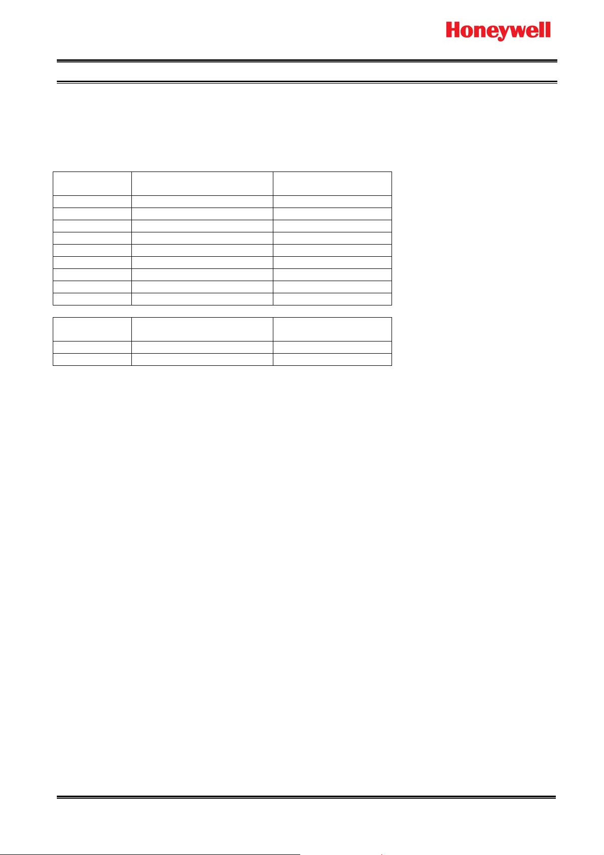
Hardware Configuration
• Connect CPU RS422 Master Port to Slave Port of HVBPIT44.
• Connect Master Port of HVBPIT44 to HNDR-S Com 2 (RS-485).
Pin Number
1 Tx- Rx2 Tx+ Rx+
3 Rx+ Tx+
4 Rx- Tx5 Signal Gnd Signal Gnd
6 +12V source +12V input
7 NC NC
8 NC NC
9 Ground Ground
Pin Number
1 Tx- Tx
2 Tx+ Rx
CPU RS422 Master Port
(DB9 Female)
HVBPIT44 Master Port
(DB9 Female)
HVBPIT44 Slave Port
(DB9 Female)
HRHD-S Com 2
www.asia.security.honeywell.com Rev 1.0 2 of 5
Page 3

HONEYWELL SECURITY TECHNICAL BULLETIN 11 December 2008
Device Configuration
Go to Control page to configure external CCTV peripherals which may be controlled by VideoBloX keyboard.
1. Copy the HNDR-S.db and HNDR-S.mb files to root directory “C:\Program
Files\Honeywell\VBloXCFG\DBF\”
2. Execute the VbloxCFG software and go to “Control” page.
3. Select the “Device Type” which is to be configured.
4. Click
5. Set “Com Port” to “1” if the control signal to the device is connected to the VideoBloX CPU master
communications port.
6. Set the “Control Type” to the type of interface used to control the external device.
7. Set “Switch Offset” to “-1” if no automatic video switch operation is required when the device is selected.
The offset will be added to the selected device number and the resulting value will be used as the matrix
video input channel which will be selected. e.g. Switch Offset =29, the first channel of HNDR-S DVR is
input 30.
8. Click “Download” button to download after changed.
icon to browse “HNDR-S.db” which is locate in “C:\Program Files\Honeywell\VBloXCFG\DBF\”
www.asia.security.honeywell.com Rev 1.0 3 of 5
Page 4

HONEYWELL SECURITY TECHNICAL BULLETIN 11 December 2008
HNDR-S 4848 DVR Configuration
1. Configure Communication port
a. Push Menu button of DVR and enter the DVR setting menu.
b. Move to System menu and select Serial Setup.
c. Move to COM2 485 and select Keyboard HTX-3000 as below figure.
2. Configure Keyboard Control Address and Keyboard PTZ address as below figure.
a. Push Menu button of DVR and enter the DVR setting menu.
b. Move to Miscellaneous menu.
c. Select Keyboard Control Address to 1.
www.asia.security.honeywell.com Rev 1.0 4 of 5
Page 5

HONEYWELL SECURITY TECHNICAL BULLETIN 11 December 2008
HEGS5BLX Operation
To select “HNDR-S 4848”, press “DVR” button. Then press “1” + “Enter” b uttons to select DVR number 1.
Joystick
KJIML
A B C D E F G H
DVR Function Keys
Item Function supported
by Keyboard
1 Menu Press “H”
2 Play Press “B”
3 Rewind Press “G”
4 Forward AUX Mode LED on, Press “C”
5 Search Press “C”
6 Sequence Press “F”
7 Select AUX Mode LED on, Press “E”
8 Multi-screen AUX Mode LED on, Press “F”
9 Exit AUX Mode LED on, Press “G”
10 Enter AUX Mode LED on, Press “H”
11 Up Hold down “ALT” + “Up”
12 Down Hold down “ALT” + “Down”
13 Left Hold down “ALT” + “Left”
14 Right Hold down “ALT” + Right”
15 DVR channel select
* Detail DVR operation procedure, please refer to the DVR manual.
Note: The information contained herein is subject to change without notice.
Description
(The Keyboard should be in DVR mode for the below operation)
I: Use to move between menu items
J: Select DVR channel depending on the position
K: Select DVR channel depending on the position
L: Select DVR channel depending on the position
M: Use to move between menu items
www.asia.security.honeywell.com Rev 1.0 5 of 5
 Loading...