

Honeywell GX-Series, GX-520, GX-48 Installation And Setup Manual

GX-Series Control Panel Installation and Setup Guide
GX-Series Control Panel
Installation and Setup Guide
800-05928 9/10 Rev. B


GX-Series Control Panel Installation and Setup Guide
Table of Contents
INTRODUCTION.....................................................................................................................................................1-1
Variants ..................................................................................................................................................................1-1
Terminology Glossary .............................................................................................................................................1-1
SECTION 1: QUICK SET UP ..................................................................................................................................1-2
SECTION 2: SYSTEM ARCHT ECT URE ...............................................................................................................2-1
Mounting the Control Cabinet .................................................................................................................................2-2
Installing the Cabinet Lock......................................................................................................................................2-2
Installing the PCB in the Control .............................................................................................................................2-3
RS485 Expansion Module (GX -520 onl y) .......................................................................................... ....................2-5
Transformer Installation Instructions.......................................................................................................................2-5
Connecting the Control Unit to Earth Ground .........................................................................................................2-6
Power Requirements...............................................................................................................................................2-6
Connecting the GX-Series to the PSTN..................................................................................................................2-7
Line Monitoring .......................................................................................................................................................2-7
Stand-by Battery .....................................................................................................................................................2-7
Battery Start-up ......................................................................................................................................................2-8
Memory ...................................................................................................................................................................2-8
RS485 Data Communication Bus (AB Lines)......................................................................................................... 2-9
RS485 Wiring Configurations .................................................................................................................................2-9
RS485 Wiring Recommendations ..........................................................................................................................2-9
Zones ....................................................................................................................................................................2-11
Zone Addresses ................................................................................................................ ...................................2-11
Zone Addressing with On-board RIO Switc h (Line 0 Switc h) ..............................................................................2-11
Wiring Zones ........................................................................................................................................................2-12
Wiring Multiple Detectors. .....................................................................................................................................2-13
Wiring Keyswitches ..............................................................................................................................................2-14
Wiring Terminator Buttons ....................................................................................................................................2-14
Outputs .................................................................................................................................................................2-14
Output Applications ..............................................................................................................................................2-15
Trigger Header .....................................................................................................................................................2-15
Trig 1-6 .................................................................................................................................................................2-15
Supply .................................................................................................................................................................. 2-16
SPI Header ...........................................................................................................................................................2-16
SECTION 3: PERIPHERALS .................................................................................................................................3-1
General....................................................................................................................................................................3-1
Wiring .....................................................................................................................................................................3-1
Configuring .............................................................................................................................................................3-1
Addressing ..............................................................................................................................................................3-1
Connecting the RIO.................................................................................................................................................3-1
Configuring the RIO.................................................................................................................................................3-2
RIO Zones...............................................................................................................................................................3-2
RIO Outputs ............................................................................................................................................................3-2
Ethernet Module......................................................................................................................................................3-2
Configuring the Ethernet Module ............................................................................................................................3-3
Ethernet Communication.........................................................................................................
ote Servicing Suite...........................................................................................................................................3-3
Rem
SECTION 4: KEYPADS ..........................................................................................................................................4-1
The GX-Series Mk7 Keypad....................................................................................................................................4-1
General....................................................................................................................................................................4-1
Power Consumption................................................................................................................................................4-1
Wiring the Keypad...................................................................................................................................................4-1
................................3-3
i

GX-Series Control Panel Installation and Setup Guide
Addressing...............................................................................................................................................................4-1
Keypad Installation Procedure ................................................................................................................................4-1
Volume Control........................................................................................................................................................4-3
Adding a Keypad to the System..............................................................................................................................4-3
Removing a Keypad from the System.....................................................................................................................4-3
Self Diagnostics.......................................................................................................................................................4-3
Keypad/ Operation ..................................................................................................................................................4-4
Multiple Group S ystems .........................................................................................................................................4-5
Power LED ..............................................................................................................................................................4-5
Display ....................................................................................................................................................................4-5
The GX-Series TouchCenter...................................................................................................................................4-6
General ...................................................................................................................................................................4-6
TouchCenter Installation Procedure .......................................................................................................................4-6
Configuring a TouchCenter ....................................................................................................................................4-6
Set-up Menu ...........................................................................................................................................................4-7
TouchCenter - Operatio n ........................................................................................................................................4-7
Specifications .........................................................................................................................................................4-7
SECTION 5: ACCESS CONTROL .........................................................................................................................5-1
Group Based Access Control .................................................................................................................................5-1
User and Access Templates ..................................................................................................................................5-1
Time Schedules ......................................................................................................................................................5-1
Door Control Module ..............................................................................................................................................5-1
Inputs.......................................................................................................................................................................5-3
Connecting a Wiegand Device................................................................................................................................5-3
Wiegand Reader Inputs...........................................................................................................................................5-3
Buzzer Output .........................................................................................................................................................5-3
LED Output..............................................................................................................................................................5-4
Relay Output............................................................................................................................................................5-4
Installation and Mounting ........................................................................................................................................5-4
Mounting the RIO Box.............................................................................................................................................5-4
Wiring the Reader to the DCM................................................................................................................................5-4
Addressing with DIP Switches.................................................................................................................................5-4
Connecting the DCM to GX-Series System ............................................................................................................5-4
Configuring the DCM...............................................................................................................................................5-4
Specifications ..........................................................................................................................................................5-5
SECTION 6: SYSTEM OPERATION .....................................................................................................................6-1
Menu Options..........................................................................................................................................................6-1
General ...................................................................................................................................................................6-1
The Full Menu .........................................................................................................................................................6-1
The Quick Menu .....................................................................................................................................................6-1
Menu Access ..........................................................................................................................................................6-2
Engineer (Installer) Mode .......................................................................................................................................6-2
Setting (Arming) Options ........................................................................................................................................6-4
Setting (Arming) the System Using a PIN ..............................................................................................................6-4
Cancelling the Setting (Arming)................................................................................................
etting (Disarming) the System Using a PIN ......................................................................................................6-5
Uns
...............................6-4
Engineer Unsetting (Installer Disarming) ................................................................................................................6-5
Keyswitch Setting (Arming) Options .......................................................................................................................6-5
Setting (Arming) the System with Proximity Cards .................................................................................................6-5
Cancelling and Resetting Alarms and Alerts ..........................................................................................................6-6
Recording of Events ...............................................................................................................................................6-6
Overriding of Faults and Tampers...........................................................................................................................6-6
Setting (Arming) Features ......................................................................................................................................6-7
Menu Options ......................................................................................................................................................6-10
ii

GX-Series Control Panel Installation and Setup Guide
Option 11 – Omit (Bypass) Zones [Quick Menu Option 0] ...................................................................................6-10
Option 12 – Timed Set (Arm) ...............................................................................................................................6-11
Option 13 – Part Set (Part Arm)............................................................................................................................6-11
Option 14 – Forced set (Forced bypass) [Quick Menu Option 1] .........................................................................6-11
Option 15 – Chime [Quick Menu Option 2] ..........................................................................................................6-11
Option 16 – Instant Set (Instant Arm)....................................................................................................................6-11
Option 17 – Silent Part .........................................................................................................................................6-11
Option 18 – Home Set (Arm) [Stay] ......................................................................................................................6-12
Option 19 – All Set (Arm) [Away] ..........................................................................................................................6-12
Option 21 – Display Zones [Quick Menu Option 3] ..............................................................................................6-13
Option 22 – Display Log [Quick Menu Option 4] ..................................................................................................6-13
Option 23 – System...............................................................................................................................................6-14
Option 24 – Print [Quick Menu Option 5] .............................................................................................................6-14
Option 25 – Access Doors ....................................................................................................................................6-15
Option 31 – Walk Test [Quick Menu Option 6] .....................................................................................................6-18
Option 32 – Outputs .............................................................................................................................................6-19
Option 41 – Time/Date [Quick Menu Option 7] ....................................................................................................6-20
Option 42 – Codes [Quick Menu Option 8] ..........................................................................................................6-20
Option 43 – Dlight Saving [Quick Menu Option 9] ...............................................................................................6-28
Option 44 – Trace .................................................................................................................................................6-28
Option 45 – Timer Control ....................................................................................................................................6-28
Option 46 – Group omit (Area bypass) ................................................................................................................6-32
Option 47 – Remote Access ................................................................................................................................6-33
Option 48 – Engineer (Installer) access ...............................................................................................................6-38
Engineer 1 ...........................................................................................................................................................6-39
Option 51 – Parameters........................................................................................................................................6-39
Option 52 – Program Zones .................................................................................................................................6-53
Option 53 – Program Outputs ..............................................................................................................................6-65
Option 54 – Links .................................................................................................................................................6-79
Option 55 – Soak ..................................................................................................................................................6-82
Option 56 – Communications ...............................................................................................................................6-83
Option 57 – System Print ...................................................................................................................................6-105
Option 58 – Keypad ............................................................................................................................................6-106
Option 59 – Quick Menu .....................................................................................................................................6-109
Engineer 2 .........................................................................................................................................................6-110
Option 61 – Diagnostics ......................................................................................................................................6-110
Option 62 – Full Test ..........................................................................................................................................6-113
Option 63 – Options ...........................................................................................................................................6-114
Option 64 – Assemble Zone ...............................................................................................................................6-117
Option 65 – Timers .............................................................................................................................................6-120
Option 66 – Pre-check s ......................................................................................................................................6-125
Option 67 – Remote Reset .................................................................................................................................6-126
Option 68 – Menu Access ..................................................................................................................................6-126
Option 69 – Integrated Access Control .........................................................................................
ngineer 3 .........................................................................................................................................................6-133
E
.....................6-127
Option 71 – SPI Key ...........................................................................................................................................6-133
Appendix A: Library ............................................................................................................................................... A-1
Appendix B: SIA and Contact ID Event Codes ..................................................................................................... B-1
Appendix C: SIA Event Structure .......................................................................................................................... C-1
Appendix D: Event Log Messages ........................................................................................................................ D-1
Appendix F: Specific ations .................................................................................................................................... E-1
Appendix F: Parts List Index ...................................................................................................................................F-1
Appendix G: Regulatory Agency Statements.........................................................................................................G-1
iii

GX-Series Control Panel Installation and Setup Guide
iv

GX-Series Control Panel Installation and Setup Guide
INTRODUCTION
This manual gives full instructions required to install and program a GX-Series control panel and associated
peripherals.
The GX-Series provides the following features:
Features GX-48 GX-520
Zones 16-48 16-520
Outputs (400mA) 8-24 8-24 8-260
Trigger Outputs on Flying Lead (100mA) 6 6
Power Supply Unit (PSU) 2.5A 2.5A
RS485 Databuses 1 4
Telecom onboard Yes Yes
RS232 Interface for online PC RS232 RS232
Printer Interface RS232 RS232
Ethernet option Yes Yes
Groups 8 32
Keypads 8 32
Multi-user Yes Yes
Door Control Modules (DCM's) with 2 x wiegand
interfaces
DCM Controlled doors 8 64
Access control groups (user templa tes) 50 100
Weekly Timer Schedules 19 67
Annual Holiday Schedules 16 32
Users 100 999
Links (Outputs) 64 256
Remote software update Yes Yes
Upload/Download Yes Yes
Remote service Yes Yes
Network downloader Yes Yes
Alarm monitoring Yes Yes
Graphics mimic Yes Yes
TouchCenter 1 4
Mimic panel Yes Yes
SMS (Short Message Service / Texting) Yes Yes
4 32
Table 1-1. GX-Series General Information
TERMINOLOGY GLOSSARY
Term Meaning Term Meaning
DCM Door Control Module RIO Remote Input Output
Module
Engineer Security System Installer Set / Setting Arm(ed) / Arming
ent
esc
PA Personal/Panic Attack
Prox Reader Proximity card reader
Prox tag Proximity card
Enter key Unset / Unsetting Disarm(ed) / Disarming
Escape key User Type User (Authority) Level
1-1

GX-Series Control Panel Installation and Setup Guide
SECTION 1: QUICK SETUP
To quickly set arm up a GX-Series control panel for programming follow these simple steps:
1. Connect a 1k • resistor across each of the zones on the panel and any RIO’s (if connected).
2. Ensure that the tamper return loop — the terminals marked as AUX TAMP/GND on the PCB — is a
complete loop.
3. Connect a keypad to the AB LINE terminals on the control panel.
Control Panel
(Line 1)
B1 B
A1 A
- -
+12V +
Table 1-2. Terminal Connections
4. Connect a 680 • End Of Line (EOL) resistor across the A and B terminals of the keypad.
5. Ensure that the keypad is installed on the wall (see Keypad Installation Procedure, Section 4).
6. Connect the battery.
7. Connect the AC wiring to the control panel.
8. Switch on the AC power and remove the protective cover from the PCB battery.
9. The following sequence of events occur:
• the keypad buzzer and control panel horn (if installed) activate for 10 - 20 seconds,
• flashing *************** is displayed on the keypad,
• the sounders stop and the keypad displays become blank,
• the green power LED lights and the following displays on the keypad
Configuring
Please Wait
• the default banner is then displayed on the keypad.
GX <XXX> <VY. YY >
01:01 SUN 01 JAN
where: XXX is the panel type
Y.YY is the panel software revision
Keypad
10. The system is now ready to be programmed. Refer to Section 6 System Operation for programming
details.
11. Default User code is 12345
Default Engineer (Installer) code is 112233
1-2
GX-Series Control Panel Installation and Setup Guide
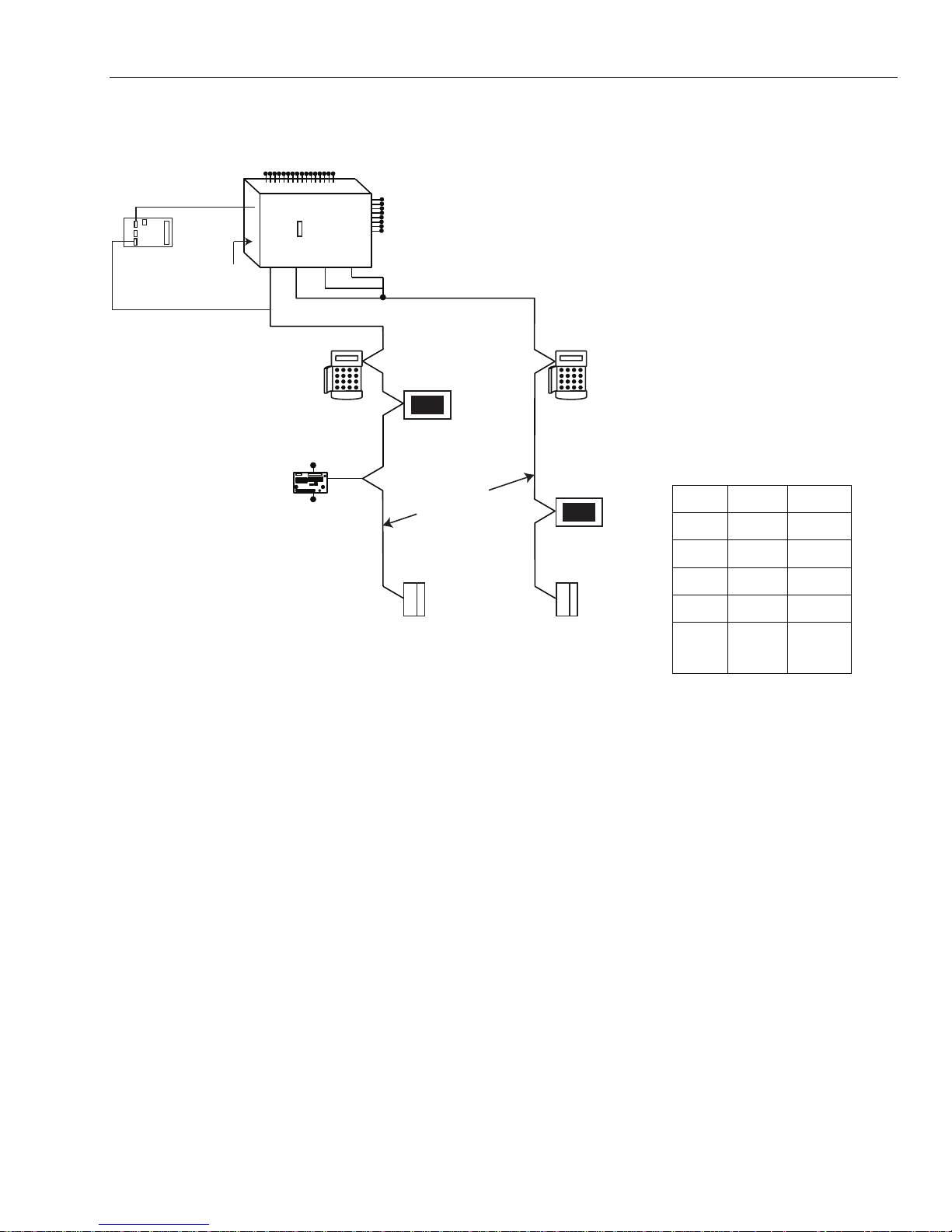
SECTION 2: SYSTEM ARCHITECTURE
16 zones on board
PSTN (comm 1)
Audio Interface
‡
Module (1)
RS485 line
‡ Not Evaluated by UL.
*
NOTE:
Valid addresses for the
keyprox are:
Line 1 (0, 1 & 2).
Line 2 (0, 1, 2, & 3 ).
This sets the address for both
the keypad and card reader
parts of the keyprox.
*
Certain keypad and
max addresses can
be replaced by a
combined keyprox unit.
NOTE:
The Ethernet module can only be
connected to line 1.
If an Ethernet module is attached,
keypad address B cannot be
connected to line 1 (address B is
shown as 15 on the system).
RS232
Serial Port
(comm 6)
GX Series
on board
telecom
Trigger
area
Header
Line
Line
12
RIO
C072
Line Line
CABLE RUN 1 KM (MAX)
*
K
eypad
Mk 7
4 outputs
8 zones
8 outputs
on board
plus 6 outputs
on trigger header
4
3
Lines 2, 3 and 4 have
the same configuration
*
Keypads
Touch
Center
CP041
Mk 7
Twisted Pair
Screened Cable
DCM
C080/81
DCM
C080/81
Touch
Center
CP041
GX-001-V4
GX-48 GX-520
Lines
Keypa
ds
Touch
Center
DCM's
RIO's
1 4
8 8 per line
1 1 per line
4 8 per line
4
15 (line
1)
6 (lines
2, 3, 4)
Figure 2-1. GX-Series System Configuration
2-1
GX-Series Control Panel Installation and Setup Guide
Mounting the Control Cabinet
To mount the control cabinet, perform the following steps:
Do not attempt to remove the knockouts after the circuit board has been installed
Step Action
1. Before mounting the circuit board, remove the metal knockouts for the wiring entry that you will
be using.
2. Using fasteners or anchors (not supplied), mount the control cabinet to a sturdy wall in a clean,
dry area that is not readily accessible to the general public. The back of the cabinet has 4 holes for
this purpose.
To provide certificated burglary service for UL installations, refer to the special requirements and
U
L
Figure 2-3. Cabinet Attack Resistance Considerations to follow.
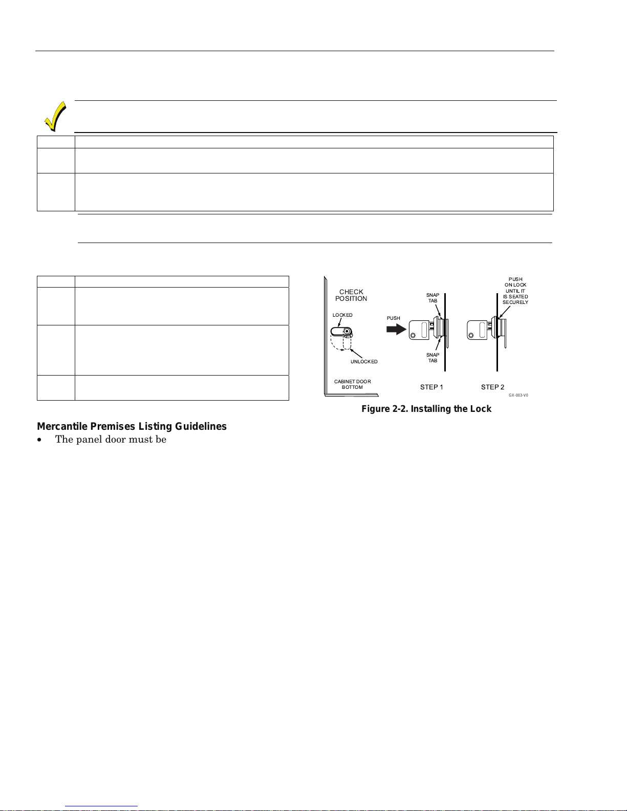
Installing the Cabinet Lock
To install the lock, see Figure 2-2 and perform the following steps:
Step Action
1. Remove cabinet door, then remove the
lock knockout from the door. Insert the
key into the lock.
2. Position the lock in the hole, making
certain that the latch will make contact
with the latch bracket when the door is
closed.
3. When correctly positioned, push the lock
until it is held securely by its snap tabs.
Figure 2-2. Installing the Lock
GX-003-V0
Mercantile Premises Listing Guidelines
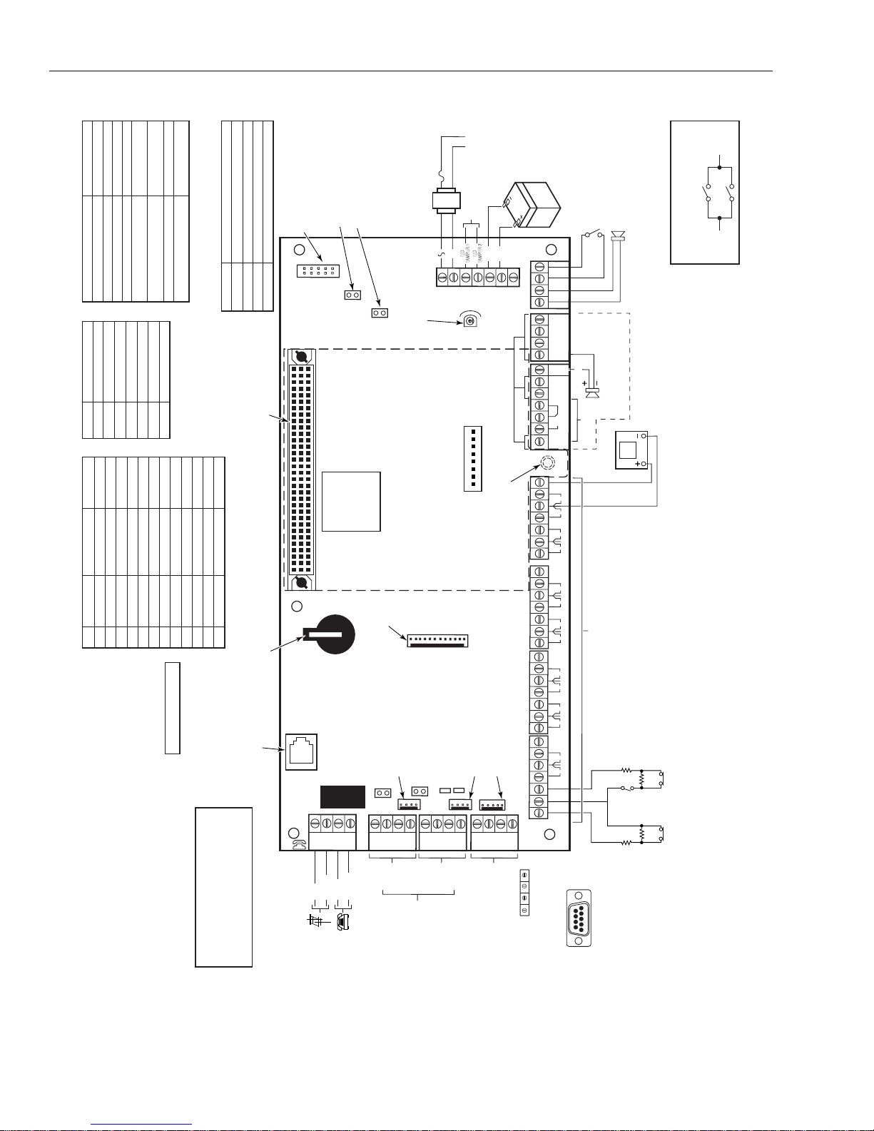
• The panel door must be supervised. Mount the clip-on tamper switch (supplied) to the cabinet's right
side wall and wire it to the cover tamper on the PCB. See Figure 2-4 for the location of the PCB terminal
block.
• All wiring between the transformer and panel must be run in conduit. Remaining wires do not need to be
run in conduit.
• All unused knockouts must be plugged using the disc plugs and carriage bolts (supplied), as indicated in
Figure 2-3.
• Fasten the cabinet door to the cabinet backbox using the 15 one-inch-long Phillips-head screws
(supplied) after all wiring, programming, and checkout procedures have been completed.
2-2

GX-Series Control Panel Installation and Setup Guide
MOUNTING
SCREWS
(3)
PLUG THIS
KNOCKOUT
TAMPER
SWITCH
LOCATION
ONON
F1
4455
2233
66
11
7788
B3
A4
B4
A3
C
N/C
N/O
CABINET
TAMPER
SWITCH
LOCATION
PLUG THIS
KNOCKOUT
RUN ALL REMAINING
WIRE THROUGH HERE
TO PLUG AN UNUSED KNOCKOUT OPENING,
REMOVE KNOCKOUT AND INSTALL A PAIR OF
DISC PLUGS AND A CARRIAGE BOLT AS SHOWN.
KNOCKOUT
OPENING
HEX NUT AND
WASHER
DISC PLUGS
(DIMPLES IN DISC
PLUG SHOULD
REGISTER INSIDE
KNOCKOUT OPENING)
CARRIAGE BOLT
CABINET SIDE WALL
(OUTSIDE)
GX-102-V1
TRANSFORMER
AND LOCKWASHER
CABINET DOOR
RUN BELL WIRES
IN CONDUIT
WIRES MUST BE
RUN IN CONDUIT
GND WIRE (GRN)
NUT (GRN)
PC
BOARD
PLATE
MOUNTING
SCREWS
(3)
PLUG THESE
KNOCKOUTS
Figure 2-3. Cabinet Attack Resistance Considerations
Mercantile Safe and Vault Listing Guidelines
• Follow the guidelines given above for Mercantile Premises listing.
• For safe and vault installations, a shock sensor (not supplied) that is listed for protection of sheet metal
enclosures, as well as an additional tamper switch, must be installed on the cabinet backbox to protect
the cabinet from being removed from the wall. These devices must also be wired to the cover tamper on
the PCB. See Figure 2-4 for the location of the PCB terminal block.
Installing the PCB in the Control
To install the circuit board in the cabinet, perform the following steps:
Step Action
1. Confirm the Mounting Plate is installed securely in the cabinet.
2. Place the board flat and secure to the mounting plate with the six accompanying screws. (See
Figure 2-3)
NOTE: Make sure that the mounting screws are tight.
Use shielded wire or keep wiring away from the microprocessor (center) section of the PC board. Use the
mounting plate brackets on the left and right sidewalls of the cabinet for anchoring field wiring using tie
wraps (Figure 2-3). These steps are important to minimize the risk of panel RF interference with television
reception.
The 7 transistorized outputs on the GX-Series can be configured to open collectors by setting the dip switch
SW3 to the OFF position. Table 2-1 shows which outputs are controlled by which switches.
Note: Output 2 on RIO 0 (relay output) is not affected. This is a f orm C r ela y that can switch up t o 1 amp at
24 volts DC.
(SW3) RIO Output
1 0 1
2 0 3
3 0 4
4 1 1
5 1 2
6 1 3
7 1 4
Table 2-1. SW3 Transistorized Output Control
2-3
GX-Series Control Panel Installation and Setup Guide
BLACK
Poor Communication
Normal Communication
TABLE 3 - COMMUNICATION STATUS
LED (LED 1) STATE INDICATION
Single pulse at end of call Normal Communication
On - 01s, Off- 0.9s Normal Communication
LED Off No DC supply
9W-D SIGNAL NAME
PIN 7 CTS
PIN 8 RTS
PIN 5 GROUND
TABLE 2 - RS232 CONNECTIONS
‡
On during alarm monitoring,
Remote Servicing and SMS
Flashing at end of alarm call Failed Communication
PIN 2 Tx
PIN 3 Rx
Flashes in time with ringing signal Line Ringing
Pulses as each digit is dialed Normal indication when
Flickering during alarm monitoring,
Remote servicing and SMS
PIN 6 SHORT TO PIN 4
PIN 4 SHORT TO PIN 6
TABLE 1 - TRIGGER HEAD
TRIGGER 2 00028 100 mA
TRIGGER 3 00037 100 mA
TRIGGER 4 00046 100 mA
TRIGGER 5 00055 100 mA
TRIGGER 6 00064 100 mA
NOT USED N/A3 N/A
CONNECTION OUTPUT ADDRESS MAX. OUTPUTPIN
NOT USED N/A2 N/A
+12V N/A 100 mA1
IC: 573F-GXSERIES
RS485 DATA BUS LINES MUST USE DAISY CHAIN WIRING BETWEEN MODULES.NOTE 1:
RESISTOR ACROSS THE A&B WIRES. IF THE PANEL DOES NOT FORM ONE END
OF THE BUS, REMOVE THE LINK TO DISABLE THE 680 OHM RESISTOR.
NOTE 3: WIRING METHOD SHALL BE IN ACCORDANCE WITH THE NATIONAL ELECTRICAL CODE
NOTE 2: EACH END OF THE RS485 DATA BUS MUST BE TERMINATED WITH A 680 OHM
CONNECTIONS.
QUICK INSTALLATION INSTRUCTIONS (P/N 800-05372 REV A)
INSTALLATION INSTRUCTIONS (P/N 800-05928 REV A)
[ANSI/NFPA70], LOCAL CODES, AND THE AUTHORITIES HAVING JURISDICTION.
‡ NOT EVALUATED BY UL.
NOTE 5: FOR UL INSTALLATIONS, 26AWG CABLE (MINIMUM) IS REQUIRED FOR TELECO
NOTE 4: FOR MORE INFORMATION, REFER TO THE FOLLOWING DOCUMENTS:
making a call
The on-board Telecom Module monitors the PSTN line
under normal idle state conditions. LED 1 indicates the
communications status.
LED STATE INDICATION
LED 2 Flashes Ethernet Module sending or receiving data
LED 2 OFF No Communication on RS232 line
LED 2 ON Communication between Control Panel and PC
LED 1 ON Ethernet Module connected to Ethernet
STATUS
TABLE 4 -
ETHERNET
COMMUNICATION
2XRS485
INTERFACE
EXPANSION CARD
2. Replace with good battery.
3. Reconnect mains supply.
4. Reconnect 12V battery.
0V GND N/A12 N/A
NOT USED N/A11 N/A
NOT USED N/A10 N/A
TRIGGER 1 00019 100 mA
Memory backup battery replacement:
1. Remove memory backup
battery with a small flat
head screwdriver.
BACKUP
BATTERY
MEMORY
BACKUP LITHIUM
BATTERIES ARE TO
WARNING: TO PREVENT RISK
‡
BE REPLACED BY
PERSONNEL ONLY.
TRAINED SERVICE
ALTERNATE PHONE
RJ11 CONNECTORS
LINE CONNECTION FOR
OF SHOCK DISCONNECT
TELEPHONE LINES AT TELCO
JACK BEFORE SERVICING
THIS UNIT.
SPI
HEADER
PROGRAM
LINE
B
RING
RED
INCOMING
JUMPER MUST BE INSTALLED
MICRO
PHONE
A
B
A
TIP
TIP
RING
GREY
GREEN
BROWN
LINE
PREMISES
TELEPHONE
TELEPHONE
DO NOT PLACE JUMPER
OVER 2 PINS.
DEVELOPMENT PURPOSE ONLY
LK2
TAMPER
OFF WALL
PROCESSOR
B1
(NOTE 5)
POWER LIMITED
ALL CIRCUITS ARE
STARTUP
BATTERY
(SEE TABLE 1)
TRIGGER HEAD
LK3 RS485 LINE 2, 680 Ω TERMINATION
(NOTE 2)
A1
RS485
LINE 1
DATA BU S
CONNECTION
2A
AND THE BATTERY.
1451 TRANSFORMER
EXCEPT THE OUTPUT OF
MODEL 1451
TRANSFORMER
BLUE
LK4
HORN OUTPUT
LOUD SPEAKER
VOLUME CONTROL
ONLY
RS-485
GX-520
MODULE
EXPANSION
1
ENGINEER SOCKET
(RS485 LINE 1)
LK5 RS485 LINE 1, 680 Ω TERMINATION
(NOTE 2)
+12V
GND
A2
B2
RS485
(NOTE 1)
MODULES
(LINE 1 ONLY)
(MK7 KEYPAD
RIO EXPANDER,
TOUCHCENTER,
FOR PERIPHERAL
ETHERNET MODULE
1.0A MAX
120VAC, 60 Hz
CONNECT TO
INPUT RATING
WHITE
SEE DETAIL
BELOW
BLUE
LID
LID
AC
-BAT
TAMPER 1
TAMPER 2
RIO
SWITCH
78
2 34561
ON
SW 3
PULL-UP (DIP) SWITCHES
12
* FOR TB1 - TB4: USE
RS232 PORT SOCKET
ENGINEER SOCKET
(RS485 LINE 2)
LED 1 (FOR TELECOMS)
LED 2 (FOR TELECOMS)
+12V
RX
TX
GND
LINE 2
RS232
(NOTE 1)
CONNECTION
MODULE)
DOOR CONTROL
CIRCUIT
A DEDICATED
CAPACITY IS
FOR UL
EMERGENCY
LEAST 4 HOURS
REQUIRED FOR
STANDBY FOR AT
12V 7AH BATTERY
+BAT
2341
N/C
N/C
SWITCHED 0V OUTPUTS
2 341
N/0
** TB5 ** TB6
RS485 EXPANSION
MODULE STANDOFF
+12V
+12V
EOL RESISTOR (1KOHM)
P/N 300-02343 SUPPLIED
IN SAP0166 PACKAGE
FOR UL INSTALLATIONS.
+12V
FOR CABLE A234
* TB1 * TB2 * TB3 * TB4
CTS
RTS
RTS
CTS
COM PORT
RX
TO PC SERIAL
TX
PANEL TERMINALS
INSTALLATIONS
TWO 12V 7AH BATTERIES
RIO 1RIO 0
+12V
+12V
8
0V0V
7
6
5
RIO 1
4
0V
3
2
0V
1
8
0V
7
6
0V
5
RIO 0
4
0V
3
2
0V
1
ARE REQUIRED
TAMPER SWITCH
FOR EXAMPLE
ON EXTERNAL
SIREN
GND
AUX T AMP
AUX 3
12V POWERED LOAD. EG: SIREN,
RELAY
OUTPUT
POWERED
16 ON-BOARD ZONES
(FEMALE)
CONNECTOR
9-WAY D-TYPE
NOTE: MAINTAIN
1/4" SEPARATION
OF POWER LIMITED
AND NON-POWER
LIMITED CIRCUITS
LOUND
SPEAKER
8-32Ω
NOTE: MAXIMUM LOAD
FOR LOUD SPEAKER IS
100 mA DC WITH SPEAKER
IMPEDANCE OF 8Ω
WARNING LAMP, ELECTRONIC
LOCK, ETC. FOR ALL SWITCHED
0V OUTPUTS
DETECTOR
**NOTE: FOR TB5 AND TB6: TOTAL MAXIMUM CURRENT
DRAW FOR THE SWITCHED AUX OUTPUTS = 400mA.
OR
ZONES 1-8 (RIO 0 LINE 1)
ZONES 1-8 (RIO 1 LINE 0
SWITCH 3-8 ON)
ZONES 1-8 (RIO 1 LINE 1
SWITCH SW3-8 OFF)
* NOTES: FOR TB1 - TB4: USE
EOL RESISTOR (1KOHM)
P/N 300-02343 SUPPLIED
IN SAP0166 PACKAGE FOR
UL INSTALLATIONS;
TOTAL MAXIMUM CURRENT
DRAW FOR THE +12V AUX
OUTPUTS = 1A.
1 K Ω
1 K Ω
ALARM
CONTACT
SWITCH
TAMPER
(OPTIONAL)
1 K Ω
ALARM
CONTACT
1 K Ω
(SEE TABLE 2)
LID
TAMPER
2
DETAIL
(CONNECT AS SHOWN)
DOOR AND REAR TAMPER
1
LID
TAMPER
GX SERIES
(TYPICAL)
ZONE WIRING
(FOR ALL ZONE PAIRS)
UL Applications: Proprietary,
Commercial Central Station,
Local Mercantile Burglar Alarm,
Access Control Unit, Standard
Line Security, Dual Line
Transmission via PSDN and
DACT
GX-SOC-V4
SUMMARY OF CONNECTIONS
Figure 2-4. PCB Layout
2-4
GX-Series Control Panel Installation and Setup Guide
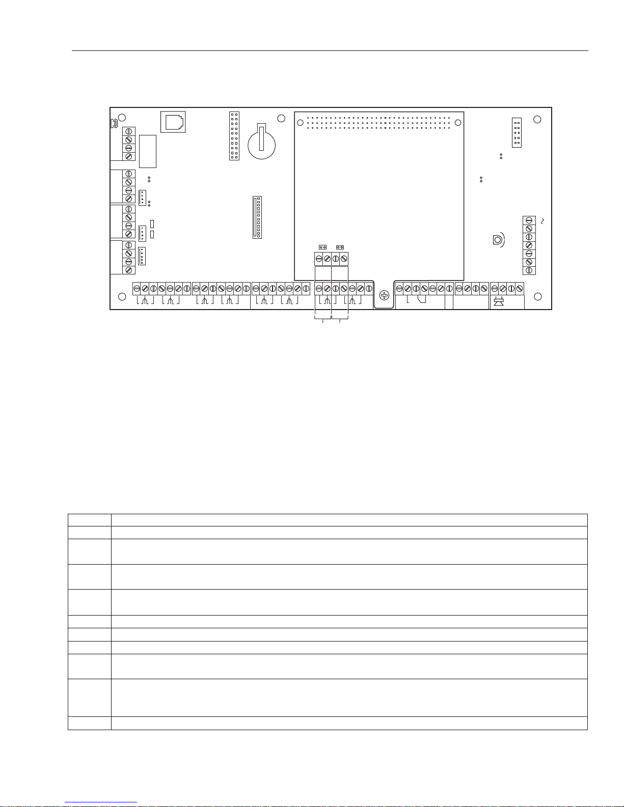
RS485 Expansion Module (GX-520 only)
The RS485 Expansion Module is attached to the GX-520 to give 2 extra RS485 (AB) lines.
SKT2
LINE
A
PHONE
B
AB
B1
A1
GND
+12V
B2
A2
GND
+12V
TX
RX
CTS
RTS
NOTE 1:
RS485 DATA BUS LINES MUST USE DAISY CHAIN
WIRING BETWEEN MODULES.
NOTE 2:
EACH END OF THE RS485 DATA BUS MUST BE
TERMINATED WITH A 680 OHM RESISTOR ACROSS
THE A&B WIRES. IF THE PANEL DOES NOT FORM
ONE END OF THE BUS, REMOVE THE LINK TO DISABLE
THE 680 OHM RESISTOR.
+12V
6
2
1
3
0V
0V
5
4
RIO 0
0V
RS485
EXPANSION
MODULE
RS485 LINE 4 680 Ω TERMINATION (SEE NOTE 2).
RS485 LINE 3 680 Ω TERMINATION (SEE NOTE 2).
B3
A4
B4
A3
+12V
8
7
0V
2
1
0V
+12V
6
5
4
3
0V
RIO 1
RS485
0V
LINE 3
(NOTE 1)
RS485
LINE 4
7
(NOTE 1)
+12V
8
0V
Figure 2-5. RS485 Expansion Module
ONON
44 55
22 33
66
11
77 88
C
N/C
N/O
1
4
3
2
RIO 0
+12V
4
2
13
RIO 1
AUX
TAMP
AC
LID
TAMP
-BAT
+BAT
14.5
G
N
D
GX-005-V1
Transformer Installation Instructions
Use the supplied 1451 Transformer. This transformer provides 18VAC/72VA secondary winding for
powering the control and has a manually resettable circuit breaker mounted inside a protective metal
enclosure. To connect the 1451 transformer to the control, perform the following steps (refer to Figure 2-6):
Notes: 1. Make sure the circuit breaker that controls the circuit providing power to the control unit is in the OFF position.
2. The 120VAC circuit that the transformer is connected to should be dedicated to powering the control unit, should
provide power continuously for 24 hours, and should not be controlled by a wall switch.
3. All circuits are power limited except the output of the 1451 transformer and the battery.
Step Action
1. Remove the front cover.
2. Mount the 1451 transformer enclosure to the wall near the control panel. The enclosure has four
mounting holes on its back surface for this purpose.
3. Identify the circuit breaker or fuse controlling the circuit furnishing power to the control unit.
Make sure it is in the OFF position.
4.
5. Use wire nuts to splice the 120VAC wires to the transformer’s white and black primary leads.
6. Connect the earth ground post on the back of the enclosure to a good earth ground.
7. Run 16AWG wire in conduit from the enclosure to the control panel.
8. Route the wire through a knockout on the left-hand side of the control unit's enclosure. Tie-wrap it
9. Use wire nuts to splice the transformer blue 18VAC secondary leads to the 16AWG wire. Connect
10. Replace the front cover of the enclosure and fasten it with the screws supplied.
Run 120VAC wiring from the circuit breaker or fuse to the enclosure in conduit. A dedicated
circuit must be used.
to a tie wrap loop near the knockout to separate it from other power-limited wiring.
the 16AWG wire at the control panel to the AC terminals on the control panel. See Figure 2-4 for
exact location of the AC connections on the PCB.
2-5

GX-Series Control Panel Installation and Setup Guide
Connecting the Control Unit to Earth Ground
To connect the system to earth ground, perform the following steps:
Step Action
1. Connect the earth ground post inside the transformer enclosure to a good earth ground (use
grounding methods specified in the National Electric Code).
2. Use a green nut (supplied) to secure the green ground wire to the ground post. The earth ground
wire should be the only wire under this nut.
3. Run 16AWG wire from this post through conduit into the control unit enclosure.
4. Take a ring terminal harness and cut it in half. Connect the wire end of the ring terminal harness
with a wire nut to the 16AWG wire from the conduit and take the ring terminal end and place it
under the mounting plate screw. See Figure 2-6.
5. Take the other end of the ring terminal harness and insert the bare wire end into the ground
(GND) terminal block on the main PCB and place the ring end under the mounting plate screw.
See Figure 2-6.
6. To ground the cabinet door to the cabinet take the ring terminal harness and place both ends on
the mounting post on the door and cabinet and secure it with a washer and green nut. See
Figure 2-6.
PLATE MOUNTING
RUN BELL WIRES
IN CONDUIT
SCREWS (2)
Note: Keep power
limited and non-power
limited wires a
minimum of ¼” apart.
TRANSFORMER
NUT (GRN)
AND LOCKWASHER
CABINET DOOR
1/2" RING
TERMINAL
HARNESS
WIRES MUST
BE RUN IN
CONDUIT
GND WIRE (GRN)
WIRE
NUT
PC
BOARD
PLATE
PLATE MOUNTING
SCREWS (2)
ONO
11
4455
2233
N/O
N
66
C
7788
N/C
F1
DOOR T AMPER
SWITCH LOCATION
CABINET
GND
1/2" RING
TERMINAL
HARNESS
REAR T AMPER
SWITCH LOCATION
RUN ALL REMAINING
WIRE THROUGH HERE
GX-103-V1
Figure 2-6. Installing the Control
Power Requirements
The GX-Series uses 1451 power supply as the primary power source. Because the system power is
distributed over the RS-485 buses, it is important to keep the voltage drops along the buses to a minimum.
Good installation practices will go a long way toward minimizing both the effect of the voltage drops and the
need for adding an external power unit.
Where additional power is needed, an Electronic Security Devices (ESD) SPS-6E power supply can be
introduced at sections of the bus. The power supply will provide power for its associated device and for
additional sections of the RS-485 bus, as well.
2-6
GX-Series Control Panel Installation and Setup Guide
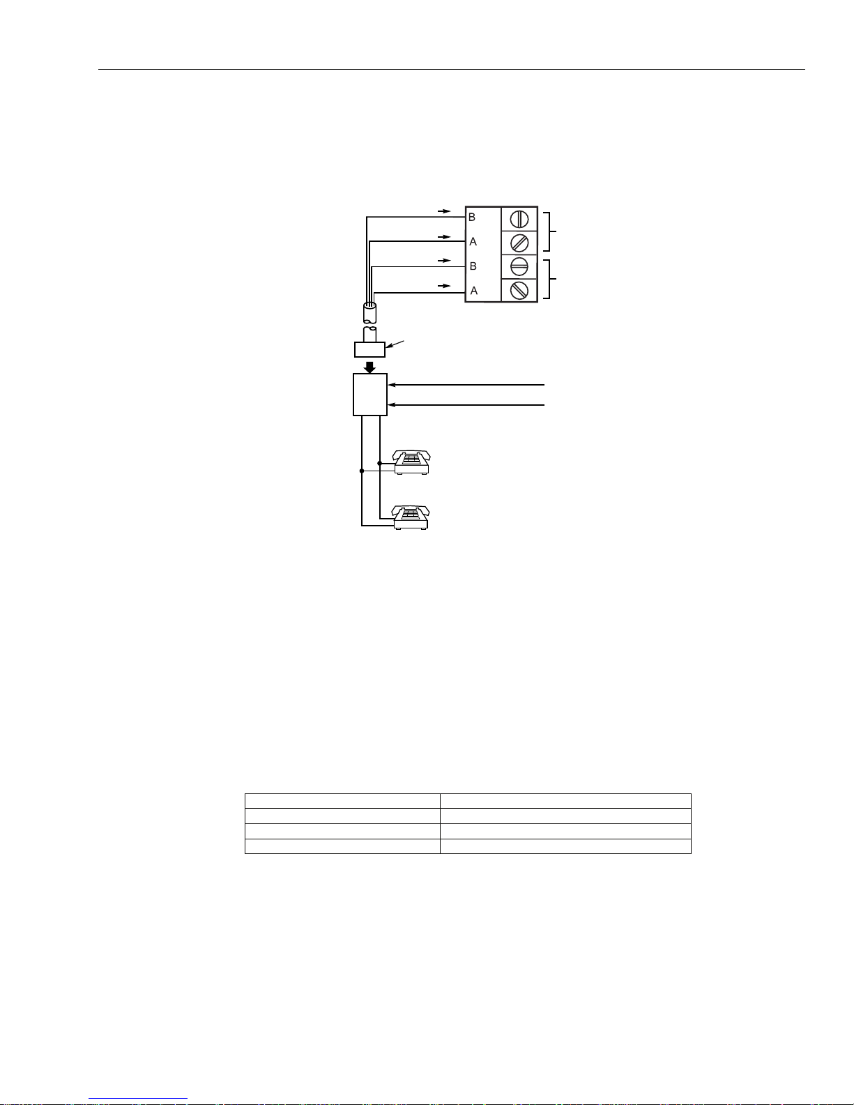
Connecting the GX-Series to the PSTN
Connect incoming phone line and handset wiring to the main terminal block (via an RJ31X jack) as shown in
Figure 2-7. Wire colors represent the colors of the cable to the RJ31X jack. MX-8000 or 685 dialers are for
supplementary central station use. Computer is the primary central station.
TERMINALS
ON CONTROL
LINE
LINE
PHONE
PHONE
DIRECT
CONNECT
CORD
RED (RING)
GREEN (TIP)
GREY (RING)
BROWN (TIP)
RJ31X
JACK
RING
PLUG
TIP
INCOMING TELECOM LINE
RING
TIP
PREMISES
PHONES
GX-007-V0
Figure 2-7. Connecting the GX-Series to the PSTN (Incoming Telephone Line)
Connect the on-board Telecom Module to the PSTN as shown in the diagram.
Notes: 1. Terminals 1 and 2 must be hard-wired to LINE A (Tip) and B (Ring) terminals on the GX-Series PCB.
The connection is polarity independent.
2. It is strongly recommended that the GX-Series panel is the only device on the line.
3. Audio module not evaluated by UL.
Note: If a Digital Subscriber Line (DSL) is used, a suitable filter must be used for the phone line.
Line Monitoring
Under normal idle state conditions, the on-board Telecom Module monitors the PSTN line.
PSTN LED (Green): If a telephone line fail is detected by the Audio Interface this LED will flash repeatedly
at: 200ms ON/200ms OFF. When the telephone line fail condition clears this flashing LED will then go OFF.
LED Flash Rate (seconds) Meaning
OFF No DC supply
ON - 01s, OFF - 0.9s Normal Communication
09 ON / 0.1 OFF Very poor communications
Table 2-2. Communications Status
Stand-By Battery
The GX-Series control panels can accommodate up to 2 x 17 Ah batteries. Ensure that the battery connector
leads on the control panel Powers Supply Unit (PSU) are connected to the correct terminals on the battery.
CAUTION: There is a risk of explosion if the battery is replaced by an incorrect type. Dispose of used batteries
according to the instructions.
2-7

GX-Series Control Panel Installation and Setup Guide
Control Panel Battery
-BAT -ve terminal
+BAT +ve terminal
Table 2-3. Battery/Control Panel connections
NOTES: 12V 7AH battery capacity is required for emergency standby for at least 4 hours.
Two 12V 7AH batteries are required for standby power in UL installations.
Accommodation of 2 x 17 Ah batteries not evaluated by UL.
When connecting batteries in parallel:
- Battery normally need not be replaced for at least 3 years.
- Use batteries from the same manufacturer and with the same voltage and capacity rating.
- Use batteries with approximately the same age and state of charge.
- Use cables provided, and observe polarity!
- It is recommended that all batteries be replaced at the same time, even if only one battery has
become weak.
Battery Start-up
The system can be powered up via the Battery Start-up jumper if there is no AC power. To do this, short
out the Battery Start-up jumper for the duration of the configuration process only. Never leave the Battery
Start-up connected or else deep discharge of the Stand-by Battery will occur.
Power Monitoring Characteristics: Low battery level: 11.2V
Deep discharge protection: 10.2V
Overvoltage protection: 14.7V
Internally the PSU is split in two in order to ensure sufficient current is always available for stand-by
battery recharge. The PSU capacity is broken down as follows:
• Battery: 1.25A
• Control PCB: 0.25A
• AUX +12V: 1.00A
The PSU is available for zones/outputs and peripherals.
Memory
The GX-Series control panel has a built-in memory chip with its own battery backup on the main PCB. This
allows the panel to retain the system configuration, programming details and the event log for up to a year
when both the mains power and standby battery have been disconnected. The memory backup battery must
be kept in place to retain the memory during a mains failure. Re-apply power, this is known as a warm
start.
To completely erase the system memory and return to the default settings, place a piece of thin card between
the retaining clip and the memory backup battery then remove all power to the PCB for one minute. Reapply power and remove the card. This is known as a cold start.
The memory backup battery should be replaced every 5 years, by a trained installer only.
Memory backup battery replacement:
1. Remove memory backup battery with a small flat head screwdriver.
2. Replace with a good battery.
3. Reconnect mains supply.
4. Reconnect 12V battery.
CAUTION: There is a risk of explosion if the battery is replaced by an incorrect type. Dispose of used batteries
according to the instructions.
Do not overstress the retaining clip when removing and installing the backup battery. The clip must
maintain a firm pressure on the backup battery at all times.
Replacement Batteries: Panasonic CR2025; or Varta Batteries CR2025.
2-8
GX-Series Control Panel Installation and Setup Guide
RS485 Data Communication Bus (AB Lines)
Communication between the GX-Series control panels and the modules attached to the system takes place
on the AB lines. The communication protocol is RS485 format. The control panel constantly monitors the
modules attached to it. A break in the communication from any of the modules generates a module tamper
alarm.
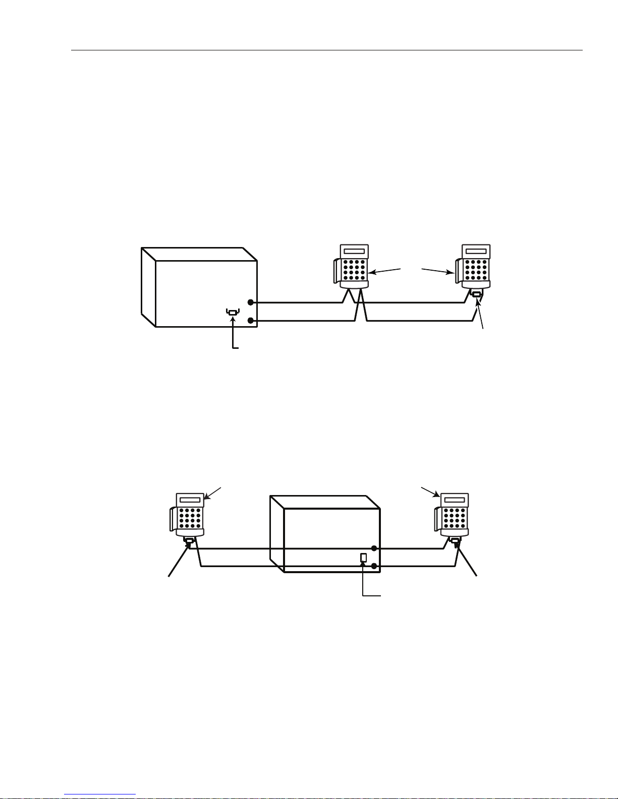
RS485 Wiring Configurations
The system must be wired in a daisy-chain configuration. That is the A line from the previous module is
connected to the A terminal of the current module and then on to the A line of the next module. The RS485
(AB) line must have a 680 • resistor installed across the A and B terminals of the last module on the line. If
two lines are connected, both ends must be terminated with 680 • resistors and the appropriate link (LK3 or
LK5) removed.
Keypad
OR
GX-Series
Control
Panel
680 Ω
A
B
Fit LK3/LK5 on PCB
A
B
Figure 2-8. Daisy Chain Configuration
Each AB line can run in two directions from the control panel.
• Remove link LK3 (RS485 line 1) or link LK5 (RS485 line 2).
• Run two lines from the A and B terminals of the line.
• Terminate both Ends of Line (EOL) with a 680 ohm resistor.
Module
AB
680 Ω EOL
GX-008-V2
NOTE: It is permissible to have different configurations on each line. For example, line 1 – Daisy chain; line 2 -
twin AB daisy chain.
Keypad
OR
Module
Keypad
OR
Module
GX-Series
Control
A
680 Ω EOL
B
Panel
A
B
Remove
LK3/LK5
B
A
680 Ω EOL
GX-009-V2
Figure 2-9. Twin AB Line Daisy-Chain configuration
RS485 Wiring Recommendations
To ensure that the system communicates at the maximum level of efficiency, the following recommendations
must be adhered to:
2-9

GX-Series Control Panel Installation and Setup Guide
1. The maximum number of devices on each line is shown in Table 2-5:
GX-48 (Line 1 only) GX-520 (Lines 1-4)
Keypads
Touch Center
RIO's
DCM
RS232
Telecoms
Printer
Ethernet
8 8 per line
1 1 per line
4
4 8 per line
1 1 (line 1 only)
1 1 (line 1 only)
1 1 (line 1 only)
1 1 (line 1 only)
Table 2-4. Communication Devices
2. Minimum wire gauge for field wiring circuits is 22AWG.
3. The system must be wired in a daisy-chain configuration. Spur and star configurations must not be
used as they reduce the immunity to electrical interference.
4. The cable used must screened twisted pair (Part No W002) to connect the RS485 (AB) line. This would
be CAT5 or Belden 8723 equivalent.
5. Shielded twisted pair cable, where used, is connected to the cabinet ground rod on the GX-Series control
panel using the P-clip and nut supplied (refer to Figure 2-10).
6. The RS485 (AB) line must have a 680 • resistor installed across the A and B terminals of the last
module on the line. If twin lines are connected, both ends must be terminated with 680 • resistors and
the appropriate link on the control panel PCB must be removed (refer to Figure 2-9).
7. There must only be a single AB pair of wires in each of the cables.
8. Supply voltage to the devices is 12 VDC.
9. The power supply in the GX-Series control panel and remote power supplies must not be connected in parallel.
10. The 0 V of all remote power supplies should be connected in common to the 0 V of the GX-Series control
panel.
11. Ensure that any extension loudspeakers are not wired in the same cable as an AB pair of wires.
12. Where possible, ensure that the AB cable is at least 30cm away from any other cables.
13. Where possible, ensure that the AB cable does not run parallel to other cables for extended distances
(maximum 5 meters).
P-clip
AB connectors
A
data line
RS 485 cable
Nut
P-clip
Ground Rod
(threaded)
Figure 2-10. Connection of cable screen using P-Clip
B
data line
Cable screen
GX-010-V1
2-10

GX-Series Control Panel Installation and Setup Guide
Zones
The default setting for the zones on the GX-Series are as follows:
Zone 1001 = Final
Zone 1002 = Exit
All remaining zones = Intruder
Zone Addresses
Each zone has a four digit address; 1004, 4136. The address is made up of three reference numbers as shown
in the following figure:
Example: 3057
3
05 7
Represents Panel
Line No.
GX-Series
PANEL
1 2 3 4
Represents
RIO Address
RIO
ADDRESS 05
Represents
Zone No. 1-8 on
RIO
ZONE 7
GX-011-V2
Figure 2-11. Zone Addresses
For example, zone 3057 is the detector connected to line 3, RIO 05, zone 7.
Zone Addressing with On-board RIO Switch (Line 0 Switch)
The RIO switch (SW3, dipswitch 8) controls the ordering of the on-board RIO’s. This dipswitch must be set
before powering up the panel. Setting the switch to ON sets the on-board RIO1 to operate on line 0 and
allows a RIO addressed as 1 to be connected to line 1, giving a total of 15 RIO’s on a GX-520. The RIO switch
only needs to be activated if the maximum number of RIO’s will be used.
NOTE: The RIO switch is not functional on other panel variants. It defaults to the Switch off configuration.
Switch off (default)
When the switch is set to this mode, the on-board RIO’s configure to the following addresses:
On-board RIO0 Zone address range: 1001-1008 Outputs: 1001-1004
On-board RIO1 Zone address range: 1011-1018 Outputs: 1011-1014
Switch on
When the switch is set to this mode, the on-board RIO’s configure to the following addresses:
On-board RIO0 Zone address range: 1001-1008 Outputs: 1011-1014
On-board RIO1 Zone address range: 0011-0018 Outputs: 0011-0014
Max No. of
External
RIO's
(Line 1)
Panel On-Board RIO Address Range
Total on-
board
Zones
GX-48 1001 - 1008, 1011 - 1018 (switch off) 16 4 2-5 48
GX-520
1001 - 1008, 1011 - 1018 (switch off) 16 15 2 - 9, A - F 520
1001 - 1008, 0011 - 0018 (switch on) 16 14 1 – 9, A - F 520
Valid
External RIO
Addresses
(Line 1)
Total Zone
Addresses
(Switch ON)
Table 2-5. Zone Address Ranges
2-11
GX-Series Control Panel Installation and Setup Guide
Wiring Zones
The zones on GX-Series panels can be Double Balanced (default) or End of Line. Zones can be programmed
with different resistance ranges for zone status activation (see Parameter 51.46 = Parameters.Zone
Resistance). Refer to Table 2-7 (Double Balanced) or Table 2-9 (End of Line) for details of the zone
resistance and resulting conditions. The system default is Option 9, giving fault monitoring on 1k double
balanced wiring.
NOTE: The circuit debounce time (the period the zone must remain in a state to register a change in condition) is
300 milliseconds by defaul t .
Option 01 - 1k Option 03 – 2.2k Option 05 – 4.7k Option 07 – 5.6k Option 09 - 1k Fault
Tamper S/C 0 – 800 0 – 1800 0 – 3700 0 -1400 0 - 800
Low Res 800 – 900 1800 – 2000 3700 – 4200 1400 – 2800 800 - 900
Normal 900 – 1200 2000 – 2500 4200 – 5500 2800 – 8400 900 -1200
High Res 1200 – 1300 2500 – 2700 5500 – 6500 8400 – 9800 1200 - 1300
Open 1300 – 12000 2700 – 12000 6500 – 19000 9800 – 12600 1300 - 3500
Fault - - - - 3500 - 4500
Masked 12000 – 19000 12000 – 15000 19000 – 22000 12600 – 22000 4500 - 19000
Tamper O/C 19000 – infinity 15000 – infinity 22000 – infinity 22000 – infinity 19000 - infinity
Table 2-6. Double Balanced Zone Resistance and Conditions
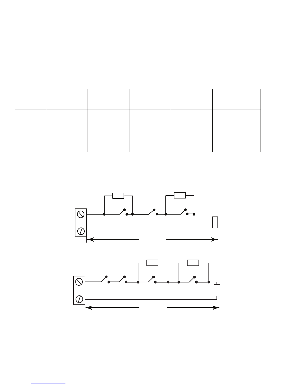
Option 09 - 1k Fault Double-balanced (default)
The wiring in Figure 2-12 should be used if the detector uses combined fault and mask signaling. A mask
condition is generated if an alarm and fault are signaled at the same time. Alternatively, if the detector has
separate fault and mask indications then the wiring in Figure 2-13 should be used.
3k
1k
GX-012-V1
Zone
1k
Alarm N/C Fault N/C
Tamper N/C
328 ft (100 m)
Figure 2-12. Option 09 - Double balanced 1k Fault Monitoring Wiring
3k 12k
Zone
Alarm N/C
Tamper N/C
Fault N/C
328 ft (100 m)
Anti-mask N/C
1k
GX-013-V2
Figure 2-13. Option 09 - Double balanced 1k Fault/Mask Monitoring Wiring
NOTES: For UL Installations, use 1K Ohm single EOL resistor configurations; the maximum loop impedance is 100 Ohms.
N/C = Normally Closed.
2-12

GX-Series Control Panel Installation and Setup Guide
When this wiring mode is employed, only one detector which can report fault conditions should be connected
to the zone. A maximum of two detectors or contacts of any type should be connected to a zone when this
mode is selected. It is recommended that zone cable lengths are kept below 328 feet (100 m) in this
configuration.
NOTE: The recommended maximum cable run from a zone to a detector is 1640 feet (500 m) in all other
configurations.
Option 02 - 1k Option 04 – 2.2k Option 06 – 4.7k Option 08 – 5.6k Option 10 -1k Fault
Tamper S/C 0 - 800 0 – 1800 0 – 3700 0 – 1400 0 - 800
Low Res 800 – 900 1800 – 2000 3700 – 4200 1400 – 2800 800 - 900
Normal 900 – 1200 2000 – 2500 4200 – 5500 2800 – 8400 900 - 1200
High Res 1200 – 1300 2500 – 2700 5500 – 6500 8400 – 9800 1200 - 1300
Fault - - - - 1300 - 4500
Masked 1300 – 12000 2700 – 12000 6500 – 19000 9800 – 19000 4500 - 19000
Open 12000 – infinity 12000 – infinity 19000 – infinity 19000 – infinity 19000 – infinity
Table 2-7. End of Line Zone Resistance and Conditions
Option 10 - 1k Fault End-Of-Line
The wiring in Figure 2-14 should be used if the mode is end-of-line. Fault and mask indications can only be
signaled if the detector has separate fault and mask indications.
3k 12k
Zone
Alarm N/C
Tamper N/C
Fault N/C
328 ft (100 m)
Anti-mask N/C
1k
GX-014-V2
Figure 2-14. Option 10 - End of Line Zone/Detector wiring
When this wiring mode is employed, only one detector which can report fault conditions should be connected
to the zone. A maximum of two detectors or contacts of any type should be connected to a zone when this
mode is selected. It is recommended that zone cable lengths are kept below 100m in this configuration.
NOTE: The recommended maximum cable run from a zone to a detector is 1640 feet (500 m) in all other
configurations.
Wiring Multiple Detectors
Multiple detectors can be wired into a single zone when using preset 1 as shown in Figure 2-15. The
maximum number of detectors that can be connected to a single zone is ten.
(10 max)
N/C T AMP
N/C
Alarm
N/C
Alarm Alarm Alarm
N/C
N/C N/C
Zone
1k
1%
1k
1%
1k
1% 1%
1640 ft (500 m)
1k
Figure 2-15. Zone to Multiple Detector Wiring
2-13
1%
1k
GX-015-V1

GX-Series Control Panel Installation and Setup Guide
Wiring Keyswitches
Latching or spring loaded keyswitches can be used to set (arm) and unset (disarm) the GX-Series panels;
option 52 = PROGRAM ZONES has provision to accommodate both types of transition. If the keyswitch
latches, the transition from 1 k• to 2 k• initiates the setting (arming) procedure of an unset (disarmed)
system, the transition from 2 k• to 1 k• instantly unsets (disarms) a set (armed) system. If the system is
already set (armed), then the transition from 1 k• to 2 k• has no effect. If the system is unset (disarmed),
the transition from 2 k• to 1 k• has no effect. This is programmed as a * Keyswitch in the PROGRAM
ZONES option. If the keyswitch is spring-loaded (returns to its normal position), the transition from 1 k• to
2 k• initiates the setting (arming) procedure of an unset (disarmed) system and instantly unsets (disarms) a
set (armed) system, the transition from 2 k• to 1 k• - the return to the normal position - has no effect. This
is programmed as a Keyswitch in the PROGRAM ZONES option.
Wiring Terminator Buttons
Zones programmed as Push-Set (terminator) buttons can be open going closed (2 k• to 1 k•) or closed going
open (1 k• to 2 k•). The first activation of the terminator button initializes its status to the system.
NOTE: The first activation of a termina tor may not set (a rm) the syste m as this can be th e initializ ation ro utine . If the
system continues setting (arming), push the button again. The system will set (arm) on the second push. This
initialization only occur s on the fi rst setti ng (a rming). All sub sequen t setting (arming ) routine s set (ar m) on the
first push of th e te rminat o r. The w i ring of the t e rminat or an d keyswi t ch z one ty pe i s show n in Fi gu re 2 -16:
Keyswitch
zone
Push-set
zone
Open - Closed
1k
1%
1k to unset (disarm)
2k to set (arm)
1k
1%
OR
1640 ft (500 m)
Closed - Open
1%
1k
1%
1k
1%
1k
GX-016-V2
Figure 2-16. Terminator and Keyswitch Zone Wiring
Outputs
The GX-Series control panel on-board outputs are detailed in the Table 2-9:
NOTE: The maximum current draw for the +12V AUX outputs is 1A, and for the switched AUX outputs is 400mA
(see TB1 – TB6 in Figure 2-4.) The total maximum load for output addresses 1001, 1003 – 1004 and
1011 – 1014 = 400 mA.
Output Address
Line 0
Default
1001 1001 Bells Transistorized 12V, s ee note above Positive
1002 1002 Strobe Single Pole Change
1003 1003 PA Tr ansistorized 12V, see note above Positive
1004 1004 Reset Transistorized 12V, see note abov e Positive
1011 0011 Set Transistorized 12V, see note above Positive
1012 0012 Intruder Transistorized 12V, see note a bove Positive
1013 0013 Confirm Transistorized 12V, see note above Positive
1014 0014 Reset Transistorized 12V, see note abov e Positive
Enable
Default Function Type Rating
30V, 1A De-energized
Over Relay (SPCO)
Normal State
(with 3k3 pull-up)
Table 2-8. Outputs
2-14

GX-Series Control Panel Installation and Setup Guide
Output Applications
The outputs on the GX-Series panels, with the exception of the SPCO relay output, are transistorized
outputs; negative applied (positive removed) by default. These can switch up to 400mA and can be used to
drive the necessary output devices.
NOTE: The polarity of each output can be changed using option 53 = PROGRAM OUTPUTS
Common Collector Output
+12 V
3.3k
Output
0 V
Use 3.3k Ohm resistor for
open-collector output
Figure 2-17. Output Configuration and Typical Applications
Typical Applications
A) LED Indicator
LED
1k (Standard)
B) Bell Output
C) Zone Outputs
Must be opencollector output
NOTE: If using integrated output, replace the
*
1kOhm resistance with 680 Ohm resistor.
Bell
1k
1k
1%
1%
*
+12 V
+ 12 V
Zone
GX-017-V2
Note: For the appropriate 3.3kΩ pull-up resistor refer to DIP switch SW3 (Table 2-1).
The relay output is a single pole change over (SPCO); this can be used to drive output devices that require a
clean set of contacts, isolated from the output voltage.
Horn
Single Pole
Change - Over
relay contacts
Normally
closed
Normally open
+12 V
0 V
GX-018-V1
Figure 2-18. Single Pole Change–Over Relay Output Configuration and Typical application
Trigger Header
The Trigger Header on the GX-Series is a set of pins that consist of programmable outputs for an external
communication module. The connection is via an optional ribbon cable.
Trig 1-6
There are six trigger outputs that can be used as communication triggers, but can also be used for any other
purpose. By default these outputs are programmed as positive. They are designed to sink current (to 0V) not
source current (from 12V). The functions of these outputs are shown in Table 2-9:
2-15

GX-Series Control Panel Installation and Setup Guide
Output Address Default function Current (mA)
0001 Fire 100
0002 Panic 100
0003 Intruder 100
0004 Set (Arm) 100
0005 Omit (Bypass) 100
0006 Confirm 100
Table 2-9. Trigger Output functions
The function of the trigger outputs can be programmed in menu option 53 = Program Outputs.
NOTE: Not evaluated by UL.
Supply
A 100 mA, 12V output is also provided.
+12V
Not Used
Not Used
Trig 6
Trig 5
Trig 4
Trig 3
Trig 2
Trig 1
Not Used
Not Used
GX-019-V0
Figure 2-19 Trigger Header
GND
SPI Header
The SPI (Serial Peripheral Interface) key is an engineering peripheral used for copy/overwriting
programming data and carrying out software upgrades.
Fitting the SPI Key
The SPI key is inserted directly on to the GX-Series control panel.
CAUTION: Always power down the panel BEFORE removing or connecting the SPI key. Failure to do so may
result in damage to the SPI key. Never “hot-plug” the SPI key.
The SPI Key has a 10-way connector. These locate on to the 10 pins of the SPI Program Header (see Figures
below).
NOTE: The SPI Key should only be inserted in the direction shown in Figure 2-19.
SPI KEY
CONTROL PANEL
10-WAY
CONNECTOR
HINGED
CAP
Figure 2-20. SPI Key
GX-020-V0
Figure 2-21. Location of SPI Key on Program Header
(PAR TIAL VIEW)
INSERTED
HERE
SPI PROGRAM
HEADER
GX-021-V1
2-16

GX-Series Control Panel Installation and Setup Guide
1. Release the hinged cap to expose the 10-way connector.
2. Plug the SPI Key on to the Program Header on the GX-Series control panel.
Removing the SPI Key
CAUTION: Always power down the panel BEFORE removing or connecting the SPI key. Failure to do so may
result in damage to the SPI key. Never “hot-plug” the SPI key.
1. Remove the SPI Key from the Program Header on the GX-Series control panel.
2. Secure the hinged cap to protect the 10-way connector.
2-17

GX-Series Control Panel Installation and Setup Guide
2-18
GX-Series Control Panel Installation and Setup Guide
SECTION 3: PERIPHERALS
General
The following peripherals can be connected to the GX-Series panel:
All bus lines: Mk7 Keypad; TouchCenter; Door Control Module (DCM);
Remote Input Output module (RIO).
Bus line 1 only: Ethernet.
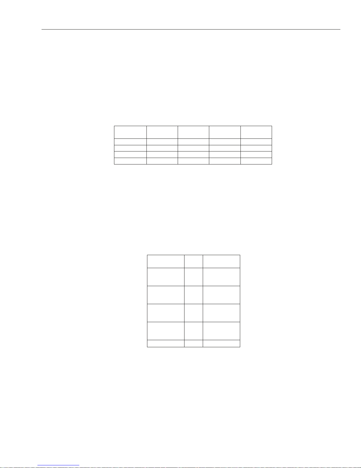
Wiring
The following table shows the wiring between the GX-Series panel and the different peripherals.
Panel Keypad
+12V + + Vin +12V
GND - - - GND
A A G A A
B B Y B B
Touch
Center
Table 3-1. Peripheral Wiring to GX-Series Panel
NOTE: Do not connect +12V terminals between panels and
remote power supplies.
Configuring
New peripherals will be configured onto the system at system power up or on leaving programming mode.
Changes to peripheral addresses will only take effect when the peripheral is re-powered.
Addressing
The address on most peripherals is set by either jumpers or a rotary switch. These must be set before the
system is powered up. Table 3-2 shows the available peripheral addresses.
Peripheral Line
Mk7 Keypad 1
TouchCenter 1 1
RIO 1
DCM 1
Ethernet 1 (B)
2
3-4
2
3-4
2
3-4
2
3-4
RIO &
DCM
VALID
ADDRESSES
0-2, B-F
0-6, F
0-6, F
0-2
0-3
0-3
2
2
-9 & A-F
0-9 & A-F
0-9 & A-F
0-7
0-7
0-7
Audio
Interface
NOTES: 1. A single TouchCenter can be installed on each bus line.
2. If RIO 2 on-board is set to line 0 (Dip SW 8) then the first external RIO can use address
1 to give an extra 8 zones where needed.
Connecting the RIO
The RIO can only be connected to the system while engineer mode is accessed. The RS485 (AB) line of the
GX-Series RIO must be wired in parallel (daisy-chain configuration) with the RS485 (AB) line of any
keypads connected to the system. The RIO requires 12 VDC and 40 mA. This can be supplied from the
Table 3-2. GX-Series Peripheral Addresses
3-1

GX-Series Control Panel Installation and Setup Guide
control panel power supply or from a remote power supply if the distance causes a large voltage drop on the
cable.
Connect the RIO terminals as follows:
+12 V (either control panel, keypad or remote power supply);
–0 V or ground (either control panel, keypad or remote power supply);
A to the A terminal of the previous module (or control panel if RIO is the first on the line);
B to the B terminal of the previous module (or control panel if RIO is the first on the line).
NOTE: If the RIO is the last module on the line, connect a 680 Ω EOL resistor across the A and B terminals.
Configuring the RIO
The added RIO is configured into the system on exiting from engineer mode. If the message XX Mod Added
[<],[>] To View is displayed, the system has recognized that a new module is present. Press the A> or <B
keys to confirm that the RIO has been added. If this message is not displayed or the RIO is not on the list of
added modules, then the RIO is not communicating with the control panel or has been set to the same
address as the RIO already connected to the system. The flash rate of the red LED (LED1) on the RIO
indicates the status of the communication with the control panel - refer to Table 3-3.
Flash Rate (seconds) Meaning
0.1 ON / 0.9 OFF Normal communications
OFF No DC supply
1.5 ON / 1.5 OFF RIO has not been configured into system
0.2 ON / 0.2 OFF RIO has lost communication with system
0.9 ON / 0.1 OFF Very poor communications
Table 3-3. RIO LED Flash Rates
RIO Zones
The GX-Series RIO has eight programmable zones. These default to INTRUDER. Each zone is Double
Balance monitored with a 1 k• resistor in series with the zone detector and a 1 k• (1%) resistor in parallel
across the detector switch. The change to 2 k• (1%) resistance registers the zone as open/alarm.
RIO Outputs
The RIO has four transistorized outputs. Each output is connected to +12 V via a 3.3k• pull-up resistor
(refer to Table 3-4). When an output is activated, the load is switched to the negative supply voltage (ground
or 0 V) of the RIO. The total current available from the RIO outputs 1 - 4 is 700 mA. The default functions
and pull-up resistors of each RIO output, when connected to a GX-Series are shown in Table 3-4.
Output No. Function Maxium Load Pull-up Resistor
1 Bells 400 mA R1
2 Strobe 100 mA R3
3 PA (Personal Attack) 100 mA R5
4 Reset 100 mA R7
Table 3-4. RIO Output Default Functions
Ethernet Module
NOTES: For UL installations use a DTK-MRJ45C5E Ethernet surge protector.
In UL 1076 compliant systems, the Ethernet module must be used as the primary means of
communication.
In UL installations, do not use an Ethernet card in wireless LAN or WAN configurations.
The Ethernet Module is an optional add-on to the GX-Series control panel. It is a highly intelligent and
compact module, combining alarm signaling, remote servicing and integrated facilities over Ethernet LAN
and/or WAN. The Ethernet Module connects to 10 Base T Ethernet networks both supporting UDP/IP and
TCP/IP protocols. The Ethernet module supports the following features:
3-2

GX-Series Control Panel Installation and Setup Guide
• Full alarm signaling on SIA
• Microtech protocol signaling with Event Monitoring Software
• Remote servicing via remote servicing software
PROGRAMMING
HEADER
LED3
PROCESSOR
LED1
ENGINEER
SOCKET
+
S
-
A
LINE
B
SKT1
PROCESSOR
LED2
SKT2
GX-027-V0
Figure 3-4. Ethernet PCB Layout
NOTES: The position of components on the Ethernet PCB may vary with different hardware revisions.
For UL installations, use LAN for all Ethernet connections.
Configuring the Ethernet Module
The added Ethernet Module is configured into the system on exiting from engineer mode and is allocated
keypad address 15 (B). If the message XX Mod Added [<],[>] To View is displayed, the system has
recognized that a new module is present. Press the A> or <B keys to confirm that com 4 has been added. If
this message is not displayed or the Ethernet Module is not on the list of added modules, then the Ethernet
Module is not communicating with the control panel. The flash rate of the red LED (LED3) on the Ethernet
Module indicates the status of the communication with the control.
Ethernet Communication
The green LED (LED1) is illuminated when the Ethernet Module is connected to Ethernet. The amber LED
(LED2) flashes when the Ethernet Module is sending or receiving data. For further information regarding
the Ethernet Module, refer to Ethernet Module, Installation Instructions (800-07482).
Remote Servicing Suite
Remote Servicing Suite (RSS) is an advanced PC based application that allows full remote servicing of GXSeries systems. Functions include configuration and programming, control and diagnostic servicing. RSS
also includes an Event Monitoring application. Event Monitoring is an advanced, high performance software
program that allows a PC to receive and store detailed event and alarm information from GX-Series control
panels.
Minimum PC requirements for RSS package, for both Primary and Back-Up Central Station Receivers
Operating system: Windows XP, Vista
Processor: P4 2.4Ghz minimum
Memory: 512MB minimum
Hard Disk: 170GB minimum
Monitoring Software: Revision Level V5.33.xxx (Where xxx are feature upgrades and bug fixes)
3-3

GX-Series Control Panel Installation and Setup Guide
Operating RSS Software on the Primary or Backup Computer
1. Open the Frontshell + Commserver program.
2. Enter a user name and password [defaults are manager and password, respectively].
3. Double click on the required account name, and the V6 application opens up.
4. Return to the Start Menu and open the Event Monitor.
The RSS package is defaulted to show 100 screen events. To view more than 100 events, open the Setup
Menu, and then System Parameters. Enter a password and then enter the desired value for “Screen
Events.”
During RSS operation, if the computer stops receiving event messages and “line fail” appears, or the monitor
turns black and the computer resets, the secondary computer must be used.
To set up the backup computer:
1. Power on the backup computer.
2. Open the RSS software as described above.
3. Remove the Ethernet/PSTN line from the primary computer and plug it into the backup computer.
NOTES: The backup computer must have the same or greater system requirements as the primary computer.
The same revision RSS software must be used on both the primary and backup computers.
Performing a System “snapshot” on RSS Software
1. Follow steps 1 - 3 above for operating RSS software.
2. Open the Connect Menu in the V6 application.
3. Select Dial and enter a password or click OK.
4. Once connection is made, open the Communication Menu and open Online Keypad. Online Keypad will
refresh in about five seconds.
UL NOTES:
In UL approved systems the monitoring equipment must use a UL listed uninterruptible power supply (UPS).
To backup the monitoring computer, plug the computer’s AC wire into the UPS.
For UL installations, PC monitoring stations and for UL294 installations Data processing equipment and office
appliance and business equipment used as central supervisory station equipment must meet the below
standards:
UL 114: Standard for Office Appliances and Business Equipment
and
UL 478: Standard for Information Processing and Business Equipment
or
UL 60950: Standard for Information Technology Equipment
UL Installation Requirements
UL
Commercial Burglary Requirements
The following requirements apply to all UL Commercial Burglary installations:
1. All groups must be owned and managed by the same person(s).
2. All groups must be part of one building at one street address.
3. The audible alarm device(s) must be placed where it/they can be heard by all groups.
4. The control cabinet must be protected from unauthorized access. This can be done by installing a tamper
switch on the cabinet door (supplied).
This system is required to be installed with applicable UL Installation Standards, such as UL827.
3-4
 Loading...