

Page 1
Solid State Sensors GT1 Series
Hall Effect Gear Tooth Sensors
TYPICAL APPLICATIONS
Automotive and Heavy Duty Vehicles:
1
Camshaft and crankshaft speed/
position
1
Transmission speed
1
Tachometers
1
Anti-skid/traction control
Industrial:
1
Sprocket speed
1
Chain link conveyor speed and
distance
1
Stop motion detector
1
High speed low cost proximity
1
Tachometers, Counters
GT1 ORDER GUIDE
Catalog Listing Description
1GT101DC Gear Tooth Sensor
FEATURES
1
Senses ferrous metal targets
1
Digital current sinking output (open
collector)
1
Better signal-to-noise ratio than
variable reluctance sensors, excellent
low speed performance, output
amplitude not dependent on RPM
1
Sensor electronically
slight variations in runout and
variations in temperature, simplifying
installation and maintenance
1
Fast operating speed – over 100 kHz
1
EMI resistant
1
Reverse polarity protection and
transient protection (integrated into
Hall I.C.)
1
Wide continuous operating
temperature range (–40
short term to 160
self-adjusts
°
C
°
to 150°C),
GENERAL INFORMATION
1GT1 Series Gear Tooth Sensors use a
magnetically biased Hall effect integrated
circuit to accurately sense movement of
ferrous metal targets. This specially designed I.C., with discrete capacitor and
bias magnet, is sealed in a probe type
package for physical protection and cost
to
effective installation.
Units will function from a 4.5 to 24 VDC
power supply. Output is digital, current
sinking (open collector). Reverse polarity
protection is standard. If power is inadvertently wired backwards, the sensor will
not be damaged. Built-in protection
against pulsed transients to
is also included.
Optimum sensor performance is dependent on the following variables which must
be considered in combination:
1
Target material, geometry, and speed
1
Sensor/target gap
1
Ambient temperature
1
Magnetic material in close proximity
PDFINFO pag e -05 2
+
60V, –40V
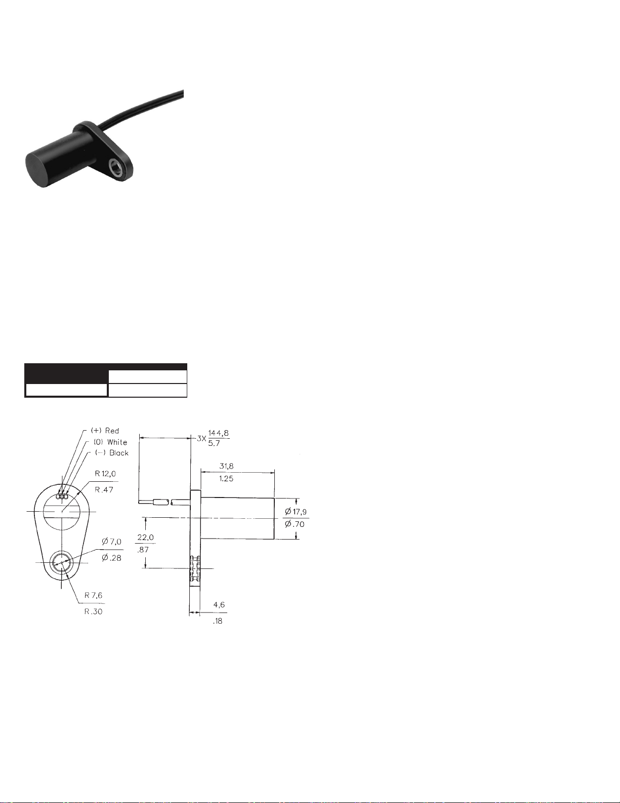
MOUNTING DIMENSIONS (For reference only)
52 Honeywell 1 MICRO SWITCH Sensing and Control11-800-537-6945 USA 1F1-815-235-6847 International 11-800-737-3360 Canada
Page 2

Solid State Sensors GT1 Series
Hall Effect Gear Tooth Sensors
SENSOR SPECIFICATIONS
All values were measured using 1 K pull-up resistor.
Electrical
Characteristics
Absolute
Maximum
Ratings*
Switching
Characteristics**
* As with all solid state components, sensor performance can be expected to deteriorate as
rating limits are approached; however, sensors will not be damaged unless the limits are
exceeded.
** See Reference Target table.
Supply Voltage 4.5 to 24 VDC
Supply Current 10 mA typ., 20 mA max.
Output Voltage (output low) 0.4 V max.
Output Current (output high) 10 µA max. leakage into sensor
Switching Time
Rise (10 to 90%) 15 µsec. max.
Fall (90 to 10%) 1.0 µsec. max.
Supply Voltage (Vs) ±30 VDC continuous
Voltage Externally Applied
To Output (output high) –0.5 to +30 V
Output Current 40 mA sinking
Temperature Range
Storage –40 to 150°(–40 to 302°F)
Operating –40 to 150° C(–40to302°F)
Operate Point 3.7±1.25° (3,28±1,13 mm)
Release Point 4.7±2.50 ° (4,16±2,21 mm)
Differential Travel 8.4±3.70° (7,45±3,34 mm)
TARGET GUIDELINES
The Target Guidelines table provides basic parameters whenan application is not
restricted to a specific target.
Any target wheel that exceeds the following minimum specifications can be
sensed over the entiretemperature range
of –40
°
to 150°C with any sensing gap up
to .080 in.(2,0 mm).This data is based on
a 4 in. (102 mm) diameter wheel, rotating
10 to 3600 RPM.
Reference Target Dimensions
Tooth Height: .200 in. (5,06 mm) min.
Tooth Width: .100 in. (2,54 mm) min.
Tooth Spacing: .400 in. (10,16 mm) min.
Target Thickness: .250 in. (6,35 mm)
Sensor Output (with pull-up resistor added to output circuit)
REFERENCE TARGET/CONDITIONS
Characteristics will varydue to target size,
geometry, location, and material. Sensor
specifications were derived using a coldrolled steel reference target. See table,
right, for reference target configuration
and evaluation conditions.
Target
Diameter: 4 in. (101,6 mm)
Tooth Width: .350 in. (8,89 mm)
Thickness: .250 in. (6,35 mm)
Test Conditions
Air Gap: .040 to .080 in. (1,02 to 2,03 mm)
V Supply: 4.5 to 24 V
RPM: 10 min., 3600 max.
Integral Magnet
PDFINFO p a g e - 0 5 3
Honeywell 1 MICRO SWITCH Sensing and Control11-800-537-6945 USA 1F1-815-235-6847 International 11-800-737-3360 Canada 53
 Loading...