

Honeywell GSMX4G, GSMXCN4G Installation And Setup Manual

IInntteelllliiPPaatth
M
TTM
h
SSeerriieess 44GG GGSSMM CCoommmmuunniiccaattoorr
AAuuttoo--sseelleeccttss OOppttiimmuumm GGSSMM ppaatthh –– 22GG,, 33GG,, oorr 44G
GGSS
MXX44GG
M
/
/
GGSSM
MXXCCNN44GG
ssuuppppoorrttss ttwwoo--wwaayy vvooiiccee
IInnssttaallllaattiioonn aanndd SSeettuupp GGuuiiddee
REG
TX/RX
FAULT
SIGNAL
G
800-10938 1/12 Rev. B

Contents
General Information ........................................................................................... 1
Features.......................................................................................................... 1
Modes of Operation ........................................................................................ 2
Supervision and Fault Detection................................................................... 2
Specifications.................................................................................................. 2
Data Encryption ............................................................................................. 3
Remote Services Features.............................................................................. 3
Testing the System......................................................................................... 3
Compatibility.................................................................................................. 4
Compliance ..................................................................................................... 4
Mount and Wire the Module............................................................................... 4
Select a Mounting Location ........................................................................... 4
Activate the SIM........................................................................................ 4
Verify Satisfactory Signal Strength.......................................................... 5
Mounting the Module on the Control Panel.................................................. 6
Wiring the Module for two-way voice ....................................................... 7
Mounting the Module on the Wall................................................................. 8
Programming the Module................................................................................. 10
Using the AlarmNet Direct Website ........................................................... 10
Using the 7720P Programming Tool ........................................................... 11
Programming Conventions ..................................................................... 12
Using the Control Panel............................................................................... 12
Programming for ECP Mode........................................................................ 12
Programming for 4204 and Two-4204 Emulation Modes........................... 13
4204 Emulation Mode Options ............................................................... 13
Programming Options.................................................................................. 14
ECP Status Codes ........................................................................................ 24
Exiting the Programming Mode .................................................................. 25
Setting Factory Defaults.............................................................................. 25
Registering the Communicator ........................................................................ 26
Registering through the AlarmNet Direct Website.................................... 26
Remote Services....................................................................................... 27
Registering Using the Test Message/Registration Switch ......................... 27
Registering Using the 7720P Programming Tool ....................................... 28
Replacing an existing communicator...................................................... 28
Registering by Phone ................................................................................... 29
Diagnostic Commands ...................................................................................... 30
Module Identification Displays.................................................................... 30
GSM Status Displays ................................................................................... 31
Central Station Messages................................................................................. 34
Uploading and Downloading of Panel Data..................................................... 35
Glossary............................................................................................................. 35
LED and Wiring Information ...................................Inside of Back Cover

GSMX4G / GSMXCN4G Installation and Setup Guide
General Information
The GSMX4G GSM Communicator (GSMXCN4G in Canada), herein referred
to as the communicator, easily connects to your security system's control
panel and sends alarms and messages to AlarmNet for subsequent transfer to
the central monitoring station. It can be mounted directly on the control
panel or remotely.
The new 4G connectivity brings faster GSM data transfers with lower latency
(response time); together it results in speedier data transfers.
The GSMX4G requires an AlarmNet account. For new installations,
please obtain the account information from the central station prior to
programming.
The GSMX4G communicates with AlarmNet using GSM (Global System for
Mobile) technology utilizing GPRS (General Packet Radio Service) as a
means of data transfer. If the GPRS part of the GSM cellular network is
unavailable, it will attempt to send a transmission via SMS (Short Message
Service) also known as a text message.
In addition to alarm reporting, the communicator provides two-way voice
communications with the central station (when used with Honeywell’s AVS
Audio Verification System) and provides upload/downloading capability of
Honeywell's control panel data over the Internet (via the AlarmNet-G
network), using GSM (Global System for Mobile) technology.
UL / ULC
Two-way voice has not been evaluated by UL / ULC.
NOTE: Two-way voice is not compatible with Honeywell Commercial
Control Panels (such as the VISTA-128/250 series).
Features
• Reports fire, burg, and status messages via GSM.
• Internal antenna provides additional security.
• Simple programming using the 7720P programming tool or via the
AlarmNet Direct website.
• Uses 2 way ECP communication with the control panel.
• Sends reports in Contact ID format.
• Supports remote control of alarm system via Remote Services
feature.
• Allows uploading and downloading of control panel data via GSM.
• Fully powered (primary and backup battery) from the control panel.
– 1 –

GSMX4G / GSMXCN4G Installation and Setup Guide
Modes of Operation
• The GSMX4G is for control panels that support ECP communication.
• The control panel treats the communicator as an ECP device, so
ensure to program the control panel with the communicator’s device
address.
• 4204 Mode, and two 4204 Mode operation.
Supervision and Fault Detection
• Network communication failure – In the event the AlarmNet
network does not hear a supervisory message from the communicator within a specified time (“Supervision” option, 24 hours, 30 days,
or none), AlarmNet notifies the central station of a communication
failure.
• Communication path failure – In the event the communicator
detects a communication path failure, the control panel can be
notified of a trouble condition with the communicator after a
specified time has elapsed.
Specifications
Dimensions: 4 x 7 x 1.75 inches
Input Voltage: 12VDC (powered via the ECP bus.)
Standby Current: 65mA
Active Current: 380mA
Operating temperature: –20º to +55ºC, for UL/ULC installations 0ºC to +49ºC
Storage temperature: –40º to +70ºC
Humidity: 0 to 95% relative humidity, non-condensing
(UL installations 0% to 85%; for ULC installations 0% to 93%)
Altitude: to 10,000 ft. operating, to 40,000 ft. storage
Frequency Bands
2G GMS/GPRS/EDGE Quad Band, 850/900/1800/1900 MHz
3G/4G UMTS/HSPA+ Band V, Band II
Output Power
2G GPRS +33dBm, GMSK modulation
EDGE +27dBm, 8-PSK modulation
3G UMTS +24dBm, QPSK modulation
WCDMA +24dBm, QPSK modulation
4G HSPA+ +24dBm, 64 QAM modulation
WCDMA +24dBm, 64 QAM modulation
– 2 –

GSMX4G / GSMXCN4G Installation and Setup Guide
Data Encryption
The communicator supports private key encryption. Private Key encryption
means that both the sender and the receiver know the KEY used to encrypt
the data. Each device produced by Honeywell is loaded with a unique identifier called a MAC number, and a large random number or KEY. This KEY
and MAC number are also stored in the AlarmNet servers.
When a device contacts AlarmNet, it sends the MAC number followed by the
message that is encrypted using the KEY data. The server looks up the MAC
number and uses the KEY associated with it to decrypt the message.
The KEY uses 256-bit AES (Rijndael) encryption (which is required for
certain government installations). Further, the AlarmNet AES Encryption
Software Module Version 1.0 contained in the Honeywell products have NIST
approval. Listings for this approval can be found at
http://csrc.nist.gov/cryptval/aes/aesval.html Search for “Certification
number 127.”
Remote Services Features
UL
Honeywell offers secure web based services that enable users to remotely
monitor and control their security system. These web services enable
users to:
• Monitor and control their security system from a website
• Receive e-mail and text message notifications of system events
• Control the system and receive confirmations using text messages
• Monitor and control IP video cameras
Dealers can enroll their customers for "Remote Services" by using the
AlarmNet Direct website. Once enabled, the specific programming fields
associated with these features can be programmed into the communications
device either remotely using the AlarmNet Direct website or locally using the
7720P programming tool.
Remote Access and Multi-Mode have not been evaluated
by UL.
E-mail notification (Multi Mode) is intended as a convenience for the user,
and does not replace Central Station reporting of critical events (alarms,
troubles, etc.).
Testing the System
After installation the security system should be tested. Refer to the control
panel installation instructions for procedures to test the entire system.
– 3 –
GSMX4G / GSMXCN4G Installation and Setup Guide
Compatibility
The communicator functions with any control panel that utilizes a Honeywell
ECP bus and supports a GSM communicator (or LRR).
Compliance
This device has been tested by ETL to meet the following standards:
• UL985 – Residential Fire • Canadian ULC Compliance
• UL1023 – Residential Burg
Mount and Wire the Module
Select a Mounting Location
When choosing a suitable mounting location, understand that it must be
mounted indoors, and for best signal strength it should be mounted
vertically. Signal strength is very important for proper operation. For most
installations, mounting the unit on the control panel provides adequate
signal strength and we suggest that this method is tried first. Especially if
the control panel is not in a basement location or in an area that contains
large metal objects.
Warning – The antenna(s) used for this transmitter must be installed to
provide a separation distance of at least 20 cm from all persons and must not
be collocated or operating in conjunction with any other antenna or
transmitter.
RF Exposure
If the control panel location does not provide adequate signal strength, then
the communicator can be mounted remotely.
Activate the SIM
NOTE: The SIM in the communicator must be ACTIVATED first in order for
signal strength to be determined. However the SIM supplied for the
GSMXCN4G is already activated.
Once the communicator is installed and programmed, it must be Registered
with AlarmNet. Registering activates the account with AlarmNet and enables
the security system's control panel to send reports.
Go to: https://services.alarmnet.com/AlarmNetDirect/
If you are not signed up for this service, click on “Dealer Signup” from the
login screen to set up your dealer account. You will be instructed how to
proceed upon completing the sign-up form. Only one sign-up per dealer is
required. Once an initial user is established, additional logins may be
created by that user.
– 4 –

GSMX4G / GSMXCN4G Installation and Setup Guide
Log in and follow the on-screen prompts. At this time only activate the SIM
so signal strength may be checked. DO NOT register the communicator at
this time. Please have the following information available to activate the
SIM:
• MAC number and MAC CRC (located on the box and inside the
communicator).
You may log out of the AlarmNet Direct website.
Once the communicator is installed and programmed, it must be Registered
with AlarmNet. Registering activates the account with AlarmNet and
enables the security system's control panel to send reports.
Verify Satisfactory Signal Strength
In this procedure you will temporarily power up the communicator to check
for satisfactory signal strength. You can power it from a 12V battery or from
the control panels AUX PWR terminals. In buildings where reception may be
a problem, powering from a battery would allow the communicator to be
portable. The following procedure assumes the control panel will be used for
power. (If satisfactory signal strength is present at the control panel that is
the preferred mounting location.)
1. Ensure power to the control panel (both AC and battery) is off. Open
the enclosure and connect the ECP cable to the communicator.
Temporarily attach the Black and Red wires to the GND and AUX
PWR terminals of the control panel. DO NOT connect the Yellow
and Green wires at this time.
2. Turn power on and wait about one minute for the communicator to
initialize. Position the communicator near a suitable mounting
position. Verify the SIGNAL LED (green) lights steady. This
indicates satisfactory signal strength.
– 5 –

GSMX4G / GSMXCN4G Installation and Setup Guide
SIGNAL LED (green)
ON - Satisfactory Signal
BLINKING - Marginal Signal
OFF - Unsatisfactory Signal
3. Verify the SIGNAL LED (green) remains steady for a few minutes,
then mark that mounting position. Turn power off.
Hole Cap
GSMX4G-001-V0
Mounting the Module on the Control Panel
1. Ensure power to the control panel (both AC and battery) is off, then
remove the knockout on the top right of the control panel cabinet.
2. Open the communicator cover. Remove the Hole Cap attached to the
plastic (trim as necessary), and snap it into the top opening of the
enclosure.
3. Remove the bottom knockout on the enclosure for the threaded
mount. Then install the threaded mount so it snaps into the plastic
retaining tabs. Mount the communicator assembly on the cabinet's
knockout, and fasten with the locking nut.
– 6 –
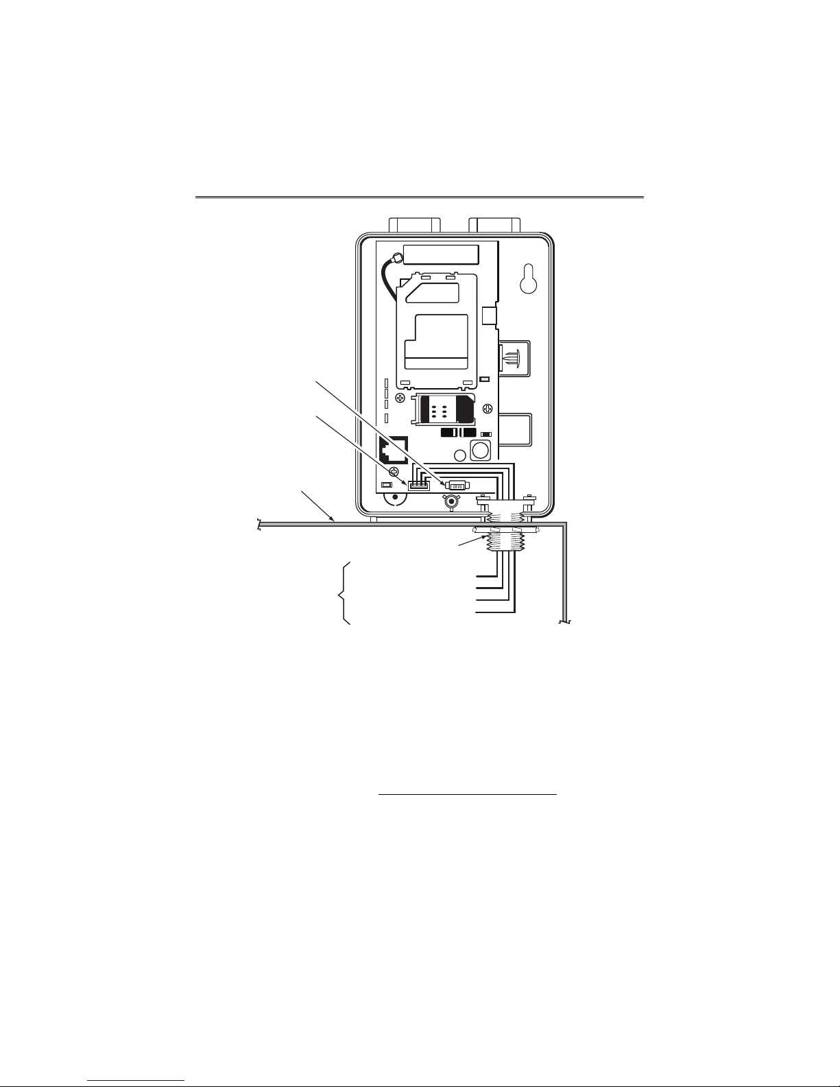
GSMX4G / GSMXCN4G Installation and Setup Guide
Audio
Connector
ECP Cable
Control Panel
Cabinet
Threaded Mount
To ECP Bus on
control panel
circuit board.
PANEL DATA OUT - Yellow
AUX PWR (+12V) - Red
GND - Black
PANEL DATA IN - Green
GSMX4G-005-V0
4. Connect the ECP cable to the communicator circuit board and thread
the wires through the threaded mounting adapter.
5. Refer to the control panel’s installation guide, and complete the ECP
cable wiring.
6. Secure the wiring with ties as necessary.
Wiring the Module for two-way voice
The GSMX4G requires an optional audio cable (GSMX-AUDIO, black) to
support two-way voice using the AVS Base Unit. Note the AVS Base
Unit is part of Honeywell’s AVS Audio Verification System
consist of the AVS Base Unit, Remote Station, and the Remote Station
PC board. For detailed information, please refer to the AVS Audio
Verification System documentation. Follow the guidelines below for
connecting the audio cable.
1. Power down the communicator, control panel and AVS Audio
Verification System. (When the communicator is fully wired up,
– 7 –
. This system
GSMX4G / GSMXCN4G Installation and Setup Guide
restore power to the communicator, control panel and AVS Audio
Verification System.)
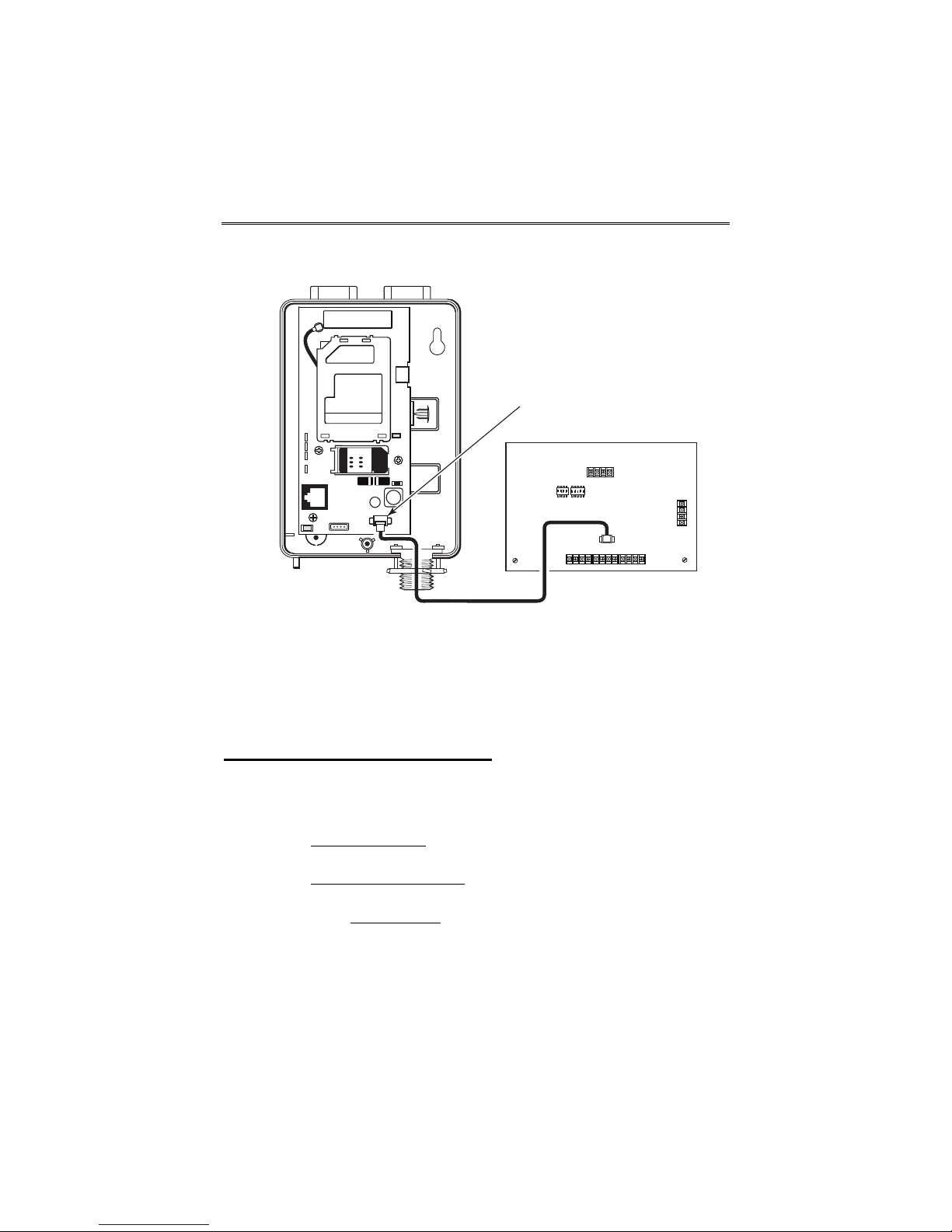
Audio
Connector
AVS BASE UNIT
ON
2341ON52341
2. Connect one end of the audio cable (5-pin connector) to the audio
connector located on the PC board in the communicator.
3. Route the audio cable to the connector on the AVS Base Unit and
connect the cable (4-pin connector).
4. Ensure the audio cable ends are secured with tie wraps to reduce
strain.
GSMX4G-011-V0
Mounting the Module on the Wall
1. Ensure control panel power (both AC and battery) is off, then remove
a suitable knockout on the top or side of the control panel cabinet.
NOTES:
• If in the wall wiring
communicator's rear wiring access hole.
• If surface mounted wiring
communicator’s bottom knockout and use that to route the wiring.
• If using two-way voice, refer to the previous topic.
2. Open the communicator’s cover. Remove the Hole Cap attached to
the plastic (trim as necessary), and snap it into the top opening of
the enclosure.
3. Secure the enclosure to the wall using both mounting holes.
will be used, route the wiring through the
will be used, remove the
– 8 –
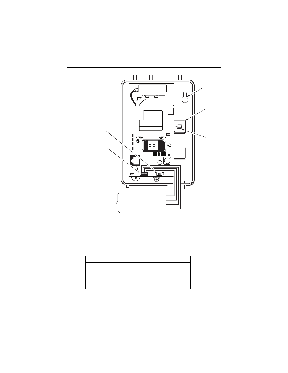
GSMX4G / GSMXCN4G Installation and Setup Guide
Mounting
Hole (2)
Wiring
Access
Hole
Audio
Connector
Hole
Cap
ECP Cable
To ECP Bus
on control panel
circuit board.
PANEL DATA OUT - Yellow
AUX PWR (+12V) - Red
GND - Black
PANEL DATA IN - Green
GSMX4G-006-V0
4. Connect the ECP cable to the communicator circuit board. When
mounting the communicator off the cabinet, the length of the supplied ECP cable will have to be spliced to a four-wire extender cable.
Ensure the splices are located within the communicator's
enclosure.
Use the table below to determine the minimum wire gauge for the
extender cable.
Minimum Wire Gauge Distance from Control Panel
#22 75 ft (23m)
#20 120 ft (37m)
#18 170 ft (52m)
#16 270 ft (82m)
5. Route the wires through the rear wiring access hole or bottom
knockout on the communicator. Continue routing the wiring to the
control panel. A control panel knockout that is presently used can be
– 9 –

GSMX4G / GSMXCN4G Installation and Setup Guide
utilized, however DO NOT utilize a control panel knockout that is
being used for primary power.
6. Refer to the installation guide for the control panel, and complete the
ECP cable wiring.
7. Secure the wiring with ties as necessary.
Programming the Module
The GSMX4G requires an AlarmNet account. For new installations,
please obtain the account information from the central station prior to
programming.
You can program the communicator by one of the following methods:
Using the AlarmNet Direct Website
• Using the AlarmNet Direct website.
• Using the 7720P Programming Tool.
• Using the control panel's programming mode (for panels that
support this option) to access the communicator's programming.
NOTE: The prompts in this document reflect use of the 7720P Programming Tool.
To program the communicator via the website (if you are already signed up
for this service), go to: https://services.alarmnet.com/AlarmNetDirect/
If you are not signed up for this service, click on “Dealer Sign-Up" and follow
the instructions. Log in and follow the on-screen prompts. Please have the
following information available when programming the communicator:
• Primary City ID (two-digit number), obtained from your monitoring
station.
• Primary Central Station ID (two-digit number), obtained from your
monitoring station.
• Primary Subscriber ID (four-digit number), obtained from your
monitoring station.
• Communicator’s MAC ID and MAC CRC number (located on the box
and inside the communicator).
After programming is complete
, the communicator must be registered. Refer
to the Register the Module topic.
– 10 –
 Loading...