

Honeywell GSMV4G, GSMVCN4G, IGSMV4G, IGSMVCN4G Quick Installation Manual
GSMV4G / GSMVCN4G, and IGSMV4G / IGSMVCN4G GSM Communicators – Quick Installation Guide
For Online Support visit: http://www.security.honeywell.com/hsc/resources/MyWebTech/
General Information and Component Identification
Congratulations on your purchase of Hone ywell's GSMV4G or IGSMV4G communicator
(GSMVCN4G, and IGSMVCN4G in Canada). These communicators send alarms and
messages from the security system’s co ntrol panel to AlarmNet for subsequent transfer
to the central monitoring station.
In addition to alarm reporting, they provide two-way voice communications with the
central station (when used with Honeywell ’s AVS Audio Verification System
). They also
provide upload/downloading capability of Honeywell's control panel program ming data.
Refer to the
Installation and Setup Guide
for the use of these features.
NOTE: Two-way voice is not compatible with Honeywell Comm ercial Control Panels
(such as the VISTA-128/250 series).
UL / ULC Two-way voice has not been evaluated by UL / ULC.
The IGSMV4G communicator has all of the features of the GSMV4G and adds internet
connectivity. (For Canada, the GSMVCN4G and the IGSMVCN4G are designed to comply
with Canadian GSM connectivity specifications.) These co mmunicators represent the
most innovative communication technology for the secur ity industry and use
sophisticated encryption to ensure the highest level of security.
Since this guide covers both models, where d ifferences occur they will be noted. This
guide addresses a simple installation using default programming values where poss ible
and is applicable for the majority of installa tions. For detailed information on UL, ULC,
and configuration of remote services
, please refer to the appropriate
Installation and
Setup Guide
for the product. The GSMV4G and the IGSMV4G are henceforth referred to
as the communicator or communications m odule.
• The communicator requires an AlarmNet a ccount. For new installations, please
obtain the account information from the central station prior to programming.
• The communicator is for control panels tha t support GSM or IGSM communicators
and the ECP communications bus. For control panels that d o not support ECP, refer
to the appropriate installation guide to use other communicator modes.
• The control panel treats the communicator as an ECP device, so ensure to program
the control panel with the communica tor’s device address. Refer to the control
panel’s
Installation and Setup Guide
for details.
REMOTE SERVICES
Honeywell offers secure web based servic es that enable users to remotely monitor a nd
control their security system. These web s ervices enable users to; monitor and control
their security system from a website or smartphone, receiv e email notifications of
system events, and receive event confirmations.
Dealers can enroll their customers for "Rem ote Services" by using the AlarmNet Dire ct website. Once
enabled, the specific programming field s associated with these features can be programmed into the
communications device either remotely u sing the AlarmNet Direct website or local ly using the 7720P
programming tool.
Due to Honeywell's continuing effort to improve our prod ucts, your device may look slightly different than
pictured.
POWER LOADING SPECIFICATIONS
GSMV4G / GSMVCN4G: 65mA standby, 380mA active.
IGSMV4G / IGSMVCN4G: 65mA standby, 380mA active.
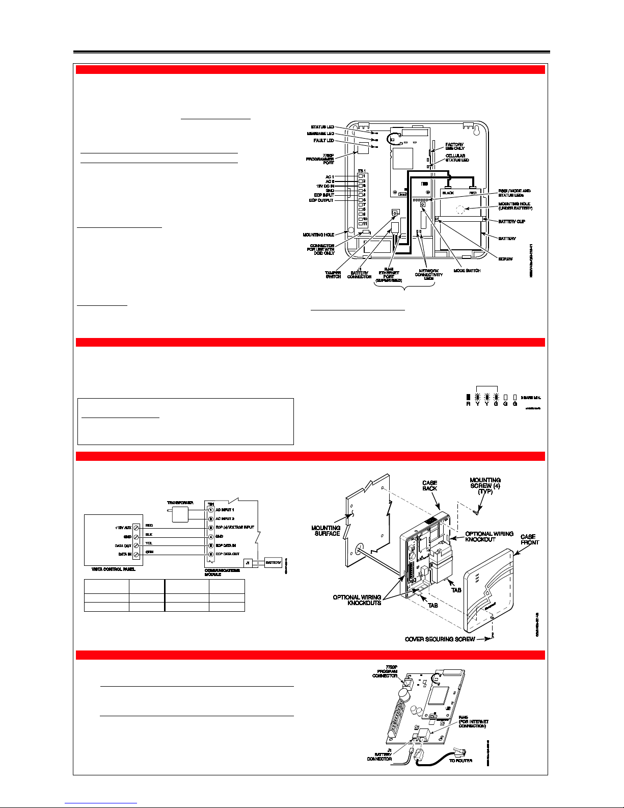
1. Determine Signal Strength and Select a Location
The communicator must be mounted indoors. When choosing a suitable mount ing location,
understand that signal strength is very important for proper operation. For most installations
using the internal antenna, mounting the unit as high as practical, and avoiding large metal
components provides adequate signal strength for proper operation.
In this step, you will use the communicator to de termine signal strength in order to find a
suitable mounting location.
Note: If the SIM is already activated, th e RSSI signal strength indicators will indi cate
signal strength. (The SIM in the GSMVCN4G and IGSMVCN4G is already activated.)
If the SIM has not been activated, the firmware in the communicator enables it to com municate with the cellular network towers ( without the SIM being activated) so that
signal strength measurements can be d etermined. In this case, you can display the
signal strength by simultaneously pre ssing the TAMPER and MODE switches.
Allow at least 60 seconds for a reading to esta blish.
Note: Read and follow the RF Exposure notice on the other side.
1. Unpack the communicator and open the case by pushing in the two bottom tabs with a
screwdriver while separating the case front.
2. Temporarily connect the AC transformer or battery to the communicator.
3. Choose the installation site with the best signal strength by
observing the signal strength (RSSI) bar graph. Signal
strength should be within 3-5 bars. The best signal strength is
usually found at the highest point in the building, near a
window.
4. Mark the location for the communicator.
2. Mount and Wire the Communicator
1. Locate the case back over the selected mounting position such that the opening in the case
back is aligned with the wire/cable opening on the mounting surface.
2. Pass the wires/cable through the opening in the case back, or route through the removable
side knockouts located on the back cover. Then secure the case back to the mounting
surface using four screws (supplied). Make the following connections:
Distance from
Control Panel
Minimum
Wire Gauge
Distance from
Control Panel
Minimum
Wire Gauge
75 ft (23m) #22 170 ft (52m) #18
120 ft (37m) #20 270 ft (82m) #16
3. When all wiring has been completed (including the Internet cable if use d), attach the case
front. Position the top first, then press the b ottom section until it snaps in place. Secur e
bottom using the supplied cover screw. (Required for UL i nstallations.)
4. You may power up the communicator and control panel.
3. Connect the Internet Cable (IGSMV4G / IGSMVCN4G only)
Connect one end of the Ethernet cable (Category 5) to the communicator’s RJ45 Ethernet
connector and the other end to the cable/DSL router as shown in the figure.
UL
• For UL installations, the Ethernet connec tion between the communicator and
the router cannot exceed 12 feet. Both units must be located within the
same room.
• Use a Listed cable/DSL router suited for the application.
For internet models only.
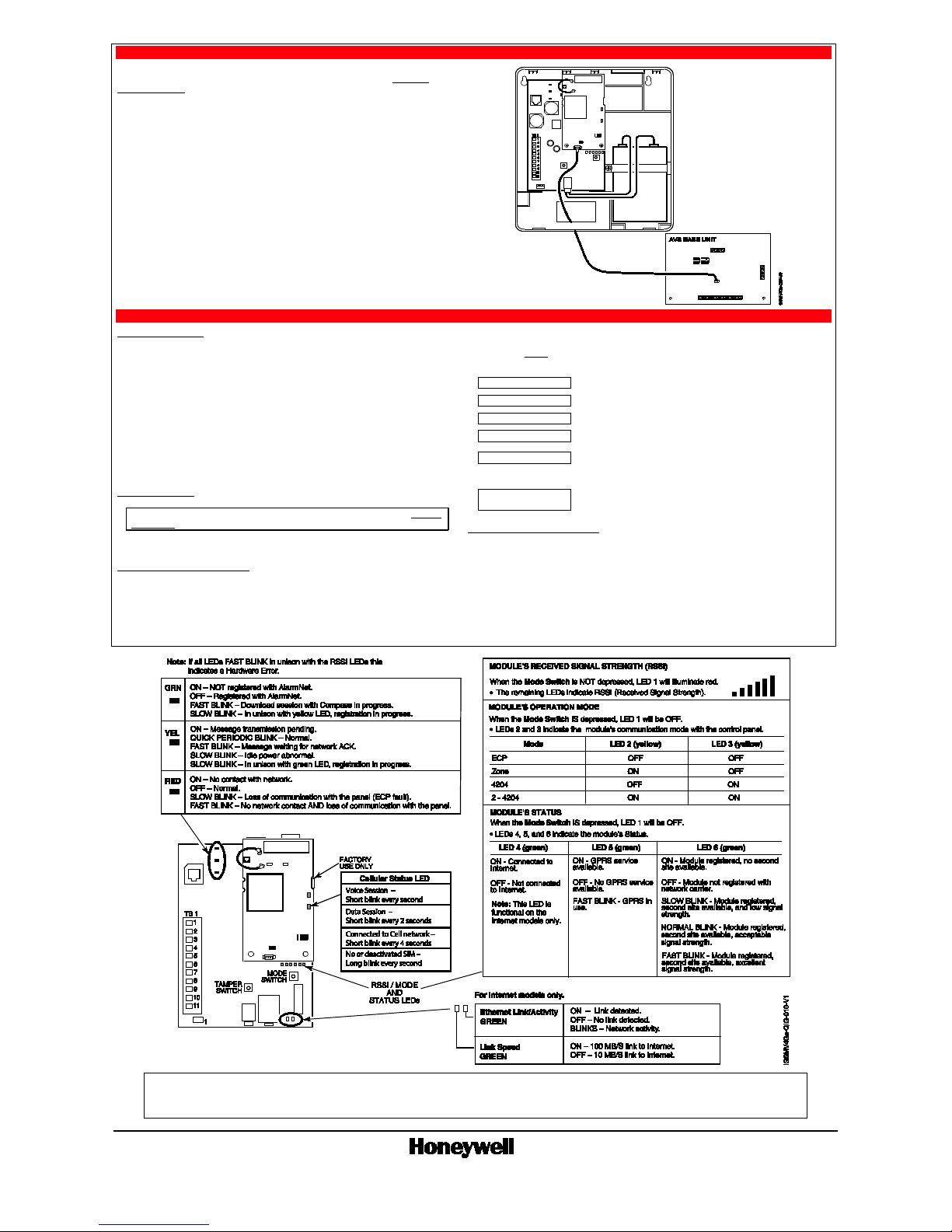
4. Connect and Route the Audio Cable for Two-way Voice (if used)
The communicator requires an optional audio cable (GSMV-AUDIO, grey) to support two-way
voice using an AVS Base Unit. Note the AVS Base Unit is part of Honeywell’s AVS Audio
Verification System. This system consist o f the AVS Base Unit, Remote Station, and the
Remote Station PC board. For detailed infor mation, please refer to the AVS Audio Ve rification
System documentation. Follow the guidelines bel ow for connecting the audio cable.
1. Power down the communicator, control panel and AVS Audio Verification System. (When
the communicator is fully wired up, resto re power to the control panel and AVS Audio
Verification System.)
2. Connect one end of the audio cable to the audio connector located on the small PC board.
3. Route the audio cable to the connector on the AVS Base Unit and connect the cable.
4. Ensure the audio cable ends are secured with tie wraps to reduce strain.
5. Setup the Account, Activate the SIM, Program, and Register the Communicator
SETUP THE ACCOUNT
To setup the customer account yo u will need to contact the central m onitoring station to get
account information, and have access to the AlarmNet Direct website. To access the AlarmNet
Direct website visit – https://services.alarmnet.com/Alarm NetDirect
If you do not wish to use the AlarmNe t Direct website, you may call AlarmNet to setup the
account; just phone 800-222-6525, then select option 1.
(Monday–Friday 8:00 am to 9:00 pm, Saturday 9:00 am to 5:30 pm EST)
Have the following information ready:
• Primary City ID (two digits),
obtained from your monitoring
station.
• Primary Subscriber ID (four digits), obtained from
your monitoring station.
• Primary Central Station ID (two
digits), obtained from your
monitoring station.
• Communicator's MAC ID, and MAC CRC number is
located on the box and inside the communicator.
ACTIVATE THE SIM
Note: The communicator comes with a SIM (Sub scriber Identity Module) that n eeds to
be activated. The GSMVCN4G and IGSMVCN4G come already activated.
To activate the SIM, log into the Ala rmNet Direct website. (Refer to the online help if needed.)
Enter the required information, then activate the SIM.
PROGRAM THE COMMUNICATOR
Using the AlarmNet Direct website:
Log in as you did to activate the SIM and comple te the communicator programming using the
“Program New Device GSM/I” tool. (Refer to the online help if needed.)
When complete you may log out of the AlarmNet Direct website.
Using the 7720 Programming Tool:
Ensure the system is powered up and connect the programming tool to the communica tor. Accept all
default settings except
the following prompts which need to be answered. Then exit the
programming mode.
Device Mode ECP
Press [#].
Primary City ID (??)
Enter number 01-99, then press [#].
Primary CS ID (??)
Enter number 01-FE, then press [#].
Primary Sub ID (????)
Enter number 0001-9999, then press [#].
Device Address (03)
Accept the default by pressing [#], or chan ge if this address
is already used.
The following prompt appears for the IGSM V4G and IGSMVCN4G only.
Notify Panel of Neither
Fault
Press [] to scroll, choose Notify Panel of Both IP&GSM
Flts, then press [#].
REGISTER THE COMMUNICATOR
Registering the communicator activates th e account with AlarmNet and enables the con trol panel to
send reports. There are three ways to register the communicator:
• You can register by logging into AlarmNet D irect choosing “Show Programmed Devices G SM/I”
tool. Search for the account using the Account Information or MAC ID. Under the “Actions”
column, use the pulldown menu select “Register” the account.
• After the communicator is installed and programmed, you can register by clicking the Tamper
Switch 3 times.
• After the communicator is installed and programmed, you can register by using the 7720P
Programming tool. Simply: Press [Shift ] th en press []. Please wait for "Registration SUCCESS"
message.
RF Exposure
Warning – The internal or external antenna(s) used with this product must be installed to provide a separation distance of at least 7.8 in. (20 cm) from all persons and must not be co-located or operating in
conjunction with any other antenna or transmitter except in accordance with FCC multi-transmitter product procedures.
Mise en Garde
Exposition aux Frequences Radio: L'antenne (s) utilisée pour cet émetteur doit être installée à une distance de séparation d'au moins 7,8 pouces (20 cm) de toutes les personnes.
Ê800-11796oŠ
800-11796 5/12 Rev. D
2 Corporate Center Drive, Suite 100, P.O. Box 9040, Melville, NY 11747
Copyright 2012 Honeywell International Inc. www.honeywell.com/security
WARRANTY
For the latest warranty information go to:
http://www.security.honeywell.com/hsc/resources/wa/
 Loading...