

Page 1
GSM-EXT Cable Assembly Installation Guide
For Documentation and Online Support: http://www.security.honeywell.com/hsc/resources/MyWebTech
General Information
The GSM-EXT cable assembly is used to connect the GSMVLP5-4G/GSMVLP5CN-4G communications module installed in
the LYNX Touch or QuickConnect Touch Series control to the AlarmNet GSM-ANT external antenna assembly.
ALARMNET GSM-ANT
EXTERNAL ANTENNA
AlarmNet GSM-ANT External Antenna & GSM-EXT Cable
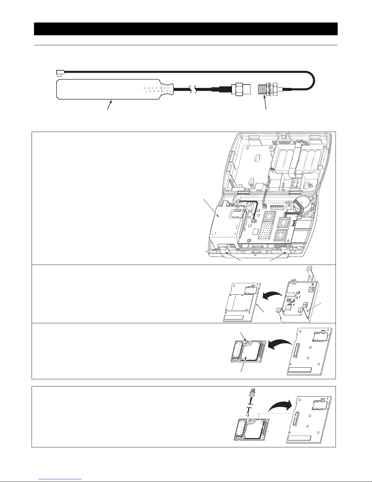
Remove the GSMVLP5-4G
1. Unplug the power supply from the wall outlet, and open
the control panel cover.
2. Release the front case from the back case by
depressing the two locking tabs at the top of the unit with
the blade of a medium size screwdriver.
3. Disconnect the battery connector from the receptacle on
the PC board.
Note: Proceed to step 4 if a communications module is
already installed in the control. If this is a new
installation, proceed to step 6.
4. Remove three screws that secure the GSMVLP54G/GSMVLP5CN-4G to the control.
5. Remove the GSMVLP5-4G/GSMVLP5CN-4G from the
LYNX Touch.
6. Flip the GSMVLP5-4G/GSMVLP5CN-4G over and
remove two screws that secure the circuit board to the
plastic housing.
7. Remove the circuit board from the GSMVLP54G/GSMVLP5CN-4G plastic housing.
8. Flip the circuit board over and carefully remove the PH8
Wireless Module. Take care to avoid damaging the
connector pins.
9. Disconnect the existing antenna cable from the PH8
Wireless Module and the circuit board and discard.
GSMVLP5-4G/
GSMVLP5CN-4G
SCREW
(3)
LOCKING TABS
ANTENNA
RECEPTACLE
GSM-EXT
CABLE
ROTATE 180
GSMVLP5-4G
CIRCUIT
BOARD
ROTATE 180
o
GSM-EXT-010-V0
o
GSM-EXT-005-V0
SCREWS
(2)
GSM-EXT-008-V0
Installing the GSM-EXT Cable
1. Connect the GSM-EXT cable to the receptacle on the
PH8 Wireless Module as shown.
2. Flip the PH8 Wireless Module over and reconnect it to
the GSMVLP5-4G/GSMVLP5CN-4G circuit board as
shown.
PH8
WIRELESS MODULE
ROTATE 180
GSM-EXT-007-V0
o
GSM-EXT-006-V0
Page 2
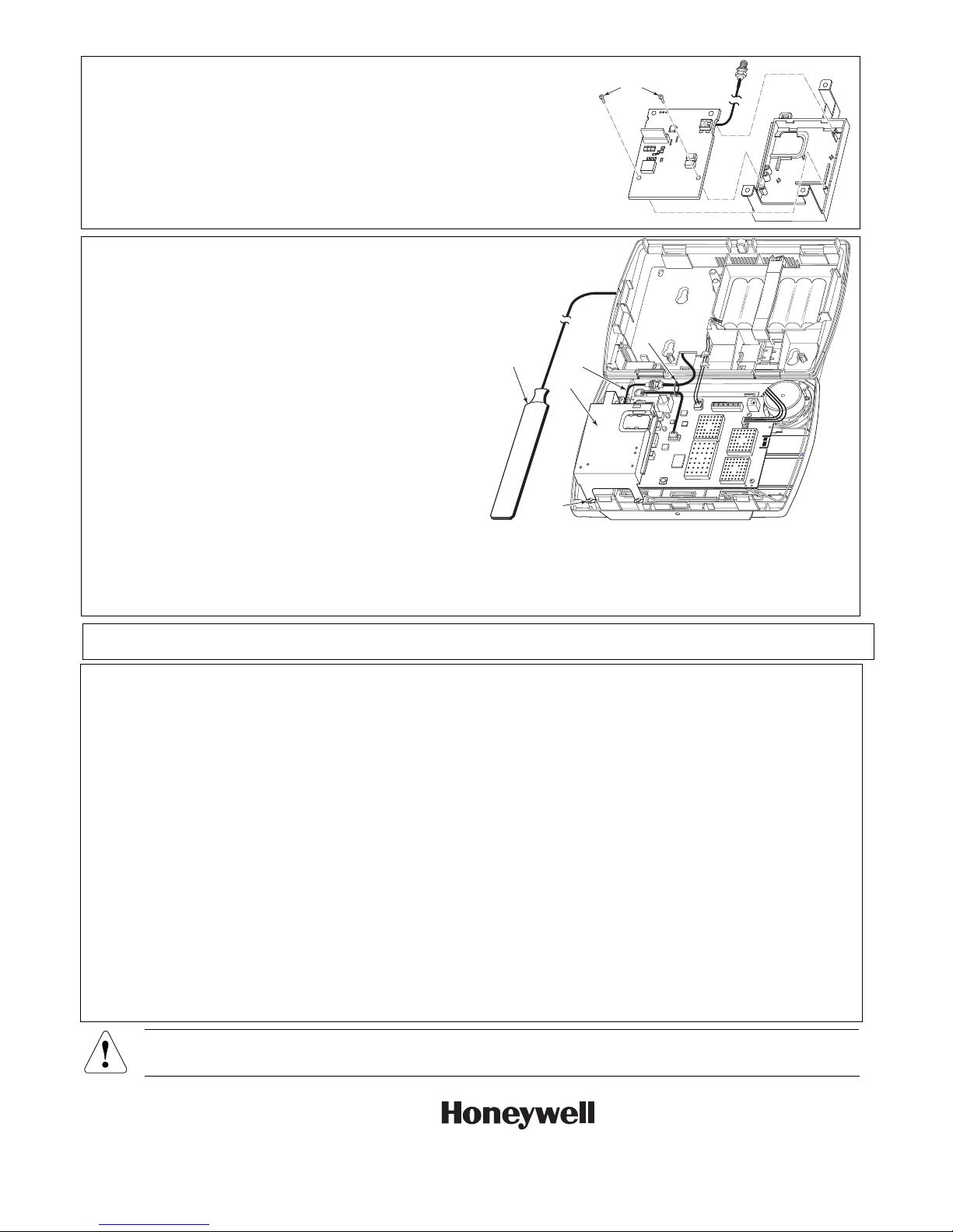
3. Flip the GSMVLP5-4G/GSMVLP5CN-4G circuit board
2 Corporate Center Drive, Suite 100
c.
over and reinstall it in the plastic housing.
4. Route the cable so it is not pinched by the plastic or
damaged by the mounting screws.
5. Install the two screws that secure the circuit board to the
plastic housing.
SCREWS
(2)
GSM-EXT-009-V0
Reinstall the GSMVLP5-4G/GSMVLP5CN-4G
1. Install the GSMVLP5-4G/GSMVLP5CN-4G in the control.
Ensure that the connector board is properly seated into
the receptacle on the control and the GSM-EXT cable is
routed properly as shown.
2. Secure the GSMVLP5-4G/GSMVLP5CN-4G in the
control with the three screws.
3. Route the external antenna cable through the control
rear case and connect the coaxial connector to the GSM-
ALARMNET
GSM-ANT
EXTERNAL
ANTENNA
GSM-EXT
CABLE
GSMVLP5-4G
TIE
WRAP
EXT cable.
4. Route the GSM-EXT cable and secure it to the tie wrap
point on the control with the provided tie wrap as shown.
5. Mount the external antenna. Refer to the Installation
Instructions provided with the AlarmNet GSM-ANT
external antenna.
6. Reconnect the battery connector to the receptacle on the
SCREW
(3)
GSM-EXT-001-V0
PC board.
7. After the wiring connection has been made, snap the
front and back case closed.
8. Plus the power supply into a 24-hour, 110VAC
unswitched outlet.
REFER TO THE INSTALLATION AND SETUP GUIDE FOR THE CONTROL WITH WHICH THIS DEVICE IS USED FOR WARRANTY
INFORMATION AND LIMITATIONS OF THE ENTIRE SYSTEM.
FEDERAL COMMUNICATIONS COMMISSION (FCC) STATEMENTS
The user shall not make any changes or modifications to the equipment unless authorized by the Installation Instructions or User's Manual. Unauthorized
changes or modifications could void the user's authority to operate the equipment.
FCC CLASS B STATEMENT
This equipment has been tested to FCC requirements and has been found acceptable for use. The FCC requires the following statement for your information:
This equipment generates and uses radio frequency energy and if not installed and used properly, that is, in strict accordance with the manufacturer's
instructions, may cause interference to radio and television reception. It has been type tested and found to comply with the limits for a Class B computing device
in accordance with the specifications in Part 15 of FCC Rules, which are designed to provide reasonable protection against such interference in a residential
installation. However, there is no guarantee that interference will not occur in a particular installation. If this equipment does cause interference to radio or
television reception, which can be determined by turning the equipment off and on, the user is encouraged to try to correct the interference by one or more of
the following measures:
• If using an indoor antenna, have a quality outdoor antenna installed.
• Reorient the receiving antenna until interference is reduced or eliminated.
• Move the radio or television receiver away from the receiver/control.
• Move the antenna leads away from any wire runs to the receiver/control.
• Plug the receiver/control into a different outlet so that it and the radio or television receiver are on different branch circuits.
• Consult the dealer or an experienced radio/TV technician for help.
INDUSTRY CANADA CLASS B STATEMENT
This Class B digital apparatus complies with Canadian ICES-003.
Cet appareil numérique de la classe B est conforme à la norme NMB-003 du Canada.
FCC / IC STATEMENT
This device complies with Part 15 of the FCC Rules, and RSS 210 of IC. Operation is subject to the following two conditions: (1) This device may not cause
harmful interference (2) This device must accept any interference received, including interference that may cause undesired operation.
Cet appareil est conforme à la partie 15 des règles de la FCC & de RSS 210 des Industries Canada. Son fonctionnement est soumis aux conditions suivantes:
(1) Cet appareil ne doit pas causer d' interferences nuisibles. (2) Cet appareil doit accepter toute interference reçue y compris les interferences causant une
reception indésirable.
WARNING: The GSMVLP5-4G/GSMVLP5CN-4G mus t be installed to provide a separation distance of at least 20 cm
from all persons.
RF Exposure
Ê800-10843-Š
800-10843 1/12 Rev. A
P.O. Box 9040, Melville, NY 11747
Copyright © 2012 Honeywell International In
www.honeywell.com/security
 Loading...