

Page 1

GNS-XL
FLIGHT MANAGEMENT SYSTEM
Operator’s Manual
Global
006-08852-0000
Rev. 4 Nov/04
N
Page 2

WARNING
Prior to export of this document, review for export license requirement is
needed.
COPYRIGHT NOTICE
Copyright ©1998-2002, 2004 Honeywell International Inc.
All rights reserved.
Reproduction of this publication or any portion thereof by any means without
the express written permission of Honeywell International Inc. is prohibited.
For further information contact the Manager, Technical Publications;
Honeywell; One Technology Center; 23500 West 105th Street; Olathe,
Kansas 66061. Telephone: (913) 712-0400.
Page 3

Revision History and Instructions
Manual GNS-X
L Operator’s Manual
Revision 4, November 2004
Part Number 006-08852-0000
This revision adds descriptions of operational procedures required to fly
three kinds of SIDs.
Insert the contents of this revision packet according to the following
instructions:
Title Page Remove and Replace
Revision History Page Insert Ahead of Existing Revision History Pages
Section 3 Remove and Replace Pages 3-17 through 3-22
Back Cover Page Remove and Replace
Back Binder Insert Remove and Replace
Rev. 4
Nov/04
R-1
GNS-XL Flight Management System
Page 4

Revision History and Instructions
Manual GNS-XL Operator’s Manual
Revision 3, October, 2002
Part Number 006-08852-0000
This revision incorporates AFIS Printer Control, deletes Air Canada and calrifies SID/STAR operation.
Insert the contents of this revision packet according to the following
instructions:
Front Binder Insert Remove and Replace
Title Page Remove and Replace
Revision History Page Insert Ahead of Existing Revision History Page
Table of Contents Remove and Replace Pages v/vi and xi through
xvi
Section 3 Remove and Replace Pages 3-9 through 3-12
Insert Page 3-12a/3-12b after Page 3-12
Remove and Replace Pages 3-13 through 3-20
and Page 3-75/3-76
Section 7 Remove and Replace Pages 7-1/7-2,7-7/7-8,
7-17 through 7-22, 7-35/7-36, 7-43 through
7-66 and insert Pages 7-67 through 7-72
Back Cover Page Remove and Replace
Back Binder Insert Remove and Replace
R-1
Rev. 3
Oct/02
GNS-XL Flight Management System
Page 5

Revision History and Instructions
Manual GNS-XL Operator’s Manual
Revision 2, April, 2000
Part Number 006-08852-0000
This revision incorporates GNS-XL Software Mod 6.
Insert the contents of this revision packet according to the following
instructions:
Front Binder Insert Remove and Replace
Title Page Remove and Replace
Revision History Page Insert Ahead of Existing Revision History Page
Table of Contents Remove and Replace Pages v/vi
Section 2 Remove and Replace Pages 2-1/2-2, 2-73
through 2-76 and 2-79/2-80
Section 3 Remove and Replace Pages 3-1 through 3-4,
3-15/3-16, 3-36.1/3-36.2 and 3-109/3-110
Back Cover Page Remove and Replace
Back Binder Insert Remove and Replace
Rev. 2
Apr/00
R-1
GNS-XL Flight Management System
Page 6

Revision History and Instructions
Manual GNS-XL Operator’s Manual
Revision 1, July 1998
Part Number 006-08852-0000
This revision consists of the following:
Add Company Routes (vi, 2-2, 3.36.1, 3-36.2, I-2)
Add Dedicated DME Interface (2-57)
Add Approach Note (3-36.3)
Add Waypoint Type Identifier (2-54, 3-48, 3-49, 3-62)
Revise Procedure Turn (3-41, 3-42, 3-43, 3-44)
Remove H Hot Key (3-57, 3-58, 3-61)
Add Fuel Use Reset Function (ix, 2-48, 3-105, 3-106)
Typographic/Administrative Corrections (Front Covers, 2-1, 2-4, 2-9, 2-10,
2-11, 2-12, 2-27, 2-28, 2-79, 3-1, 3-2, 3-3, 3-4, 3-40, 3-42, 3-43, 3-45,
3-59, 3-60, 7-12, 7-15, 7-20, 7-22, 7-54, 7-55, 7-56, 7-57, 7-58, 7-59, Back
Covers)
Rev. 1
Jul/98
R-1
GNS-XL Flight Management System
Page 7

Revision History and Instructions
Manual GNS-XL Operator’s Manual
Revision 0, October 1996
Part Number 006- 08852-0000
This revision is a complete manual revision and supersedes previous revi-
sion level manuals. Superseded manuals should be discarded.
Rev. 0
Feb/96
R-1
GNS-XL Flight Management System
Page 8

Table of Contents
SECTION 1
DESCRIPTION . . . . . . . . . . . . . . . . . . . . . . . . . . . . . . . . . . . . . . . . . . . . . . . . . . .1-1
OVERVIEW . . . . . . . . . . . . . . . . . . . . . . . . . . . . . . . . . . . . . . . . . . . . . . . . . . .1-1
GENERAL TERMS . . . . . . . . . . . . . . . . . . . . . . . . . . . . . . . . . . . . . . . . . . . . . .1-3
CONTROLS AND INDICATORS . . . . . . . . . . . . . . . . . . . . . . . . . . . . . . . . . . . .1-4
ON: . . . . . . . . . . . . . . . . . . . . . . . . . . . . . . . . . . . . . . . . . . . . . . . . . . . . . . .1-4
BRIGHTNESS (BRT): . . . . . . . . . . . . . . . . . . . . . . . . . . . . . . . . . . . . . . . . .1-4
MESSAGE KEY/ANNUNCIATOR (MSG): . . . . . . . . . . . . . . . . . . . . . . . . . . .1-4
ALPHA KEYS: . . . . . . . . . . . . . . . . . . . . . . . . . . . . . . . . . . . . . . . . . . . . . . .1-5
NUMERIC KEYS: . . . . . . . . . . . . . . . . . . . . . . . . . . . . . . . . . . . . . . . . . . . .1-5
HOLD KEY: . . . . . . . . . . . . . . . . . . . . . . . . . . . . . . . . . . . . . . . . . . . . . . . . .1-5
BACK KEY: . . . . . . . . . . . . . . . . . . . . . . . . . . . . . . . . . . . . . . . . . . . . . . . . .1-6
SPACE (SP) KEY: . . . . . . . . . . . . . . . . . . . . . . . . . . . . . . . . . . . . . . . . . . . .1-6
ENTER (ENT) KEY: . . . . . . . . . . . . . . . . . . . . . . . . . . . . . . . . . . . . . . . . . . .1-6
DISPLAY SELECTOR KEYS: . . . . . . . . . . . . . . . . . . . . . . . . . . . . . . . . . . . .1-6
PREVIOUS (PRV) KEY: . . . . . . . . . . . . . . . . . . . . . . . . . . . . . . . . . . . . . . .1-7
NEXT (NXT) KEY: . . . . . . . . . . . . . . . . . . . . . . . . . . . . . . . . . . . . . . . . . . . .1-7
LINE SELECT KEYS: . . . . . . . . . . . . . . . . . . . . . . . . . . . . . . . . . . . . . . . . . .1-7
UP/DOWN KEYS: . . . . . . . . . . . . . . . . . . . . . . . . . . . . . . . . . . . . . . . . . . . .1-7
COLORS: . . . . . . . . . . . . . . . . . . . . . . . . . . . . . . . . . . . . . . . . . . . . . . . . . .1-8
SECTION 2
PAGE DISPLAY DEFINITIONS . . . . . . . . . . . . . . . . . . . . . . . . . . . . . . . . . . . . . . .2-1
PAGE DISPLAYS AT POWER-UP . . . . . . . . . . . . . . . . . . . . . . . . . . . . . . . . . .2-1
SELF TEST PAGE . . . . . . . . . . . . . . . . . . . . . . . . . . . . . . . . . . . . . . . . . . . .2-1
INITIALIZATION PAGE . . . . . . . . . . . . . . . . . . . . . . . . . . . . . . . . . . . . . . . .2-1
FLIGHT PLAN SECTION (FPL KEY) . . . . . . . . . . . . . . . . . . . . . . . . . . . . . . . . .2-2
FLIGHT PLAN PAGES . . . . . . . . . . . . . . . . . . . . . . . . . . . . . . . . . . . . . . . . .2-2
i
Rev. 0
Oct/96
GNS-XL Flight Management System
Page 9

Table of Contents
FLIGHT PLAN LIST 1/1 (Page 1 of 1) . . . . . . . . . . . . . . . . . . . . . . . . . .2-2
FLIGHT PLAN “X” 1/1 (Page 1 of 1) . . . . . . . . . . . . . . . . . . . . . . . . . . .2-3
NAVIGATION SECTION (NAV KEY) . . . . . . . . . . . . . . . . . . . . . . . . . . . . . . . .2-13
NAVIGATION PAGES . . . . . . . . . . . . . . . . . . . . . . . . . . . . . . . . . . . . . . . .2-13
NAVIGATION 1/4 (Page 1 of 4) . . . . . . . . . . . . . . . . . . . . . . . . . . . . . .2-13
NAVIGATION 2/4 (Page 2 of 4) . . . . . . . . . . . . . . . . . . . . . . . . . . . . . .2-17
NAVIGATION 3/4 (Page 3 of 4) . . . . . . . . . . . . . . . . . . . . . . . . . . . . . .2-19
NAVIGATION 4/4 (Page 4 of 4) . . . . . . . . . . . . . . . . . . . . . . . . . . . . . .2-20
VLF SUBSECTION PAGES . . . . . . . . . . . . . . . . . . . . . . . . . . . . . . . . . . . .2-21
VLF SUBSECTION 1/4 (Page 1 of 4) . . . . . . . . . . . . . . . . . . . . . . . . . .2-21
VLF SUBSECTION 2/4 (Page 2 of 4) . . . . . . . . . . . . . . . . . . . . . . . . . .2-21
VLF SUBSECTION 3/4 (Page 3 of 4) . . . . . . . . . . . . . . . . . . . . . . . . . .2-23
VLF SUBSECTION 4/4 (Page 4 of 4) . . . . . . . . . . . . . . . . . . . . . . . . . .2-24
IRS/INS SUBSECTION PAGES . . . . . . . . . . . . . . . . . . . . . . . . . . . . . . . . .2-25
IRS (or INS) SUBSECTION 1/2 (Page 1 of 2) . . . . . . . . . . . . . . . . . . .2-25
IRS SUBSECTION 2/2 (Page 2 of 2) . . . . . . . . . . . . . . . . . . . . . . . . . .2-25
VPU SUBSECTION PAGES . . . . . . . . . . . . . . . . . . . . . . . . . . . . . . . . . . . .2-26
VPU SUBSECTION 1/4 (Page 1 of 4) . . . . . . . . . . . . . . . . . . . . . . . . . .2-26
VPU SUBSECTION 2/4 (Page 2 of 4) . . . . . . . . . . . . . . . . . . . . . . . . . .2-26
VPU SUBSECTION 3/4 (Page 3 of 4) . . . . . . . . . . . . . . . . . . . . . . . . . .2-27
VPU SUBSECTION 4/4 (Page 4 of 4) . . . . . . . . . . . . . . . . . . . . . . . . . .2-28
GPS SUBSECTION PAGES . . . . . . . . . . . . . . . . . . . . . . . . . . . . . . . . . . . .2-29
GPS SUBSECTION 1/3 (Page 1 of 3) . . . . . . . . . . . . . . . . . . . . . . . . . .2-29
GPS SUBSECTION 2/3 (Page 2 of 3) . . . . . . . . . . . . . . . . . . . . . . . . . .2-29
GPS SUBSECTION 3/3 (Page 3 of 3) . . . . . . . . . . . . . . . . . . . . . . . . . .2-31
VERTICAL NAVIGATION SECTION (VNAV KEY) . . . . . . . . . . . . . . . . . . . . . .2-32
VNAV 1/3 (Page 1 of 3) - (First line) . . . . . . . . . . . . . . . . . . . . . . . . . .2-32
ii
GNS-XL Flight Management System
Rev. 0
Oct/96
Page 10

Table of Contents
VNAV MODE: (Second line) . . . . . . . . . . . . . . . . . . . . . . . . . . . . . . . .2-32
VNAV 2/3 (Page 2 of 3) - FLIGHT PLAN WayPoint . . . . . . . . . . . . . . .2-37
VNAV DATA 1/1 (Page 1 of 1) . . . . . . . . . . . . . . . . . . . . . . . . . . . . . . .2-38
VNAV WAYPOINT 1/1 (Page 1 of 1) . . . . . . . . . . . . . . . . . . . . . . . . . .2-40
AFIS SECTION (AFIS KEY) . . . . . . . . . . . . . . . . . . . . . . . . . . . . . . . . . . . . . .2-42
PLANNING SECTION (PLAN KEY) . . . . . . . . . . . . . . . . . . . . . . . . . . . . . . . .2-42
PLAN PAGES . . . . . . . . . . . . . . . . . . . . . . . . . . . . . . . . . . . . . . . . . . . . . .2-42
PLAN 1/8 (Page 1 of 8) FUEL STATUS . . . . . . . . . . . . . . . . . . . . . . . .2-42
PLAN 2/8 (Page 2 of 8) TRIP PLAN . . . . . . . . . . . . . . . . . . . . . . . . . . .2-44
PLAN 3/8 (Page 3 of 8) FUEL PLAN . . . . . . . . . . . . . . . . . . . . . . . . . .2-46
PLAN 4/8 (Page 4 of 8) FUEL FLOW . . . . . . . . . . . . . . . . . . . . . . . . . .2-47
PLAN 5/8 (Page 5 of 8) DATE/GMT . . . . . . . . . . . . . . . . . . . . . . . . . . .2-48
PLAN 6/8 (Page 6 of 8) AIRCRAFT WEIGHT . . . . . . . . . . . . . . . . . . . .2-48
PLAN 7/8 (Page 7 of 8) FDE PREDICTION . . . . . . . . . . . . . . . . . . . . . .2-49
FDE EXCLUDE SATS 1/1 (Page 1 of 1) . . . . . . . . . . . . . . . . . . . . . . . .2-50
PLAN 8/8 (Page 8 of 8) FDE COMPUTATION . . . . . . . . . . . . . . . . . . . .2-51
HEADING SECTION (HDG KEY) . . . . . . . . . . . . . . . . . . . . . . . . . . . . . . . . . .2-53
HEADING PAGE . . . . . . . . . . . . . . . . . . . . . . . . . . . . . . . . . . . . . . . . . . . .2-53
HEADING VECTOR 1/1 (Page 1 of 1) . . . . . . . . . . . . . . . . . . . . . . . . . .2-53
TUNING SECTION (TUNE KEY) . . . . . . . . . . . . . . . . . . . . . . . . . . . . . . . . . . .2-55
TUNE 1/4 (Page 1 of 4) COMM . . . . . . . . . . . . . . . . . . . . . . . . . . . . . .2-55
TUNE 2/4 (Page 2 of 4) COMM . . . . . . . . . . . . . . . . . . . . . . . . . . . . . .2-55
TUNE 3/4 (Page 3 of 4) NAV . . . . . . . . . . . . . . . . . . . . . . . . . . . . . . . .2-56
TUNE 4/4 (Page 4 of 4) XPDR/ADF . . . . . . . . . . . . . . . . . . . . . . . . . . .2-57
HOLDING PATTERN SECTION (HOLD KEY) . . . . . . . . . . . . . . . . . . . . . . . . .2-58
HOLDING PATTERN PAGE . . . . . . . . . . . . . . . . . . . . . . . . . . . . . . . . . . . .2-58
HOLDING PATTERN 1/1 (Page 1 of 1) . . . . . . . . . . . . . . . . . . . . . . . . .2-58
iii
Rev. 0
Oct/96
GNS-XL Flight Management System
Page 11

Table of Contents
POSITION FIX PAGE . . . . . . . . . . . . . . . . . . . . . . . . . . . . . . . . . . . . . . . .2-63
DIRECT TO SECTION (
DIRECT TO PAGES . . . . . . . . . . . . . . . . . . . . . . . . . . . . . . . . . . . . . . . . . .2-64
DIRECT 1/2 (Page 1 of 2) . . . . . . . . . . . . . . . . . . . . . . . . . . . . . . . . . .2-64
WAYPOINT SECTION . . . . . . . . . . . . . . . . . . . . . . . . . . . . . . . . . . . . . . . . . .2-65
WAYPOINT PAGES . . . . . . . . . . . . . . . . . . . . . . . . . . . . . . . . . . . . . . . . .2-65
DATABASE WPT 1/1 (Page 1 of 1) . . . . . . . . . . . . . . . . . . . . . . . . . . .2-65
SPECIAL DATABASE WAYPOINTS . . . . . . . . . . . . . . . . . . . . . . . . . . . . . .2-69
PILOT ENTERED WPT (Personalized) Waypoint . . . . . . . . . . . . . . . . .2-69
OFFSET WAYPOINT . . . . . . . . . . . . . . . . . . . . . . . . . . . . . . . . . . . . . . .2-70
SPECIAL WAYPOINTS . . . . . . . . . . . . . . . . . . . . . . . . . . . . . . . . . . . . .2-71
OCEANIC REPORTING WAYPOINTS . . . . . . . . . . . . . . . . . . . . . . . . . . . .2-72
MESSAGES (MSG Key) . . . . . . . . . . . . . . . . . . . . . . . . . . . . . . . . . . . . . . . .2-73
SYSTEM MESSAGES . . . . . . . . . . . . . . . . . . . . . . . . . . . . . . . . . . . . . . . .2-74
ACTION REQUIRED: . . . . . . . . . . . . . . . . . . . . . . . . . . . . . . . . . . . . . .2-74
ADVISORY: . . . . . . . . . . . . . . . . . . . . . . . . . . . . . . . . . . . . . . . . . . . . .2-75
SENSOR MESSAGES . . . . . . . . . . . . . . . . . . . . . . . . . . . . . . . . . . . . . . . .2-78
d KEY) . . . . . . . . . . . . . . . . . . . . . . . . . . . . . . . . . .2-64
SECTION 3
SYSTEM OPERATION . . . . . . . . . . . . . . . . . . . . . . . . . . . . . . . . . . . . . . . . . . . . .3-1
PRE-DEPARTURE . . . . . . . . . . . . . . . . . . . . . . . . . . . . . . . . . . . . . . . . . . . . . .3-1
POWER ON/OFF AND PARALLAX ADJUSTMENT . . . . . . . . . . . . . . . . . . . .3-1
INITIALIZATION PAGE . . . . . . . . . . . . . . . . . . . . . . . . . . . . . . . . . . . . . . . .3-2
DATE and GMT . . . . . . . . . . . . . . . . . . . . . . . . . . . . . . . . . . . . . . . . . . . . .3-2
INITIALIZATION POSITION . . . . . . . . . . . . . . . . . . . . . . . . . . . . . . . . . . . .3-3
Option 1: Using the IDENT field for non-IRS equipped systems . . . . . .3-3
Option 2: Using the POS field . . . . . . . . . . . . . . . . . . . . . . . . . . . . . . . .3-5
BUILDING FLIGHT PLANS (FPL) . . . . . . . . . . . . . . . . . . . . . . . . . . . . . . . . . .3-7
iv
GNS-XL Flight Management System
Rev. 0
Oct/96
Page 12

Table of Contents
CREATING A FLIGHT PLAN . . . . . . . . . . . . . . . . . . . . . . . . . . . . . . . . . . . .3-7
To Delete a Waypoint . . . . . . . . . . . . . . . . . . . . . . . . . . . . . . . . . . . . . .3-8
MODIFYING A FLIGHT PLAN . . . . . . . . . . . . . . . . . . . . . . . . . . . . . . . . . . .3-8
To Access The Desired Flight Plan: . . . . . . . . . . . . . . . . . . . . . . . . . . . .3-8
Deleting A Waypoint: . . . . . . . . . . . . . . . . . . . . . . . . . . . . . . . . . . . . . . .3-9
ADDING A WAYPOINT . . . . . . . . . . . . . . . . . . . . . . . . . . . . . . . . . . . . . . . .3-9
ADDING OCEANIC WAYPOINTS . . . . . . . . . . . . . . . . . . . . . . . . . . . . . . .3-10
USING DUPLICATE WAYPOINT IDENTIFIERS . . . . . . . . . . . . . . . . . . . . .3-11
REVIEWING WAYPOINT DATA/COORDINATES . . . . . . . . . . . . . . . . . . . .3-12
To Access The Desired Flight Plan: . . . . . . . . . . . . . . . . . . . . . . . . . .3-12a
ERASING A STORED FLIGHT PLAN . . . . . . . . . . . . . . . . . . . . . . . . . . . . .3-12
FLIGHT PLAN (FPL) SELECTION . . . . . . . . . . . . . . . . . . . . . . . . . . . . . . . . .3-13
INITIAL LEG SELECTION . . . . . . . . . . . . . . . . . . . . . . . . . . . . . . . . . . . . .3-14
BEFORE TAXI (IRS EQUIPPED) . . . . . . . . . . . . . . . . . . . . . . . . . . . . . . . .3-15
RUNWAY LINE-UP (IRS EQUIPPED) . . . . . . . . . . . . . . . . . . . . . . . . . . . . . .3-15
IRS, VLF (RPU), GPS AND/OR VPU EQUIPPED . . . . . . . . . . . . . . . . . . . .3-15
VLF (RPU) AND/OR VPU EQUIPPED ONLY . . . . . . . . . . . . . . . . . . . . . . .3-15
SIDs, STARs, APPROACHES AND ENROUTE AIRWAYS . . . . . . . . . . . . .3-16
ENTERING A SID ON THE ACTIVE FPL . . . . . . . . . . . . . . . . . . . . . . . . . .3-18
REVIEWING A SID FROM ANY STORED FPL OR THE ACTIVE FPL PAGE 3-20
EDITING A SID FROM ANY STORED FPL OR THE ACTIVE FPL PAGE . . .3-21
ERASING A SID FROM ANY STORED FPL OR THE ACTIVE FPL PAGE . .3-22
ADDING OR DELETING WAYPOINTS WITHIN A SID . . . . . . . . . . . . . . . .3-23
To Delete a Waypoint . . . . . . . . . . . . . . . . . . . . . . . . . . . . . . . . . . . . . .3-23
ENTERING AN AIRWAY FROM ANY STORED FPL
OR THE ACTIVE FPL PAGE . . . . . . . . . . . . . . . . . . . . . . . . . . . . . . . . . . .3-24
Option 1 . . . . . . . . . . . . . . . . . . . . . . . . . . . . . . . . . . . . . . . . . . . . . . . .3-24
Option 2 . . . . . . . . . . . . . . . . . . . . . . . . . . . . . . . . . . . . . . . . . . . . . . .3-25
v
Rev. 3
Oct/02
GNS-XL Flight Management System
Page 13

Table of Contents
EDITING AN AIRWAY . . . . . . . . . . . . . . . . . . . . . . . . . . . . . . . . . . . . . . . .3-26
ENTERING A STAR OR PROFILE DESCENT ON ANY STORED FPL
OR THE ACTIVE FPL PAGE . . . . . . . . . . . . . . . . . . . . . . . . . . . . . . . . . . .3-27
REVIEWING A STAR FROM A STORED FPL OR THE ACTIVE FPL PAGE .3-29
EDITING A STAR FROM A STORED FPL OR THE ACTIVE FPL PAGE . . . .3-29
ERASING A STAR FROM A STORED FPL OR THE ACTIVE FPL PAGE . . .3-30
ADDING WAYPOINTS WITHIN A STAR . . . . . . . . . . . . . . . . . . . . . . . . . .3-31
DELETING WAYPOINTS OF A STAR . . . . . . . . . . . . . . . . . . . . . . . . . . . .3-31
ENTERING AN APPROACH ON A STORED FPL
OR THE ACTIVE FPL PAGE . . . . . . . . . . . . . . . . . . . . . . . . . . . . . . . . . . .3-32
REVIEWING AN APPROACH FROM A STORED FPL
OR THE ACTIVE FPL PAGE . . . . . . . . . . . . . . . . . . . . . . . . . . . . . . . . . . .3-34
EDITING AN APPROACH FROM A STORED FPL
OR THE ACTIVE FPL PAGE . . . . . . . . . . . . . . . . . . . . . . . . . . . . . . . . . . .3-34
ERASING AN APPROACH FROM A STORED FPL
OR THE ACTIVE FPL . . . . . . . . . . . . . . . . . . . . . . . . . . . . . . . . . . . . . . . .3-35
DELETING AN APPROACH WAYPOINT . . . . . . . . . . . . . . . . . . . . . . . . . .3-36
USING A STAR AND AN APPROACH IN THE SAME FLIGHT PLAN . . . . .3-36
SELECTING A COMPANY ROUTE AND ADDING IT TO THE
ACTIVE FLIGHT PLAN . . . . . . . . . . . . . . . . . . . . . . . . . . . . . . . . . . . . . .3-36.1
EXECUTING APPROACHES . . . . . . . . . . . . . . . . . . . . . . . . . . . . . . . . . . . . .3-37
LOADING A GPS/GPS OVERLAY APPROACH . . . . . . . . . . . . . . . . . . . . .3-38
EXECUTING A GPS/GPS OVERLAY APPROACH . . . . . . . . . . . . . . . . . . .3-39
Using Radar Vectors to FINAL APPROACH COURSE . . . . . . . . . . . . . .3-39
After receiving the final intercept vector from ATC: . . . . . . . . . . . . . . .3-40
USING OWN NAVIGATION - NO DME ARC . . . . . . . . . . . . . . . . . . . . .3-41
PROCEDURE TURN . . . . . . . . . . . . . . . . . . . . . . . . . . . . . . . . . . . . . . . . .3-41
USING RADAR VECTORS TO INTERCEPT A DME ARC . . . . . . . . . . . . . .3-44
ENROUTE . . . . . . . . . . . . . . . . . . . . . . . . . . . . . . . . . . . . . . . . . . . . . . . . . . .3-51
DIRECT TO - ACTIVE FLIGHT PLAN WAYPOINT . . . . . . . . . . . . . . . . . . .3-51
DIRECT TO - HP WAYPOINT . . . . . . . . . . . . . . . . . . . . . . . . . . . . . . . . . .3-52
vi
GNS-XL Flight Management System
Rev. 1
Jul/98
Page 14

Table of Contents
To Select and Go Direct To HP Waypoint: . . . . . . . . . . . . . . . . . . . . . .3-52
To Cancel Holding Pattern:(from the Holding Pattern page) . . . . . . . .3-52
DIRECT TO - RANDOM WAYPOINT . . . . . . . . . . . . . . . . . . . . . . . . . . . . .3-53
DIRECT TO - CLOSEST AIRPORT . . . . . . . . . . . . . . . . . . . . . . . . . . . . . .3-54
PSEUDO-VORTAC (SELECTED COURSE) . . . . . . . . . . . . . . . . . . . . . . . .3-55
USING HEADING VECTOR . . . . . . . . . . . . . . . . . . . . . . . . . . . . . . . . . . . . . .3-57
PROGRAMMING A HEADING VECTOR . . . . . . . . . . . . . . . . . . . . . . . . . .3-57
CHANGING HEADING VECTOR WHILE IN HEADING SELECT MODE . . . .3-58
CHANGING TO WAYPOINT WHILE IN HEADING SELECT MODE . . . . . . .3-58
CANCELING HEADING SELECT MODE . . . . . . . . . . . . . . . . . . . . . . . . . . .3-59
PROGRAMMING AN INTERCEPT . . . . . . . . . . . . . . . . . . . . . . . . . . . . . . .3-59
PROGRAMMING A HEADING INTERCEPT TO THE
FINAL APPROACH COURSE . . . . . . . . . . . . . . . . . . . . . . . . . . . . . . . . . .3-61
PROGRAMMING A HOLDING PATTERN . . . . . . . . . . . . . . . . . . . . . . . . . . . .3-63
REVIEWING, EDITING, OR CANCELING A HOLDING PATTERN . . . . . . . . . .3-65
REVIEWING . . . . . . . . . . . . . . . . . . . . . . . . . . . . . . . . . . . . . . . . . . . . . . .3-65
EDITING . . . . . . . . . . . . . . . . . . . . . . . . . . . . . . . . . . . . . . . . . . . . . . . . . .3-66
CANCELING . . . . . . . . . . . . . . . . . . . . . . . . . . . . . . . . . . . . . . . . . . . . . . .3-66
EXITING A HOLDING PATTERN . . . . . . . . . . . . . . . . . . . . . . . . . . . . . . . . . .3-66
EXITING HOLDING PATTERN NEXT TIME OVER HOLDING FIX . . . . . . . .3-67
EXITING HOLDING PATTERN BY GOING DIRECT TO HOLDING FIX . . . .3-68
EXITING HOLDING PATTERN BY PERFORMING A LEG CHANGE . . . . . .3-68
VERTICAL NAVIGATION (VNAV) OPERATION - PRE-DEPARTURE . . . . . . .3-71
SETTING CRUISE ALTITUDE, TRANSITION LEVEL,
AND DEFAULT FLIGHT PATH ANGLE . . . . . . . . . . . . . . . . . . . . . . . . . . . .3-71
CREATING/CHANGING VNAV WAYPOINTS . . . . . . . . . . . . . . . . . . . . . . .3-72
To program a Path Descent . . . . . . . . . . . . . . . . . . . . . . . . . . . . . . . .3-74
REVIEWING VNAV WAYPOINTS . . . . . . . . . . . . . . . . . . . . . . . . . . . . . . .3-75
vii
Rev. 0
Oct/96
GNS-XL Flight Management System
Page 15

Table of Contents
Using Active Flight Plan Page . . . . . . . . . . . . . . . . . . . . . . . . . . . . . . .3-75
Using VNAV Flight Plan Waypoints Page . . . . . . . . . . . . . . . . . . . . . . .3-76
VERTICAL NAVIGATION - ENROUTE . . . . . . . . . . . . . . . . . . . . . . . . . . . . . .3-76
PROGRAMMING VERTICAL PATH DESCENTS . . . . . . . . . . . . . . . . . . . .3-76
Using Database (DB) FPA . . . . . . . . . . . . . . . . . . . . . . . . . . . . . . . . . .3-77
Using Default ( DEF) FPA . . . . . . . . . . . . . . . . . . . . . . . . . . . . . . . . . . .3-77
Using Manual (MAN) FPA . . . . . . . . . . . . . . . . . . . . . . . . . . . . . . . . . .3-77
Using Automatic (AUTO) FPA . . . . . . . . . . . . . . . . . . . . . . . . . . . . . . .3-78
EDITING ALTITUDE CONSTRAINTS . . . . . . . . . . . . . . . . . . . . . . . . . . . . .3-79
Option 1: Using VNAV Page . . . . . . . . . . . . . . . . . . . . . . . . . . . . . . . . .3-79
Option 2: Using VNAV FPL WAYPOINT Page . . . . . . . . . . . . . . . . . . . .3-79
Option 3: Using the VNAV WAYPOINT Page . . . . . . . . . . . . . . . . . . . .3-80
DIRECT TO - VNAV WAYPOINT AS LATERAL WAYPOINT . . . . . . . . . . . .3-81
DIRECT TO - VNAV WAYPOINT . . . . . . . . . . . . . . . . . . . . . . . . . . . . . . . .3-83
CREATING VNAV PROFILE WAYPOINTS . . . . . . . . . . . . . . . . . . . . . . . . .3-84
Top of Climb (#TOC) . . . . . . . . . . . . . . . . . . . . . . . . . . . . . . . . . . . . . .3-84
Top of Descent (#TOD) . . . . . . . . . . . . . . . . . . . . . . . . . . . . . . . . . . . .3-85
Pre-Selected Altitude Intercept Point (#PRESL) . . . . . . . . . . . . . . . . .3-86
Descent Reference Waypoints . . . . . . . . . . . . . . . . . . . . . . . . . . . . . . .3-86
REMOTE TUNING . . . . . . . . . . . . . . . . . . . . . . . . . . . . . . . . . . . . . . . . . . . . . . .3-89
TUNING COMMS . . . . . . . . . . . . . . . . . . . . . . . . . . . . . . . . . . . . . . . . . . . . .3-89
TUNING NAVs . . . . . . . . . . . . . . . . . . . . . . . . . . . . . . . . . . . . . . . . . . . . .3-90
Keyboard Method . . . . . . . . . . . . . . . . . . . . . . . . . . . . . . . . . . . . . . . .3-90
TRANSPONDER AND ADF KEYBOARD TUNE . . . . . . . . . . . . . . . . . . . . .3-93
PLANNING PROCEDURES . . . . . . . . . . . . . . . . . . . . . . . . . . . . . . . . . . . . . .3-95
FUEL PLANNING . . . . . . . . . . . . . . . . . . . . . . . . . . . . . . . . . . . . . . . . . . .3-95
TRIP PLANNING . . . . . . . . . . . . . . . . . . . . . . . . . . . . . . . . . . . . . . . . . . .3-96
viii
GNS-XL Flight Management System
Rev. 0
Oct/96
Page 16

Table of Contents
To Enter Manual Groundspeed: . . . . . . . . . . . . . . . . . . . . . . . . . . . . . .3-98
To Return to Automatic Groundspeed: . . . . . . . . . . . . . . . . . . . . . . . .3-98
To update the TRIP PLAN leg to the current TO waypoint
with an Active Flight Plan selected: . . . . . . . . . . . . . . . . . . . . . . . . . .3-100
FLIGHT PLAN FUEL PLANNING . . . . . . . . . . . . . . . . . . . . . . . . . . . . . . .3-100
To Enter Manual Groundspeed: . . . . . . . . . . . . . . . . . . . . . . . . . . . . .3-102
To Return To Automatic Groundspeed: . . . . . . . . . . . . . . . . . . . . . . .3-102
To Enter A Manual Fuel Flow: . . . . . . . . . . . . . . . . . . . . . . . . . . . . . .3-102
To Return to Automatic Fuel Flow: . . . . . . . . . . . . . . . . . . . . . . . . . .3-102
VERIFYING OR CHANGING DATE AND TIME . . . . . . . . . . . . . . . . . . . . .3-104
VERIFYING OR CHANGING AIRCRAFT WEIGHT PARAMETERS . . . . . .3-105
RESETTING FUEL USED . . . . . . . . . . . . . . . . . . . . . . . . . . . . . . . . . . . .3-106
SPECIAL PROCEDURES . . . . . . . . . . . . . . . . . . . . . . . . . . . . . . . . . . . . . . .3-107
PILOT ENTERED LEG CHANGE . . . . . . . . . . . . . . . . . . . . . . . . . . . . . . .3-107
PREVENTING AUTOMATIC LEG CHANGES . . . . . . . . . . . . . . . . . . . . . .3-109
DEAD RECKONING (DR) TO PRIMARY NAVIGATION MODE -
VLF (RPU) ONLY EQUIPPED . . . . . . . . . . . . . . . . . . . . . . . . . . . . . . . . .3-110
POSITION CHECK AND UPDATE PROCEDURES . . . . . . . . . . . . . . . . . .3-110
Using a Sensor . . . . . . . . . . . . . . . . . . . . . . . . . . . . . . . . . . . . . . . . .3-110
Over Known Point . . . . . . . . . . . . . . . . . . . . . . . . . . . . . . . . . . . . . . .3-111
Using An Offset . . . . . . . . . . . . . . . . . . . . . . . . . . . . . . . . . . . . . . . . .3-112
PARALLEL COURSE . . . . . . . . . . . . . . . . . . . . . . . . . . . . . . . . . . . . . . .3-114
MANUAL MAGNETIC VARIATION ENTRY . . . . . . . . . . . . . . . . . . . . . . .3-115
RETURNING TO AUTOMATIC VARIATION . . . . . . . . . . . . . . . . . . . . . . . . .3-115
SELECTING ETE, ETA, DIS, OR ALT DISPLAY OPTION . . . . . . . . . . . . .3-115
SELECTING NAV PAGE ETA OR ALT DISPLAY OPTION . . . . . . . . . . . .3-116
INITIALIZATION ENROUTE VLF (RPU) ONLY . . . . . . . . . . . . . . . . . . . .3-117
Position Update: . . . . . . . . . . . . . . . . . . . . . . . . . . . . . . . . . . . . . . . .3-118
MANUAL TAS ENTRY only VLF is available . . . . . . . . . . . . . . . . . . . . . .3-118
ix
Rev. 1
Jul/98
GNS-XL Flight Management System
Page 17

Table of Contents
MANUAL HEADING ENTRY only if IRS or VLF is available . . . . . . . . . . .3-119
VLF/OMEGA STATION DESELECTION . . . . . . . . . . . . . . . . . . . . . . . . . .3-120
SENSOR DESELECTION . . . . . . . . . . . . . . . . . . . . . . . . . . . . . . . . . . . . .3-121
EXTERNAL WAYPOINT ACCEPTANCE . . . . . . . . . . . . . . . . . . . . . . . . . .3-122
PRESENT POSITION AS A WAYPOINT . . . . . . . . . . . . . . . . . . . . . . . . .3-123
TRUE HEADING . . . . . . . . . . . . . . . . . . . . . . . . . . . . . . . . . . . . . . . . . . .3-124
Aircraft Equipped With TRUE/MAG Switch . . . . . . . . . . . . . . . . . . . .3-124
Aircraft Not Equipped With A TRUE/MAG Switch . . . . . . . . . . . . . . .3-125
SET HEADING ENTRY . . . . . . . . . . . . . . . . . . . . . . . . . . . . . . . . . . . . . .3-125
LOSS OF POWER IN FLIGHT . . . . . . . . . . . . . . . . . . . . . . . . . . . . . . . . .3-126
CREATING/CHANGING PILOT ENTERED
(PERSONALIZED) WAYPOINTS . . . . . . . . . . . . . . . . . . . . . . . . . . . . . . .3-127
Creating Pilot Entered (Personalized) Waypoints: . . . . . . . . . . . . . .3-128
Changing Pilot Entered (Personalized) Waypoints: . . . . . . . . . . . . . .3-128
CREATING AN OFFSET WAYPOINT . . . . . . . . . . . . . . . . . . . . . . . . . . . .3-129
PERFORMING FDE PREDICTION FOR OCEANIC/REMOTE OPERATION .3-130
SECTION 4
VLF/OMEGA TRANSMITTER SITES . . . . . . . . . . . . . . . . . . . . . . . . . . . . . . . . . .4-1
VLF COMMUNICATIONS STATIONS . . . . . . . . . . . . . . . . . . . . . . . . . . . . . . . .4-1
OMEGA NAVIGATIONAL NETWORK . . . . . . . . . . . . . . . . . . . . . . . . . . . . . . . .4-1
OMEGA NAVIGATIONAL NETWORK (Continued) . . . . . . . . . . . . . . . . . . . . . .4-2
SECTION 5
DATABASE UPDATE . . . . . . . . . . . . . . . . . . . . . . . . . . . . . . . . . . . . . . . . . . . . . .5-1
DATA BASE UPDATE PROCEDURES . . . . . . . . . . . . . . . . . . . . . . . . . . . . . . .5-1
TO UPDATE . . . . . . . . . . . . . . . . . . . . . . . . . . . . . . . . . . . . . . . . . . . . . . . .5-1
WHEN UPDATE IS COMPLETE . . . . . . . . . . . . . . . . . . . . . . . . . . . . . . . . . .5-2
IF UPDATE FAILS . . . . . . . . . . . . . . . . . . . . . . . . . . . . . . . . . . . . . . . . . . . .5-2
x
GNS-XL Flight Management System
Rev. 0
Oct/96
Page 18

Table of Contents
SECTION 6
LIST OF ABBREVIATIONS AND DEFINITIONS . . . . . . . . . . . . . . . . . . . . . . . . . . .6-1
SECTION 7
DESCRIPTION . . . . . . . . . . . . . . . . . . . . . . . . . . . . . . . . . . . . . . . . . . . . . . . .7-1
Global Data Center (GDC) . . . . . . . . . . . . . . . . . . . . . . . . . . . . . . . . . . . . .7-2
Data Transfer Unit (DTU) . . . . . . . . . . . . . . . . . . . . . . . . . . . . . . . . . . . . . .7-2
Data Management Unit (DMU) . . . . . . . . . . . . . . . . . . . . . . . . . . . . . . . . . .7-2
Antenna Switching Unit (ASU) . . . . . . . . . . . . . . . . . . . . . . . . . . . . . . . . . .7-2
Satellite Communications Unit (SCU) . . . . . . . . . . . . . . . . . . . . . . . . . . . .7-3
High Power Amplifier/ Low Noise Amplifier (HPA/LNA) . . . . . . . . . . . . . . .7-3
Satellite Antenna . . . . . . . . . . . . . . . . . . . . . . . . . . . . . . . . . . . . . . . . . . . .7-3
PAGE DISPLAY DEFINITIONS . . . . . . . . . . . . . . . . . . . . . . . . . . . . . . . . . . . .7-3
AFIS Flight Plan List Page . . . . . . . . . . . . . . . . . . . . . . . . . . . . . . . . . . . . .7-3
Flight Plan Progress (NAVIGATION Page 5) . . . . . . . . . . . . . . . . . . . . . . .7-4
AFIS Menu Page . . . . . . . . . . . . . . . . . . . . . . . . . . . . . . . . . . . . . . . . . . . .7-6
AFIS FLT PLAN Pages . . . . . . . . . . . . . . . . . . . . . . . . . . . . . . . . . . . . . . . .7-7
AFIS FLT PLAN Page 1 . . . . . . . . . . . . . . . . . . . . . . . . . . . . . . . . . . . . . . . .7-7
Fuel and Time Requirements . . . . . . . . . . . . . . . . . . . . . . . . . . . . . . . . .7-7
AFIS FLT PLAN Page 2 . . . . . . . . . . . . . . . . . . . . . . . . . . . . . . . . . . . . . . . .7-9
Weights, Flight Level and Route . . . . . . . . . . . . . . . . . . . . . . . . . . . . . .7-9
AFIS FLT PLAN Page 3 . . . . . . . . . . . . . . . . . . . . . . . . . . . . . . . . . . . . . . .7-10
Operator Inputs . . . . . . . . . . . . . . . . . . . . . . . . . . . . . . . . . . . . . . . . . .7-10
AFIS FLT PLAN Page 4 . . . . . . . . . . . . . . . . . . . . . . . . . . . . . . . . . . . . . . .7-11
Performance Bias . . . . . . . . . . . . . . . . . . . . . . . . . . . . . . . . . . . . . . . .7-11
SIGMETS Pages . . . . . . . . . . . . . . . . . . . . . . . . . . . . . . . . . . . . . . . . . . . .7-11
TERMINAL WEATHER Pages . . . . . . . . . . . . . . . . . . . . . . . . . . . . . . . . . .7-12
TERMINAL WX DATA Pages . . . . . . . . . . . . . . . . . . . . . . . . . . . . . . . . . .7-13
xi
Rev. 0
Oct/96
GNS-XL Flight Management System
Page 19

Table of Contents
WINDS ALOFT Pages . . . . . . . . . . . . . . . . . . . . . . . . . . . . . . . . . . . . . . . .7-13
WINDS ALOFT Data Pages . . . . . . . . . . . . . . . . . . . . . . . . . . . . . . . . . . . .7-13
RECALL AFIS FPL Page . . . . . . . . . . . . . . . . . . . . . . . . . . . . . . . . . . . . . .7-14
SEND AFIS MESSAGE Page . . . . . . . . . . . . . . . . . . . . . . . . . . . . . . . . . . .7-15
PPM MENU Page (Preprogrammed Messages) . . . . . . . . . . . . . . . . . . . .7-17
PREPROGRAMMED MESSAGE Pages . . . . . . . . . . . . . . . . . . . . . . . . . . .7-17
DISPLAY AFIS MSG Page . . . . . . . . . . . . . . . . . . . . . . . . . . . . . . . . . . . .7-18
OPERATING MODES Page (For AFIS Users Equipped with
Satellite Data Communications System) . . . . . . . . . . . . . . . . . . . . . . . . .7-18
AUTO REPORT: . . . . . . . . . . . . . . . . . . . . . . . . . . . . . . . . . . . . . . . . . .7-18
AUTO WX UPDT (weather update): . . . . . . . . . . . . . . . . . . . . . . . . . . .7-18
VHF LINK CONTROL Page . . . . . . . . . . . . . . . . . . . . . . . . . . . . . . . . . .7-20
SAT LINK CONTROL Page . . . . . . . . . . . . . . . . . . . . . . . . . . . . . . . . . .7-20
OPERATING MODES Page (For AFIS Users NOT Equipped with
Satellite Data Communications System) . . . . . . . . . . . . . . . . . . . . . . . . .7-21
AUTO REPORT: . . . . . . . . . . . . . . . . . . . . . . . . . . . . . . . . . . . . . . . . . .7-21
AUTO WX UPDT (weather update): . . . . . . . . . . . . . . . . . . . . . . . . . . .7-22
Active Flight Plan Page (for AFIS Flight Plan Updating) . . . . . . . . . . . . . .7-23
AFIS UPDATE Verification Page . . . . . . . . . . . . . . . . . . . . . . . . . . . . . . . .7-23
SYSTEM MESSAGES Page . . . . . . . . . . . . . . . . . . . . . . . . . . . . . . . . . . .7-24
SYSTEM MESSAGES . . . . . . . . . . . . . . . . . . . . . . . . . . . . . . . . . . . . . . . .7-24
ADVISORY: . . . . . . . . . . . . . . . . . . . . . . . . . . . . . . . . . . . . . . . . . . . . .7-24
SYSTEM OPERATION . . . . . . . . . . . . . . . . . . . . . . . . . . . . . . . . . . . . . . . . . .7-27
Pre-Departure . . . . . . . . . . . . . . . . . . . . . . . . . . . . . . . . . . . . . . . . . . . . . . . .7-27
AFIS Flight Plan Selection . . . . . . . . . . . . . . . . . . . . . . . . . . . . . . . . . . . .7-27
To enter an AFIS Flight Plan . . . . . . . . . . . . . . . . . . . . . . . . . . . . . . . . . . .7-27
ENROUTE . . . . . . . . . . . . . . . . . . . . . . . . . . . . . . . . . . . . . . . . . . . . . . . . .7-28
Reviewing Flight Plan Progress . . . . . . . . . . . . . . . . . . . . . . . . . . . . . . . .7-28
xii
GNS-XL Flight Management System
Rev. 3
Oct/02
Page 20

Table of Contents
Reviewing AFIS Planned Leg Data . . . . . . . . . . . . . . . . . . . . . . . . . . . . . .7-28
Reviewing AFIS Flight Plan Data . . . . . . . . . . . . . . . . . . . . . . . . . . . . . . .7-29
AFIS Flight Plan Page 1 . . . . . . . . . . . . . . . . . . . . . . . . . . . . . . . . . . . . . .7-29
AFIS Flight Plan Page 2 . . . . . . . . . . . . . . . . . . . . . . . . . . . . . . . . . . . . . .7-30
AFIS Flight Plan Page 3 . . . . . . . . . . . . . . . . . . . . . . . . . . . . . . . . . . . . . .7-31
AFIS Flight Plan Page 4 . . . . . . . . . . . . . . . . . . . . . . . . . . . . . . . . . . . . . .7-31
SIGMETS Review/update . . . . . . . . . . . . . . . . . . . . . . . . . . . . . . . . . . . . .7-32
Terminal Weather Menu - Data update and Review . . . . . . . . . . . . . . . . .7-33
To insert a new identifier: . . . . . . . . . . . . . . . . . . . . . . . . . . . . . . . . . .7-34
To delete text when there is no data entry in progress: . . . . . . . . . . . .7-34
Winds Aloft Menu - Data update and Review . . . . . . . . . . . . . . . . . . . . . .7-34
To insert a new identifier: . . . . . . . . . . . . . . . . . . . . . . . . . . . . . . . . . .7-35
To delete text when there is no data entry in progress: . . . . . . . . . . .7-36
Recalling AFIS Flight Plan . . . . . . . . . . . . . . . . . . . . . . . . . . . . . . . . . . . .7-36
Recall Option 1: . . . . . . . . . . . . . . . . . . . . . . . . . . . . . . . . . . . . . . . . . .7-36
Recall Option 2: . . . . . . . . . . . . . . . . . . . . . . . . . . . . . . . . . . . . . . . . . .7-37
Sending a Text Message or pdc . . . . . . . . . . . . . . . . . . . . . . . . . . . . . . .7-38
To Return to the AFIS Menu Page . . . . . . . . . . . . . . . . . . . . . . . . . . . . . .7-40
Sending/building a Preprogrammed Message . . . . . . . . . . . . . . . . . . . . .7-41
Editing/entering a Preprogrammed Message . . . . . . . . . . . . . . . . . . . . . .7-42
Continue Sending Message . . . . . . . . . . . . . . . . . . . . . . . . . . . . . . . . . . .7-42
AFIS Messages Review . . . . . . . . . . . . . . . . . . . . . . . . . . . . . . . . . . . . . .7-43
Selecting Operating Modes (For AFIS Users Equipped with
Satellite Data Communications System) . . . . . . . . . . . . . . . . . . . . . . . . .7-43
Auto Reporting . . . . . . . . . . . . . . . . . . . . . . . . . . . . . . . . . . . . . . . . . .7-43
Turning AUTO REPORT / auto wx update OFF . . . . . . . . . . . . . . . . . . .7-44
Returning to AUTO REPORT/auto wx update . . . . . . . . . . . . . . . . . . . .7-45
Auto Weather Update . . . . . . . . . . . . . . . . . . . . . . . . . . . . . . . . . . . . .7-46
xiii
Rev. 0
Oct/96
GNS-XL Flight Management System
Page 21

Table of Contents
Turning AUTO WX UPDT OFF . . . . . . . . . . . . . . . . . . . . . . . . . . . . . . .7-46
Returning to AUTO WX UPDT . . . . . . . . . . . . . . . . . . . . . . . . . . . . . . .7-47
VHF and Satellite Network Operating Modes . . . . . . . . . . . . . . . . . . . . . .7-48
Turning VHF Network OFF . . . . . . . . . . . . . . . . . . . . . . . . . . . . . . . . . .7-48
Turning VHF Network ON . . . . . . . . . . . . . . . . . . . . . . . . . . . . . . . . . .7-49
Turning AUTO to MAN or OFF . . . . . . . . . . . . . . . . . . . . . . . . . . . . . . .7-50
Returning to AUTO . . . . . . . . . . . . . . . . . . . . . . . . . . . . . . . . . . . . . . .7-50
Turning Satellite Network OFF . . . . . . . . . . . . . . . . . . . . . . . . . . . . . . .7-51
Turning Satellite Network ON . . . . . . . . . . . . . . . . . . . . . . . . . . . . . . .7-52
Turning AUTO to MAN . . . . . . . . . . . . . . . . . . . . . . . . . . . . . . . . . . . . .7-53
Returning to AUTO . . . . . . . . . . . . . . . . . . . . . . . . . . . . . . . . . . . . . . .7-53
PRINTER CTRL . . . . . . . . . . . . . . . . . . . . . . . . . . . . . . . . . . . . . . . . . . . .7-54
Message DEST . . . . . . . . . . . . . . . . . . . . . . . . . . . . . . . . . . . . . . . . . . .7-54
Weather DEST . . . . . . . . . . . . . . . . . . . . . . . . . . . . . . . . . . . . . . . . . . .7-54
Auto Form Feed . . . . . . . . . . . . . . . . . . . . . . . . . . . . . . . . . . . . . . . . . .7-55
Auto Print MSG . . . . . . . . . . . . . . . . . . . . . . . . . . . . . . . . . . . . . . . . . .7-56
Auto Print WX . . . . . . . . . . . . . . . . . . . . . . . . . . . . . . . . . . . . . . . . . . . .7-56
PRINTING PROCEDURES . . . . . . . . . . . . . . . . . . . . . . . . . . . . . . . . . . . .7-57
Printing Flight Plans . . . . . . . . . . . . . . . . . . . . . . . . . . . . . . . . . . . . . . .7-57
Printing Messages . . . . . . . . . . . . . . . . . . . . . . . . . . . . . . . . . . . . . . . .7-57
Printing Weather . . . . . . . . . . . . . . . . . . . . . . . . . . . . . . . . . . . . . . . . .7-58
SELECTING OPERATING MODES (For AFIS Users NOT Equipped with
Satellite Data Communications System) . . . . . . . . . . . . . . . . . . . . . . . . .7-60
Auto Reporting . . . . . . . . . . . . . . . . . . . . . . . . . . . . . . . . . . . . . . . . . .7-60
Turning AUTO REPORT OFF . . . . . . . . . . . . . . . . . . . . . . . . . . . . . . . .7-60
Returning to AUTO REPORT . . . . . . . . . . . . . . . . . . . . . . . . . . . . . . . .7-61
Auto Weather Update . . . . . . . . . . . . . . . . . . . . . . . . . . . . . . . . . . . . .7-62
Turning AUTO WX UPDT OFF . . . . . . . . . . . . . . . . . . . . . . . . . . . . . . .7-62
xiv
GNS-XL Flight Management System
Rev. 3
Oct/02
Page 22

Table of Contents
Returning to AUTO WX UPDT . . . . . . . . . . . . . . . . . . . . . . . . . . . . . . .7-63
Ground Network Operating Modes . . . . . . . . . . . . . . . . . . . . . . . . . . . . . .7-64
AUTO to MAN or OFF Mode . . . . . . . . . . . . . . . . . . . . . . . . . . . . . . . . .7-64
Returning to AUTO . . . . . . . . . . . . . . . . . . . . . . . . . . . . . . . . . . . . . . .7-65
Updating AFIS Flight Plan and Weather . . . . . . . . . . . . . . . . . . . . . . . . . .7-66
Updating AFIS Flight Plan . . . . . . . . . . . . . . . . . . . . . . . . . . . . . . . . . .7-66
Selecting Update as Active Flight Plan . . . . . . . . . . . . . . . . . . . . . . . . .7-67
Updating SIGMETS . . . . . . . . . . . . . . . . . . . . . . . . . . . . . . . . . . . . . . . . .7-68
Updating Weather . . . . . . . . . . . . . . . . . . . . . . . . . . . . . . . . . . . . . . . . . .7-69
To Update Terminal Weather Data Pages . . . . . . . . . . . . . . . . . . . . . .7-70
To insert a new identifier . . . . . . . . . . . . . . . . . . . . . . . . . . . . . . . . . . .7-70
Updating Winds Aloft . . . . . . . . . . . . . . . . . . . . . . . . . . . . . . . . . . . . . . . .7-70
To update the Winds Aloft Data Pages . . . . . . . . . . . . . . . . . . . . . . . .7-71
To insert a new identifier . . . . . . . . . . . . . . . . . . . . . . . . . . . . . . . . . . .7-71
Rev. 3
Oct/02
xv
GNS-XL Flight Management System
Page 23

Table of Contents
THIS PAGE INTENTIONALLY LEFT BLANK
xvi
GNS-XL Flight Management System
Rev. 0
Oct/96
Page 24

Description
SECTION 1
DESCRIPTION
OVERVIEW
The GNS-XL Flight Management System is an integrated system
designed to give the pilot centralized control for the navigation sensors, computer based flight planning, fuel management, and radio
management. The GNS-XL has a full color flat panel LCD display,
alpha-numeric and function keys, a Global Positioning Sensor (GPS),
and a navigation data base. All these are housed in a panel/pedestal
mounted Control Display Unit (CDU).
All aircraft interface requirements are accomplished through the
GNS-XL. The system supports analog and digital inputs in any combination. Specific aircraft requirements are programmed into a
Configuration Module. This module mounts directly to the rear connector, thus remaining in the aircraft. This allows hardware to be
easily moved between aircraft types without changing system configuration. The following is a summary of the digital and analog interfaces:
DIGITAL ANALOG
AFIS Altitude
Air Data Computer Altitude Rate
EFIS Cross Track Deviation
Fuel Flow Discretes
Inertial Navigation Sensor Dual VOR/DME
Inertial Reference Sensor Fuel Flow
VOR/DME, ADF, XPDR, COMM Heading
Radio Tuning HSI Course & Bearing
RPU - VLF/Omega Roll Steering
Cross Side FMS True Air Speed
Vertical Deviation
In addition to the GPS sensor, position information is accepted from
up to eight navigation sensors, such as an optional VLF/Omega
RPU, inertial position sensors, or VOR/DME radios. These navigation
sensor inputs can be blended to form a single composite position.
Accuracy of this composite position is enhanced by using the best
Rev. 0
Oct/96
GNS-XL Flight Management System
1-1
Page 25

Description
characteristics of each type of sensor. For example, an Inertial
Reference System (IRS) has excellent short term characteristics
while VLF/Omega has excellent long term stability. The internal GPS
sensor has excellent overall characteristics and will usually be the
dominant sensor during blending. However, when RAIM is available,
the GPS sensor is the sole contributor to the composite position.
NOTE: RAIM (Receiver Autonomous Integrity Monitoring) is a quality factor used to determine the accuracy of the GPS position. It is an
internal function of the GPS receiver and determines the accuracy of
it’s navigation solution.
The navigation data base is updated on a 28-day cycle by way of a
memory card. This card is inserted in a Personal Computer Memory
Card International Association (PCMCIA) slot located under the lower
portion of the alpha keyboard. This worldwide database contains
over 50,000 waypoints, navaids and airports. It also contains altitudes at appropriate waypoints, SID, STAR, AIRWAY, and
APPROACH procedures. In addition to this database, the memory
can store up to 999 operator generated waypoints. Individual navigation points can be organized into 56 different stored flight plans, each
containing up to 50 waypoints.
Due to the way the GNS-XL database is structured, waypoints must
have unique identifiers. However, some duplicate ICAO identifiers
exist for more than one waypoint. In these cases the waypoint identifiers are renamed in the database. Two naming conventions are
used, one for four character identifiers and one for five character
identifiers.
Four character waypoints keep the first four characters and the last
two characters of the ICAO airport identifier as shown in the following
example.
MA11 at KPRC becomes MA11RC in the database.
Five character waypoints keep the first five characters and add the
last character of the ICAO airport identifier as shown in the following
example.
MA27L at KOAK becomes MA27LK in the database.
Additional capabilities of the GNS-XL include direct navigation from
present position to any waypoint, and data crossfill capability for dual
installations. Trip Plan and Fuel Plan functions are also available.
There is capability for creating a PSEUDO-VORTAC (selected
1-2
GNS-XL Flight Management System
Rev. 0
Oct/96
Page 26

Description
course) to any waypoint and establishing an offset parallel course.
NAVs, COMMs, ADFs and transponders can be tuned through the
system or by using the individual control heads.
GENERAL TERMS
FIELD: A line of information.
CURSOR: Yellow rectangular box placed over a field to enter or
change the information in that field. The cursor is normally out of view unless brought into view by depressing
the Line Select Keys on either side of the screen. When
information is entered into a field and the ENT Key is
depressed, the cursor will move to the next enterable
field or disappear from the screen when the last field is
entered. Blinking of a field indicates that the computer
has not accepted the entry because of unreasonable or
invalid information.
PAGE: Information is arranged in sections and subsections
much like chapters in a book. Individual screen displays
are referred to as pages. Each section is selected by
depressing the appropriate Display Selector Key located
at the top of the keyboard. Each subsequent push of the
key will select the next page of that section. A subsection page is selected by depressing the Line Select Key
next to the topic desired, then depressing the ENT Key.
The PRV or NXT Key can be used to move forward or
backward through pages of a subsection. If the first
page of a subsection is displayed, the BACK Key will
exit the subsection.
WAYPOINT:A navigation point consisting of 1 to 6 alpha, numeric
characters that has a specific latitude and longitude.
Rev. 0
Oct/96
GNS-XL Flight Management System
1-3
Page 27
Description
ENT
BRT
AFIS
HOLDDMSG
GH I J KL
MNOP QR
S
TUVWX
YZ
#
SP
1 2 3
4 5 6
7 8 9
± 0
*
A B C D E F
BACK
PLANFPL
NXTPRV
NAV VNAV
HDG TUNE
ON
ENT
BRT
AFIS
HOLDDMSG
GH I J KL
MNOP QR
S
TUVWX
YZ
#
SP
1 2 3
4 5 6
7 8 9
± 0
*
A B C D E F
BACK
PLANFPL
NXTPRV
NAV VNAV
HDG TUNE
ON
ENT
BRT
AFIS
HOLDDMSG
GH I J KL
MNOP QR
S
TUVWX
YZ
#
SP
1 2 3
4 5 6
7 8 9
± 0
*
A B C D E F
BACK
PLANFPL
NXTPRV
NAV VNAV
HDG TUNE
ON
CONTROLS AND INDICATORS
ON:
Depress and release the ON
Key to apply power to the system. There is a warm-up period
of approximately 30 seconds.
The display illumination will initially be set at 75% of full bright.
Depressing the ON Key for
approximately three seconds
will initiate the system power off
sequence. During the sequence
the display will show SYSTEM TURNING OFF. This is to prevent
inadvertent system shutdown.
NOTE: The system is also capable of being turned on and off by
cycling aircraft power.
BRIGHTNESS (BRT):
The BRT Key is used to change
the illumination of the display.
This key is also used for parallax adjustment of the Line
Select Keys
NOTE: The illumination of the
front panel and keyboard is normally controlled through the aircraft panel lighting control.
MESSAGE KEY/ANNUNCIATOR (MSG):
The MSG annunciator will flash
to alert the operator that a message needs to be viewed on
one of the SYSTEM MES-
SAGES or SENSOR MESSAGES Pages.
1-4
GNS-XL Flight Management System
Rev. 0
Oct/96
Page 28

Description
ENT
BRT
AFIS
HOLDDMSG
G H I J K L
M N O P Q R
S
T U V W X
Y Z
#
SP
1 2 3
4 5 6
7 8 9
± 0
*
A B C D E F
BACK
PLANFPL
NXTPRV
NAV VNAV
HDG TUNE
ON
ENT
BRT
AFIS
HOLDDMSG
G H I J K L
M N O P Q R
S
T U V W X
Y Z
#
SP
1 2 3
4 5 6
7 8 9
± 0
*
A B C D E F
BACK
PLANFPL
NXTPRV
NAV VNAV
HDG TUNE
ON
ENT
BRT
AFIS
HOLDDMSG
G H I J K L
M N O P Q R
S
T U V W X
Y Z
#
SP
1 2 3
4 5 6
7 8 9
± 0
*
A B C D E F
BACK
PLANFPL
NXTPRV
NAV VNAV
HDG TUNE
ON
Depressing the MSG Key will display the message page. The
newest message will be indicated with a flashing asterisk to the left of
the message. If the message requires some action be taken by the
operator, the MSG annunciator will remain on steadily until the action
is completed. If no action is required, the MSG annunciator will extinguish when the message page is exited.
ALPHA KEYS:
The alpha keys are used to
enter the 26 letters of the alphabet, and #.
NUMERIC KEYS:
The numeric keys are used to
enter numbers 0 to 9, ± and *.
HOLD KEY:
If the cursor is positioned over a
waypoint identifier, and it is
appropriate to program a
Holding Pattern at that waypoint, depressing the HOLD
Key accesses the Holding
Pattern page.
If the cursor is not displayed,
depressing the HOLD Key
accesses the POSITION FIX
Page and is used for position
updates and verification as well
as entering the primary navigation mode.
Rev. 0
Oct/96
GNS-XL Flight Management System
1-5
Page 29
Description
ENT
BRT
AFIS
HOLDDMSG
G H I J K L
M N O P Q R
S
T U V W X
Y Z
#
SP
1 2 3
4 5 6
7 8 9
± 0
*
A B C D E F
BACK
PLANFPL
NXTPRV
NAV VNAV
HDG TUNE
ON
ENT
BRT
AFIS
HOLDDMSG
G H I J K L
M N O P Q R
S
T U V W X
Y Z
#
SP
1 2 3
4 5 6
7 8 9
± 0
*
A B C D E F
BACK
PLANFPL
NXTPRV
NAV VNAV
HDG TUNE
ON
ENT
BRT
AFIS
HOLDDMSG
G H I J K L
M N O P Q R
S
T U V W X
Y Z
#
SP
1 2 3
4 5 6
7 8 9
± 0
*
A B C D E F
BACK
PLANFPL
NXTPRV
NAV VNAV
HDG TUNE
ON
ENT
BRT
AFIS
HOLDDMSG
G H I J K L
M N O P Q R
S
T U V W X
Y Z
#
SP
1 2 3
4 5 6
7 8 9
± 0
*
A B C D E F
BACK
PLANFPL
NXTPRV
NAV VNAV
HDG TUNE
ON
BACK (BACK) KEY:
The BACK Key is used to erase
errors and page backward
when the cursor is not displayed. It can also be used to
change data in a field if the cursor is present.
SPACE (SP) KEY:
The SP Key is used to enter a
space when entering a message on an AFIS Page. This
key is not functional if AFIS is
not installed in the system.
ENTER (ENT) KEY:
When the ENT Key is
depressed, data is entered into
the computer memory.
DISPLAY SELECTOR KEYS:
NAV (Navigation), VNAV
(Vertical Navigation), AFIS
(Airborne Flight Information
System), FPL (Flight Plan),
PLAN (Planning), HDG
(Heading), TUNE (Radio
Tuning), and d (Direct) are
used to select the pages pertaining to that particular section.
The first page of a section is displayed first when a Display
Selector Key is pressed. With
each subsequent press of the
Key, the next sequential page
will be displayed.
GNS-XL Flight Management System
1-6
Rev. 0
Oct/96
Page 30
PREVIOUS (PRV) KEY:
ENT
BRT
AFIS
HOLDDMSG
G H I J K L
M N O P Q R
S
T U V W X
Y Z
#
SP
1 2 3
4 5 6
7 8 9
± 0
*
A B C D E F
BACK
PLANFPL
NXTPRV
NAV VNAV
HDG TUNE
ON
ENT
BRT
AFIS
HOLDDMSG
G H I J K L
M N O P Q R
S
T U V W X
Y Z
#
SP
1 2 3
4 5 6
7 8 9
± 0
*
A B C D E F
BACK
PLANFPL
NXTPRV
NAV VNAV
HDG TUNE
ON
ENT
BRT
AFIS
HOLDDMSG
G H I J K L
M N O P Q R
S
T U V W X
Y Z
#
SP
1 2 3
4 5 6
7 8 9
± 0
*
A B C D E F
BACK
PLANFPL
NXTPRV
NAV VNAV
HDG TUNE
ON
The PRV Key is used to display
the previous page of a section
or subsection. This key also
allows the operator to remain in
a section or subsection by looping from the first to the last and
back to the first page of that
section or subsection.
NEXT (NXT) KEY:
The NXT Key is used to display
the next page of a section or
subsection. This key also
allows the operator to remain in
a section or subsection by looping from the first to the last and
back to the first page of that
section or subsection.
Description
LINE SELECT KEYS:
These keys are used to place
the cursor in the field next to
that key. Each line select key
controls 2 lines of text. White
symbols (< or >) displayed on
either side of the display indicate active Line Select Keys for
each individual page.
Rev. 0
Oct/96
GNS-XL Flight Management System
1-7
Page 31

Description
Magenta Lateral TO Waypoint and Vertical TO Waypoint,
Yellow FROM Waypoint
Caution Messages
Data entered, but not yet accepted by the computer.
Cyan Date and Times
Tuned Frequencies or Codes
Altitudes
Green Navigation and Fuel Data
General Page Data
White Page Titles and Prompts
Red Warnings
Blue Waypoint Numbers
COLORS:
The CDU displays are color coded to assist the operator in recognizing information. The following is a list of these colors and their meanings:
1-8
GNS-XL Flight Management System
Rev. 0
Oct/96
Page 32

Page Display Definitions
SELF TEST
GLOBAL
HONEYWELL
INTERNATIONAL INC.
COPYRIGHT 2000
ALL RIGHTS RESERVED
DATE 01 JUN 00
GMT 18:42
IDENT KDAL
POS ----------
----------
18355-0101 SM06
INITIALIZATION
>
>
>
SECTION 2
PAGE DISPLAY DEFINITIONS
The following section contains definitions pertaining to information
and format seen when a particular function key is depressed.
PAGE DISPLAYS AT POWER-UP
For a better understanding of the GNS-XL functions, this section
should be reviewed prior to operating the system.
SELF TEST PAGE
For the first 30 seconds after
the system if is turned on, the
computer performs extensive
internal tests that must be
successfully completed
before proceeding further. If
the system detects a problem
the SELF TEST display may
be replaced by a NO DATA
RECEIVED message. The
unit may have to be removed
for service.
Figure 2-1
INITIALIZATION PAGE
After the Self Test is successfully completed, the INITIAL-
IZATION Page will be displayed. Refer to Figure 2-2.
DATE:
The current Greenwich Date
is displayed as day, month
and year.
GMT:
Time of day is displayed in Greenwich Mean Time hours and minutes.
Rev. 2
Apr/00
Figure 2-2
GNS-XL Flight Management System
2-1
Page 33

Page Display Definitions
IDENT:
Displays the airport identifier for the airport closest to the system shut
down position. Dashes will be displayed when the cursor is placed
over the position (POS) field.
POS:
Displays the last system position at shut down. Dashes are displayed when the cursor is over the IDENT field.
PART NUMBER AND SOFTWARE MODIFICATION STATUS:
The bottom line of the display shows the unit part number and the
software level of the unit.
NOTE: This page cannot be recalled once DATE, GMT, and POS
have been entered. In order to display this again, the system must
be turned off and then turned back on.
FLIGHT PLAN SECTION (FPL KEY)
Upon pressing the FPL Key the FLIGHT PLAN LIST 1/1 Page will be
displayed and the following can be observed.
NOTE: The FLIGHT PLAN LIST page will be automatically displayed
if the ENT key is depressed at least three times while on the initialization page.
FLIGHT PLAN PAGES
NOTE: If AFIS equipped the first page displayed after system initialization will be the AFIS FPL LIST page in lieu of the FLIGHT PLAN
LIST page.
NOTE: If the data base contains company routes, the first page displayed after system initialization will be the COMPANY ROUTES
page in lieu of the FLIGHT PLAN LIST page. If both AFIS and
Company Routes are present, the COMPANY ROUTES page is displayed first.
FLIGHT PLAN LIST 1/1 (Page 1 of 1)
The FLIGHT PLAN LIST page will be displayed automatically after
system initialization. If the initialization airport matches a departure
airport on the FLIGHT PLAN LIST, the cursor will automatically be
positioned over the first matching Flight Plan.
2-2
GNS-XL Flight Management System
Rev. 1
Jul/98
Page 34

There are seven pages pos-
KABQ KMSY 1
KDAL KHPN 6
KDAL KSFO 8
KHPN KORD 2
KHPN KORD 9
KLAX KSTL 4
KPRC KSNA 3
KSFO KHPN 7
FLIGHT PLAN LIST 1/1
>
>
>
>
KDAL
BUJ
HOT
BWZ
ISLET
DEPART XFILL
ARRIVE SELECT
APPROACH ERASE
FLIGHT PLAN 6 1/1
<
<
<
<
<
<
sible with a maximum of 56
flight plans stored in nonvolatile memory. Each
stored flight plan's origin and
destination points are listed
in alphabetical order. (Figure
2-3)
Page Display Definitions
A new FLIGHT PLAN LIST
Page is created when the
Figure 2-3
previous page has eight flight
plan origin-destination pairs on it. Using the PRV or NXT Key pages
through the Flight Plan List subsection. (Figure 2-3)
FLIGHT PLAN "X" 1/1 (Page 1 of 1)
"X" can be Flight Plan numbers 1 through 56. (Figure
2-4)
This stored flight plan page is
accessed through the
FLIGHT PLAN LIST Page
by pressing the Line Select
Key corresponding to the
desired flight plan number,
thus, placing the cursor over
that number, then pressing
Figure 2-4
ENT. (Figure 2-3)
Waypoint Identifiers:
Waypoint identifiers may consist of from one to six alphanumeric
characters. Up to 50 waypoint identifiers may be placed on each
stored Flight Plan. An identifier may be used more than once on the
same Flight Plan. (Figure 2-4) Other indications can be as follows:
• Indented Waypoints: Indicates a SID, STAR, or APPROACH procedure is part of the Flight Plan. (Figure 2-4)
Rev. 0
Oct/96
GNS-XL Flight Management System
2-3
Page 35

Page Display Definitions
RW34
+++++
HP CMK
#####
DEPART XFILL
ARRIVE SELECT
APPROACH ERASE
FLIGHT PLAN 6 2/2
<
<
<
<
<
<
• HP (Holding Pattern):
Indicates a holding pattern is
programmed at a particular
waypoint. (Figure 2-5)
• PT (Procedure Turn):
Indicates a procedure turn is
programmed at a particular
waypoint.
• ++++++: A flight plan discontinuity "fence" separating
the missed approach waypoint from the rest of the approach (Figure 2-5). The system will fly
current track beyond the last waypoint prior to the fence but no Auto
Leg change will occur. No Altitude constraints will be displayed
beyond the fence. This type of fence will not cause waypoints of the
active flight plan to be deleted prior to the fence if a waypoint beyond
the fence is selected using the d function.
• IAF (Initial Approach Fix): Automatically loaded from the data base
when a non-precision approach is selected.
• ARC (DME Arc end waypoint): Automatically loaded from the data
base when a non-precision approach is selected.
Figure 2-5
• FAF (Final Approach Fix): Automatically loaded from the data base
when a non-precision approach is selected.
• MAP (Missed Approach Point): Automatically loaded from the data
base when a non-precision approach is selected.
• ------: "fence" indicating a discontinuity in the flight plan. No Auto
Leg changes will take place beyond the last waypoint prior to the
fence and no ALT, ETE, ETA, or DIS will be displayed. If a d is
performed to a waypoint beyond this type of fence all waypoints prior
to the fence will be deleted from the active flight plan.
• ****** : Follows the last waypoint on the Flight Plan and indicates
where the next waypoint entry will normally begin.
DEPART:
Used to access the DEPARTURE Page to enter a Standard
Instrument Departure (SID). (Figure 2-5)
ARRIVE:
Used to access the ARRIVAL Page to enter a Standard Terminal
Arrival (STAR) or Profile Descent. (Figure 2-5)
2-4
GNS-XL Flight Management System
Rev. 1
Jul/98
Page 36

Page Display Definitions
<
RUNWAY ------
SID ------
TRANSITION ----- RW06L
RW06R
RW07L
RW07R
‘ erase
DEPARTURE KLAX 1/1
<
<
<
APPROACH:
Used to access the APPROACH Page to enter a non-precision
approach. (Figure 2-5)
XFILL: Used to transfer information between systems in a dual system installation. In a single system installation, this prompt will not be
displayed.
SELECT or INVERT:
Used to transfer a Stored Flight Plan to the ACTIVE FLIGHT PLAN
Page. Depressing the BACK Key when the cursor is over this field
brings up INVERT?, which is used to transfer the waypoint of a
Stored Flight Plan to the ACTIVE FLIGHT PLAN Page in reverse
order. (Figure 2-5)
ERASE:
Used to clear an entire flight plan. (Figure 2-5)
DEPARTURE Page
Accessed by pressing the Line Select Key adjacent to DEPART on
the FLIGHT PLAN Page. With the cursor over DEPART press ENT.
NOTE: Each field will prefill if there is only one choice for that particular field or DEPARTURE airport field will flash if no Departure is
available. A NO SIDS AVAILABLE message will appear at the bottom of the screen.
DEPARTURE:
Departure airport identifier. This field prefills if first waypoint on the
flight plan is an airport or runway, or it can be manually entered.
(Figure 2-6)
RUNWAY:
Departing runway. This field
prefills if first waypoint on the
flight plan is a runway, or it
can be selected from a list
made available by pressing
the Line Select Key adjacent
to the RUNWAY field.
(Figure 2-6)
Rev. 0
Oct/96
Figure 2-6
GNS-XL Flight Management System
2-5
Page 37

Page Display Definitions
<
RUNWAY RW06L
SID GMN1
TRANSITION AVE
WAYPOINTS OF SID:
GMN
COREZ
AVE
SELECT? ‘ eraseERASE
DEPARTURE KLAX 1/1
<
<
<
<
RUNWAY ------
TRANSITION ------
STAR ----- RWO6L
RW06R
RW07L
RW07R
ARRIVAL KLAX 1/1
<
<
<
SID:
The Standard Instrument Departure (SID) can be selected from a list
made available by pressing the Line Select Key adjacent to the SID
field.
TRANSITION:
The Transition waypoint can be selected from a list made available by
pressing the Line Select Key adjacent to the TRANSITION field.
WAYPOINTS OF SID:
The waypoints that constitute
the SID. (Figure 2-7)
SELECT?:
Used to select the defined
SID. (Figure 2-7)
ERASE:
Used to erase a SID. (Figure
2-7)
Figure 2-7
ARRIVAL Page
Accessed by pressing the Line Select Key adjacent to ARRIVE on the
FLIGHT PLAN Page. With the cursor over ARRIVE press ENT.
NOTE: Each field will prefill if there is only one choice for that particular field or ARRIVAL field will flash if no Arrival is available, and a NO
STARS AVAILABLE message will appear at the bottom of the screen.
ARRIVAL:
Arrival airport identifier. This field prefills if the last waypoint on the
flight plan is an airport or runway, or can be manually
entered. (Figure 2-8)
RUNWAY:
Arriving runway. This field
prefills if the last waypoint on
the flight plan is a runway, or
can be selected from a list
made available by pressing
the Line Select Key adjacent
to the RUNWAY field.
(Figure 2-8)
2-6
GNS-XL Flight Management System
Figure 2-8
Rev. 0
Oct/96
Page 38

Page Display Definitions
<
RUNWAY RW06L
TRANSITION CIVET
STAR CIVET1
WAYPOINTS OF STAR:
CIVET
BREMR
ARNES
SELECT? ERASE
ARRIVAL KLAX 1/1
<
<
<
<
RUNWAY ------
TYPE ------
TRANSITION ----- RW24R
RW24L
RW07R
RW07L
‘ eraseERASE
APCH KLAX 1/2
<
<
<
<
<
<
TRANSITION:
The Transition waypoint may be prefilled or selected from a list made
available by pressing the Line Select Key adjacent to the TRANSI-
TION field.
STAR:
The Standard Terminal Arrival (STAR) can be selected from a list
made available by pressing the Line Select Key adjacent to the
STAR field.
WAYPOINTS OF STAR:
The waypoints that constitute
the STAR. (Figure 2-9)
SELECT?:
Used to select the defined
STAR. (Figure 2-9)
ERASE:
Used to erase a STAR.
(Figure 2-9 )
APPROACH Page
Accessed by pressing the Line Select Key adjacent to APPROACH
on the FLIGHT PLAN Page. With the cursor over APPROACH
press ENT.
NOTE: Each field will prefill if there is only one choice for that particular field or Approach Airport field will flash if no Approach is available and a NO APPROACH AVAILABLE message will appear at
the bottom of the screen.
APCH:
Approach airport identifier.
This field prefills if last waypoint on the flight plan is an
airport or runway, or can be
manually entered. (Figure 2-
10)
Rev. 0
Oct/96
Figure 2-9
Figure 2-10
GNS-XL Flight Management System
2-7
Page 39

Page Display Definitions
<
RUNWAY RW24R
TYPE NDB
TRANSITION LAHAB
WPTS OF APPROACH:
IAF LAHAB MAP RW24R
LAX16 +++++
DOWNE HP RAFFS
FAF OSNB
SELECT?erase ERASE
APCH KLAX 1/1
<
<
<
<
RUNWAY:
Approach runway prefills if
only one runway is available,
last waypoint on Flight Plan
is a runway, or can be selected from a list made available
by pressing the Line Select
Key adjacent to the RUN-
WAY field. (Figure 2-11)
TYPE (Circle, VOR, NDB, or
RNAV):
Figure 2-11
Type may be prefilled or selected from a list made available by pressing the Line Select Key adjacent to the TYPE field.
NOTE: If the runway selected on the Approach Page differs from the
runway dictated by the STAR, "SEL RWY FROM STAR PG" is displayed at the bottom of the screen.
TRANSITION:
The Transition waypoint may be prefilled or selected from a list made
available by pressing the Line Select Key adjacent to the TRANSI-
TION field. (Figure 2-10)
WAYPOINTS OF APPROACH:
The waypoints that constitute the APPROACH. (Figure 2-11)
• HP (Holding Pattern):
Indicates a holding pattern is programmed at a particular waypoint.
(Figure 2-11)
• PT (Procedure Turn):
Indicates a Procedure Turn is programmed at a particular waypoint.
• ARC (DME ARC):
Indicates a DME ARC is programmed at a particular waypoint.
• IAF:
Indicates the Initial Approach Fix.
• FAF:
Indicates the Final Approach Fix.
• MAP:
Indicates the Missed Approach Fix.
2-8
GNS-XL Flight Management System
Rev. 0
Oct/96
Page 40

Page Display Definitions
FR MEM ROD
TIGRS DJB
TINGS CXR14
PXV DORET
IMPEL JHW
JUDDI SYR
KURTZ TUPER
TO KURTZ? LAGGS
SELECT ENDING WPT
<
<
<
<
<
AIRWAY J29 1/1
<
<
<
<
<
• FCF :
Indicates Final Approach Course Alignment Fix.
• ++++++:
Separates the missed approach procedure waypoint from the rest of
the approach. When the approach is flown, the system will continue
to provide guidance along the final approach course and beyond the
MAP until the pilot manually sequences to the missed approach waypoint by using a DIRECT TO or HEADING mode procedure. (Figure
2-11) No Auto Leg changes will occur beyond the last waypoint prior
to the fence. This type of fence will not cause waypoints of the active
flight plan to be deleted prior to the fence if a waypoint beyond the
fence is selected using the d function.
SELECT?:
Used to select the defined APPROACH. (Figure 2-11)
ERASE:
Used to erase an APPROACH. (Figure 2-11)
AIRWAY Page
Enroute Airways may be manually entered on a Flight Plan Page by
preceding the route or airway ident with a pound sign (#), e.g., #J (Jet
Airway), #V (VOR Airway), #UG (Upper Green)or #R (Red Airway).
The preceding waypoint on the Flight Plan must be part of the Airway
being entered in order for the Airway to be accepted. This waypoint
will normally be the From waypoint on the AIRWAY Waypoint Page.
AIRWAY:
Airway identifier. (Figure 2-12)
FR:
Starting point on airway.
(Figure 2-12)
TO:
Ending point on airway as
selected by the operator.
(Figure 2-12)
SELECT ENDING WPT:
Select the desired ending waypoint on the airway, by moving the cursor up or down and depress ENT. (Figure 2-12)
Rev. 1
Jul/98
Figure 2-12
GNS-XL Flight Management System
2-9
Page 41

Page Display Definitions
<
<
<
<
ACTIVE FPL 1/2
FR MEM
TO BWG 205 11
-----KDAL -CMK
DFW
KHART
DEPART
ARRIVE DIS
APPROACH ERASE
<
<
<
<
<
ACTIVE FPL 2/2
RYMES -10 3000
ISLET 2000G
MAPRW34 435G
++++++
HP CMK
******
DEPART
ARRIVE ALT
APPROACH ERASE
<
ACTIVE FPL (Flight Plan)Page
FR:
Current FROM waypoint.
May also display DIRECT,
PSEUDO VORTAC, DME
ARC, or PROCEDURE
TURN. (Figure 2-13)
TO:
Current TO waypoint.
(Figure 2-13)
Waypoint Identifiers:Up to
100 waypoint identifiers may be placed on the Active Flight Plan
Pages. An identifier may be used more than once on the same Flight
Plan.
• Indented Waypoints: indicate a SID, STAR, or APPROACH
Procedure is part of the Flight Plan. (Figure 2-13, DFW)
• HP (Holding Pattern): indicates a holding pattern is
programmed at a particular
waypoint. (Figure 2-14)
Figure 2-13
• PT (Procedure Turn): indicates a procedure turn is
programmed at a particular
waypoint.
------: A "fence" separating the
current FR/TO leg from the
Figure 2-14
originally selected Active Flight
Plan when the TO waypoint is not on the original Flight Plan. Also separates non-continuous Flight Plan segments. (Figure 2-13) No Auto Leg
change will occur to waypoints that appear after the fence. This type of
fence will not cause waypoints of the active flight plan to be deleted
prior to the fence if a waypoint beyond the fence is selected using the
d function.
NOTE: When a "fence" (++++++) appears in an Approach it separates
the missed approach holding fix from the rest of the approach. (Figure 2-
14) No Auto Leg change will occur to waypoints beyond the fence.
******:
Same as stored Flight Plan Page.
2-10
GNS-XL Flight Management System
Rev. 1
Jul/98
Page 42

Page Display Definitions
<
<
ACTIVE FPL 1/2
DIRECT
TO KHART 19:37
19DFW 19:49
ELD 20:13
MEI 21:03
DELBE 21:22
DEPART
ARRIVE ETA
APPROACH ERASE
<
<
<
<
<
ACTIVE FPL 2/2
RYMES -10 3000
ISLET 2000G
MAPRW34 435G
++++++
HP CMK
******
DEPART
ARRIVE ALT
APPROACH ERASE
<
DEPART:
Same as stored Flight Plan Page.
ARRIVE:
Same as stored Flight Plan Page.
APPROACH:
Same as stored Flight Plan Page.
ETA: (ETE/DIS/ALT)
Estimated Time of Arrival at
each waypoint on the Active
Flight Plan based on current
groundspeed. (Figure 2-15)
NOTE: When the cursor is
placed over the ETA field and
the BACK Key is pressed,
ETE, DIS, or ALT can be displayed. Press ENT to select
the desired option. No ETE,
ETA, ALT or DIS information
is displayed for waypoints beyond the missed approach "fence"
(++++++) or the flight plan discontinuity (------).
Figure 2-15
ETE:
Estimated Time Enroute between waypoints on the Active Flight Plan
based on current groundspeed.
DIS:
Distance between each waypoint on the Active Flight
Plan.
ALT:
Constraint altitude and waypoint offset of programmed
VNAV waypoints for applicable waypoints on the Active
Flight Plan (Figure 2-16).
Rev. 1
Jul/98
Figure 2-16
GNS-XL Flight Management System
2-11
Page 43

Page Display Definitions
NOTE: No database altitude constraints will be displayed at the MAP
if the MAP is abeam or beyond the runway threshold . No altitude
constraints are displayed on an approach if a PT is part of the
approach procedure.
The following may appear in the waypoint altitude field:
• FL: Flight Level
• A: at or above
• B: at or below
• G: glide path (programmed Flight Path Angle)
NOTE: If an approach is programmed at the destination airport, and
the MAP is the end of the runway, the altitude value displayed next to
the MAP is approximately 50 feet above the runway threshold elevation. If the MAP is prior to the end of the runway and the approach is
straight-in, the altitude displayed at the MAP is computed based on a
line drawn from the FAF through the MAP to a point 50 feet above
the runway threshold. The altitude may not be the MDA (Figure 2-
16). If no approach is programmed, the altitude value will be the airport elevation regardless of runway selection. The MAP altitude is
shown in yellow.
The Waypoint VNAV offset is given in nautical miles where a negative (-)offset is prior to the waypoint (Figure 2-16, interpreted as
"cross ten miles before RYMES at 3000 feet") and a positive offset is
after the waypoint. If dashes appear in the altitude constraint field,
NO altitude is programmed at that waypoint.
ERASE:
Same as for Stored Flight Plans except the current FROM/TO leg
cannot be erased. The Active Flight Plan is automatically erased
upon system shut-down.
2-12
GNS-XL Flight Management System
Rev. 1
Jul/98
Page 44

Page Display Definitions
FR 19DFW 20:28
TO ELD 20:30
DIS 1.6
ETE 00:00.6
DTK 074
GS 156
WIND 284/ 7
-AUTO-
NAVIGATION 1/4
<
<
>
>
>
NAVIGATION SECTION (NAV KEY)
Upon pressing the NAV Key the NAVIGATION 1/4 Page will be displayed and the following can be observed.
NAVIGATION PAGES
NOTE: If AFIS is installed in the system, the NAV section will consist
of five pages.
NAVIGATION 1/4 (Page 1 of 4)
FR:
The FROM waypoint identifier
is displayed on the left. If the
system has a valid ground
speed, the time of departure
or time overhead at that waypoint displayed on the right.
This line can also display
DIRECT, HOLD, PROCEDURE TURN, DME ARC or
PSEUDO VORTAC. (Figure
2-17)
TO:
Figure 2-17
The TO waypoint identifier is displayed on the left. If the system has a
valid ground speed, the ETA at that waypoint is displayed on the right.
The TO field may also display AR, HP or PT if the waypoint indicates
a DME ARC, Holding Pattern or Procedure Turn. The ETA field can
be changed to display constraint altitude and waypoint offset distance
if an altitude constraint has been programmed at the current TO waypoint by placing the cursor over this field and dressing the BACK Key
(Figure 2-17) See Section 3 for the procedure.
NX:
This line is normally blank (Figure 2-18) except during Waypoint Alert
(30 seconds prior to crossing the TO waypoint). In this case the next
(NX) waypoint identifier on the Active Flight Plan and the ETA at that
waypoint is displayed (Figure 2-19). When a Procedure Turn, Holding
Pattern, Heading, or Heading Intercept mode is in use, appropriate
information pertaining to that mode will be displayed in this field.
Rev. 0
Oct/96
GNS-XL Flight Management System
2-13
Page 45

Page Display Definitions
FR 19DFW 20:28
TO ELD 20:30
NX MEI 21:49
DIS (42) 1.6
ETE 00:00.6
DTK (90) 074
GS 156
WIND 284/ 7
-AUTO-
NAVIGATION 1/4
<
<
<
<
<
FR KHART 20:02
TO 19DFW -10 15000A
DIS 47.3
ETE 00:19.4
DTK 079
GS 146
WIND 160/ 14
XFILL? -AUTO-
NAVIGATION 1/4
<
<
<
<
<
DIS:
The distance in nautical miles
and tenths from the aircraft
present position to the TO
waypoint. During Waypoint
Alert, the distance in whole
nautical miles to the NX waypoint on the Active Flight
Plan is displayed in parentheses. (Figure 2-18)
ETE:
The estimated time enroute in hours, minutes and tenths, from the aircraft present position to the TO waypoint based on current groundspeed. (Figure 2-18)
DTK:
The desired track is the Great Circle course in whole degrees
between the FROM and TO waypoints. When in the PSEUDO VOR-
TAC mode, the DTK is entered by the operator. During the Waypoint
Alert, desired track to the next (NX) waypoint on the Active Flight Plan
is displayed in parentheses. (Figure 2-18)
Figure 2-18
NOTE: The DTK field will be dashes if the FROM waypoint or present position are north of N 70° or south of S 60° Latitude, unless a
manual MAG VAR is entered or a discrete MAG/True switch is moved
to the True position.
GS:
The current groundspeed.
(Figure 2-19)
WIND:
The current wind direction
referenced to True North and
speed in knots. (Figure 2-
19)
XFILL:
If the aircraft is configured for dual systems, the XFILL prompt will
appear on line 10 indicating the systems contain dissimilar data.
2-14
GNS-XL Flight Management System
Figure 2-19
Rev. 0
Oct/96
Page 46

Page Display Definitions
HOLD RIGHT MANUAL
AT MEI 20:41
HOLDING
DIS 3.3
ETE 00:08.3
INBOUND CRS 101
GS 159
WIND 292/ 10
NAVIGATION 1/4
<
<
<
<
<
NOTE: XFILL will not appear when DME ARC, ARC Intercept,
Procedure Turn or Holding Pattern are in progress on the system
performing the procedure.
AUTO:
The leg change mode. AUTO or MAN, may be selected if the cursor
is over this field using the BACK Key. (Figure 2-19) If AUTO is
selected the system will sequence to the next leg on the FPL. If MAN
is selected the system will not sequence to the next leg on the FPL
and fly the current track.
NAVIGATION 1/4 with a Holding Pattern, Procedure Turn, Heading,
or Heading Intercept Programmed.
HOLD:
Indicates that a Holding
Procedure has been initiated
and is displayed 30 seconds
prior to crossing the HP waypoint. (Figure 2-20)
• RIGHT or LEFT:
Indicates the programmed
turn direction around the
holding pattern as entered on
the HOLD Page. (Figure 2-
20)
Figure 2-20
• MANUAL or AUTO:
Indicates the programmed exit mode as entered on the Hold Page.
Selecting MANUAL initiates a continuous hold at the fix until some
action is taken by the pilot to exit the hold. Selecting AUTO will cause
the aircraft to EXIT HOLD the next time the aircraft passes over the
fix (Figure 2-21). If AUTO is programmed during the hold procedure,
the aircraft will sequence to the next waypoint on the Active Flight
Plan the next time the hold fix is crossed. This field can be edited
using the BACK Key when the cursor is over this field. (Figure 2-20)
AT:
The Holding Pattern procedure is in progress at the TO waypoint and
the ETA next time over the holding fix if ETA has been selected and
the system has a valid ground speed. This field can also display the
following: (Figure 2-20)
Rev. 0
Oct/96
GNS-XL Flight Management System
2-15
Page 47

Page Display Definitions
• HP (Holding Pattern):
Indicates a holding pattern is programmed at the TO waypoint.
• PT (Procedure Turn):
Indicates a procedure turn is programmed from the database at the
TO waypoint. The airplane will fly the procedure turn. The next time
over the PT waypoint, the system will sequence to the following waypoint on the flight plan.
• AR (DME Arc)
Indicates a DME Arc is programmed at the TO waypoint.
HOLDING STATUS MESSAGE: (Line 4)
• DIRECT ENTRY:
Indicates the system will use a direct entry to the holding pattern.
(This message appears 30 seconds prior to entering the holding procedure and changes to HOLDING after crossing the fix.) (Figure 2-
20)
• TEARDROP ENTRY:
Indicates the system will use a teardrop entry to the holding pattern.
(This message appears 30 seconds prior to entering the hold procedure and changes to HOLDING after crossing the fix the second
time.)
• PARALLEL ENTRY:
Indicates the system will use a parallel entry to the holding pattern.
(This message appears 30 seconds prior to entering the hold procedure and changes to HOLDING after crossing the fix the second
time.)
• HOLDING:
Normal status while holding.
• EXIT HOLD:
Indicates the system will exit the holding pattern the next time over
the holding fix. The ETE to the holding fix is also displayed.
2-16
GNS-XL Flight Management System
Rev. 0
Oct/96
Page 48

Page Display Definitions
HOLD RIGHT AUTO
AT MEI 20:41
EXIT HOLD 00:07.9
DIS 4.8
ETE 00:07.9
INBOUND CRS 101
GS 154
WIND 286/ 12
NAVIGATION 1/4
<
<
<
<
DIS:
The direct distance in nautical miles and tenths from the
aircraft present position to
the holding fix. (Figure 2-21)
ETE:
The estimated time enroute
to the next time over holding
fix based on the path around
the Hold “racetrack”. (Figure
2-21)
INBOUND CRS (course):
The inbound holding course in whole degrees. (Figure 2-21)
GS:
The current groundspeed. (Figure 2-21)
WIND:
The current wind direction referenced to True North and speed in
knots. (Figure 2-21)
Figure 2-21
NOTE: The leg change mode (AUTO or MAN normally displayed on
the last line of NAVIGATION Page 1) is not displayed while holding.
NAVIGATION 2/4 (Page 2 of 4)
Pressing the NAV Key again will display the second NAVIGATION
Page and the following can be observed.
FR/DIRECT/HOLD/PROCEDURE TURN/DME ARC:
Same as discussed for NAVIGATION 1/4.
TO/AT/AR/HP/PT:
Same as discussed for NAVIGATION 1/4.
NX/Holding Status:
Same as discussed for NAVIGATION 1/4.
Rev. 0
Oct/96
GNS-XL Flight Management System
2-17
Page 49

Page Display Definitions
DIRECT 09:20
AT D259J 09:44
WIND % 11 8&
ETA-RW11RC 09:54
FUEL-RW11RC 1727
TKE R 008
XTK TRMNL L 0.06
SXTK ------
NAVIGATION 2/4
<
<
WIND:
The first field displays headwind/tailwind in knots with an
up arrow (↑) for tailwind or a
down arrow (↓) for headwind.
The second field displays the
crosswind component in
knots with a right pointing
arrow (→) for a left crosswind or a left pointing arrow
(← ) for a right crosswind.
(Figure 2-22)
ETA:
Estimated Time of Arrival at the last waypoint on the Active Flight
Plan prior to a “fence” (- - - - - or ++++++ ). A “fence” is a discontinuity in the flight plan. No data is computed beyond the fence and there
is no Auto Leg change across the fence. (Figure 2-22)
FUEL:
Estimated fuel remaining at destination. (Figure 2-22)
TKE:
Figure 2-22
The Track Angle Error as defined as the difference between the
desired track and the actual track in degrees. R (right) and L (left)
are displayed to show the direction of error in relation to the desired
track.
XTK:
The crosstrack distance is the lateral displacement of the aircraft in
nautical miles and tenths left or right of the desired track (125 NM
maximum). TRMNL, APRCH or ENRTE is displayed to indicate the
current CDI sensitivity. A parenthesis around any of these indicates
the displayed sensitivity has been selected manually. See Section 3
for operating procedures (Figure 2-22). Scaling for the TRMNL,
APPR, and ENRTE CDI sensitivity is as follows:
2-18
Enroute: 5NM full scale deflection.
Terminal: 1NM full scale deflection.
Approach: 0.3NM full scale deflection.
GNS-XL Flight Management System
Rev. 0
Oct/96
Page 50

Page Display Definitions
FR VUZ 19:36
TO VXV 20:04
DRIFT R 001
VAR (MAN) E 2
TAS 420
HDG 044
BRG 045
TK 045
NAVIGATION 3/4
<
<
<
<
<
SXTK:
The selected crosstrack distance entered by the pilot to provide
steering to an offset course parallel to the desired track (99.9 NM
maximum). (Figure 2-22)
NAVIGATION 3/4 (Page 3 of 4)
Pressing the NAV Key again will display the third NAVIGATION
Page and the following can be observed.
FR/DIRECT/HOLD/PROCEDURE TURN/DME ARC:
Same as NAVIGATION 1/4.
TO/AT/AR/HP/PT:
Same as NAVIGATION 1/4.
NX/Holding Status:
Same as NAVIGATION 1/4.
DRIFT:
The drift angle, in whole
degrees, left or right of aircraft heading compared to
current track. (Figure 2-23)
VAR:
The magnetic variation value
in whole degrees computed
automatically between N70
00.0 and S 60 00.0 latitude.
Manual variation can be
entered and overrides the automatic computation. Manual entry of
variation is required north of N70:00.0 and south of S60:00.0 latitude.
(MAN) will be displayed in the VAR field after a manual entry is
made. See Section 3 for procedures. (Figure 2-23)
TAS:
The aircraft true airspeed in knots received from the Air Data
Computer. If TAS is manually inserted, MAN will be displayed.
(Figure 2-23)
NOTE: The maximum enterable manual TAS is 850 knots. The TAS
field is enterable only if airdata is invalid.
Rev. 0
Oct/96
Figure 2-23
GNS-XL Flight Management System
2-19
Page 51

Page Display Definitions
IDENT ------
POS N 34 42.56
W112 37.31
IRS 0.1 VPU 0.0
GPS 0.0
NAVIGATION 4/4
<
>
>
>
>
HDG:
The heading input received from an IRS or the aircraft compass system. If HDG can be manually inserted, MAN will be displayed.
(Figure 2-23)
BRG:
The bearing in whole degrees from the aircraft present position to
the TO waypoint. (Figure 2-23)
TK:
The track angle in whole degrees. (Figure 2-23)
NAVIGATION 4/4 (Page 4 of 4)
Pressing the NAV Key again will display the fourth NAVIGATION
Page and the following can be observed.
IDENT:
A waypoint identifier of a fix to
be overflown can be entered
here to update the system
position. (Figure 2-24)
POS:
The current composite position (latitude and longitude)
computed in degrees, minutes, and hundredths of minutes. (Figure 2-24)
Figure 2-24
VLF, IRS/INS, VPU, and GPS:
A listing of all interfaced sensors. The radial difference between the
individual sensor position and the composite position is displayed in
nautical miles and tenths. Sensors not being used in the composite
position solution will display the radial difference in yellow. Sensors
being used will display the radial difference in green. The GPS sensor will normally be the sole contributing sensor to the composite
position as long as RAIM is available. (Figure 2-24)
NOTE: IRS radial error is always green because velocity values are
used to aid GPS position.
2-20
GNS-XL Flight Management System
Rev. 0
Oct/96
Page 52

Page Display Definitions
POS N 38 49.90
W094 53.40
VLF N 38 49.90
W094 53.40
DIF‘ N 0.00
E 0.00
VLF SUBSECTION 1/4
VLF SUBSECTION PAGES
NOTE: The sensor SUBSECTION Pages may be accessed by placing the cursor over the individual position sensor and pressing the
ENT Key. Use the NAV, PRV or NXT Key to page through the sen-
sor SUBSECTION pages.
Accessed through the NAVIGATION 4/4 Page (if AFIS is installed in
the system, access is through the NAVIGATION 4/5 Page) by pressing the Line Select Key corresponding to the VLF sensor, then pressing ENT.
VLF SUBSECTION 1/4 (Page 1 of 4)
POS:
Same as on NAVIGATION 4/4.
VLF:
The actual position computed
by the sensor, when in the
NAV mode. (Figure 2-25)
DIF:
The difference between the
composite position and the
sensor computed position in
degrees, minutes and hundredths. (Figure 2-25)
Figure 2-25
VLF SUBSECTION 2/4 (Page 2 of 4)
Pressing the NXT Key will display the second VLF SUBSECTION
Page and the following can be observed.
QUALITY:
Quality Factor is a numerical display that indicates the reliability of
position data and determines the weight of the VLF/Omega Sensor
input to the composite position. The number will range from 2 to 7
(with 2 being optimum) in the primary navigation mode, and from 8 to
99 in the dead reckoning mode (DR). NO STD will be displayed if the
rubidium frequency standard in the RPU is unstable. (Figure 2-26)
Rev. 0
Oct/96
GNS-XL Flight Management System
2-21
Page 53

Page Display Definitions
QUALITY 2
DR# 1
DR TIME: 3
VLF‘ RCVD 8
USED 6
OMEGA RCVD 8
USED 2
VLF SUBSECTION 2/4
DR#:
The number of times the
VLF/Omega Sensor has
been in DR since first entering the VLF (primary) navigation mode. This information
is not displayed if the system
has never been in DR.
(Figure 2-26)
DR TIME:
Figure 2-26
The total number of minutes
the VLF/Omega Sensor has been in DR since the operator last manually verified position. This information is not displayed if the system
has never been in DR. (Figure 2-26)
VLF RCVD:
The number of U.S. Naval Communication stations being received by
the VLF/Omega Sensor. (Figure 2-26)
USED:
The number of communication stations being used for navigation.
(Figure 2-26)
OMEGA RCVD:
The number of Omega stations being received by the VLF/Omega
Sensor. (Figure 2-26)
USED:
The number of Omega stations being used for navigation. (Figure 2-
26)
NOTE: A maximum of eight stations in any combination can be used
for navigation.
2-22
GNS-XL Flight Management System
Rev. 0
Oct/96
Page 54

Page Display Definitions
WSH 99 +
AUS 00 TOO FAR
ANT 99 +
MNE 99 +
HAW 99 +
JPN 99 SPARE
GBR‘ 99 +
ANN 99 +
VLF SUBSECTION 3/4
<
<
<
<
VLF SUBSECTION 3/4 (Page 3 of 4)
Pressing the NXT Key again will display the third VLF SUBSECTION
Page and the following can be observed.
Column 1: (Figure 2-27) VLF COMM Stations
• WSH: Jim Creek, Washington
• AUS: Northwest Cape, Australia
• ANT: Anthorne, England
• MNE: Cutler, Maine
• HAW: Lualualei, Hawaii
• JPN: Yosami, Japan
• GBR: Rugby, England or
• ANN: Annapolis,
Maryland
Figure 2-27
Column 2:
The station amplitude ranging from 01 (minimum acceptable) to 99
(maximum strength). Dashes (-) indicate the station amplitude is less
than the minimum acceptable. (Figure 2-27)
Column 3: Status Messages. (Figure 2-27)
+: The station is being used for navigation.
-: The station is weak or unacquired.
TOO FAR:
The station is not used because of its distance from the aircraft position.
SPARE:
The station is acquired and acceptable but is not needed for navigation.
Rev. 0
Oct/96
GNS-XL Flight Management System
2-23
Page 55

Page Display Definitions
NOR 99 SPARE
LIB 99 SPARE
HAW 99 +
DAK 99 +
REN 00 TOO FAR
ARG 99 SPARE
AUS‘ 99 SPARE
JPN 99 SPARE
VLF SUBSECTION 4/4
<
<
<
<
DESELECT:
The station has been manually deselected.
CUTOUT:
The station has been eliminated from use because its position determining information is unacceptable.
UNSTABLE:
The station has sufficient amplitude for use but has not passed the
stability test.
FAILED:
The computer has detected a failure in the receiver assigned to that
station. A message indicating a VLF/OMEGA receiver has failed will
be displayed on the sensor messages page as RCVR FAIL
VLF SUBSECTION 4/4 (Page 4 of 4)
Pressing the NXT Key again will display the fourth VLF SUBSECTION Page and the following can be observed.
Column 1: (Figure 2-28) OMEGA Stations
• NOR: Aldra, Norway
• LIB: Liberia, Africa
• HAW: Haiku, Hawaii
• DAK: LeMoure, N.
Dakota
• REN: Reunion Island,
Indian Ocean
• ARG: Gulfo Nuevo,
Argentina
• AUS: Darriman,
Australia
• JPN: Tsushima, Japan
Columns 2 and 3:
Same as VLF SUBSECTION 3/4.
2-24
GNS-XL Flight Management System
Figure 2-28
Rev. 0
Oct/96
Page 56

Page Display Definitions
POS N 49 50.20
W111 41.60
IRS N 38 50.10
W094 55.20
DIF‘ N 11 00.10
W 16 46.30
IRS SUBSECTION 1/2
IRS STATUS
TIME TO NAV ----
CURRENT MODE:
NAV
IRS SUBSECTION 2/2
IRS/INS SUBSECTION PAGES
IRS (or INS) SUBSECTION 1/2 (Page 1 of 2)
POS:
The position in this field is
the same as POS on NAVI-
GATION 4/4. (Figure 2-29)
IRS/INS:
The actual position computed by the specified sensor
when in NAV mode. (Figure
2-29)
DIF:
The difference between the composite position and the sensor computed position in degrees, minutes, and hundredths. (Figure 2-29)
IRS SUBSECTION 2/2 (Page 2 of 2)
TIME TO NAV:
The time remaining until
alignment is complete.
(Figure 2-30)
Figure 2-29
CURRENT MODE:
This field annunciates the current mode of the IRS. The
messages that can appear
are ATTITUDE, ALIGN, or
NAV. (Figure 2-30)
NOTE: Page 2 is only displayed with an IRS.
Rev. 0
Oct/96
Figure 2-30
GNS-XL Flight Management System
2-25
Page 57

Page Display Definitions
POS N 38 49.90
W094 53.40
VPU N 38 49.90
W094 53.40
DIF N 0.00
E 0.00
VPU SUBSECTION 1/4
QUALITY 99
ADVISE IF > --
CURRENT MODE:
NO MEASURMENTS
VPU SUBSECTION 2/4
>
VPU SUBSECTION PAGES
Accessed through the NAVIGATION 4/4 Page (if AFIS is installed in
the system, access is through the NAVIGATION 4/5 Page) by pressing the Line Select Key corresponding to the VPU sensor, then
pressing ENT.
VPU SUBSECTION 1/4 (Page 1 of 4)
POS:
The position in this field is
the same as POS on NAVI-
GATION 4/4. (Figure 2-31)
VPU:
The actual position computed
by the sensor, when in the
NAV mode. (Figure 2-31)
DIF:
Figure 2-31
The difference between the composite position and the sensor computed position in degrees, minutes and hundredths. (Figure 2-31)
VPU SUBSECTION 2/4 (Page 2 of 4)
Pressing the NXT Key again will display the second VPU SUBSECTION Page and the following can be observed.
QUALITY:
The numerical display in this field indicates the reliability of the position data from the VPU. The number will range from 2 to 99 (with 2
being optimum and 99 as dead reckoning). (Figure 2-32)
ADVISE IF>:
This field is an enterable field
in which the operator may
input a quality factor value
from 2 to 98. If the VPU
QUALITY exceeds this value
a message is displayed on
SENSOR MESSAGES
Page. (Figure 2-32)
Figure 2-32
2-26
GNS-XL Flight Management System
Rev. 0
Oct/96
Page 58

Page Display Definitions
VPU STATIONS
NAV 1 PRX 113.60
RNG 51.2
BRG 304
NAV 2 UIM 114.00
RNG 34.7
BRG 252
VPU SUBSECTION 3/4
NOTE: Entering 99 in this field will eliminate any previously entered
value and no CHECK QUALITY message will appear.
CURRENT MODE: Indicates the current mode of VPU navigation.
The messages that can appear under it: (Figure 2-32)
• NO MEASUREMENTS indicates that VPU is not receiving valid
data for navigation.
• VOR/DME indicates that distance and bearing (rho/theta) information is used to generate VPU position.
• DME/DME indicates distance (rho/rho) data is received and used
to generate VPU position.
• BAD GEOMETRY indicates that station geometry is inadequate for
navigation.
NAV 1 - CONFLICT or NAV 2 - CONFLICT:
The VPU is not using a manually or keyboard tuned station because
of a possible station frequency conflict within the aircraft’s current
line-of-sight. (Figure 2-32)
VPU SUBSECTION 3/4 (Page 3 of 4)
Pressing the NXT Key again will display the third VPU SUBSECTION
Page and the following can be observed.
VPU Sensor With Single Channel DME Inputs (Figure 2-33)
NAV 1 and NAV 2:
The station identifier and frequency being used for navigation.
RNG:
The range in nautical miles
and tenths from aircraft present position to the DME station.
BRG:
Bearing in whole degrees from aircraft present position to the VOR.
Rev. 1
Jul/98
Figure 2-33
GNS-XL Flight Management System
2-27
Page 59

Page Display Definitions
VPU STATIONS
NAV 1 TCL 117.00
RNG 83.4
BRG 315
CH 2 MXF 113.70
RNG 10.6
CH 3 TGE 117.30
RNG 42.5
VPU SUBSECTION 3/4
VPU with Multiple Channel DME Inputs (Figure 2-34)
NAV 1:
The stations received by the
NAV 1 VOR/DME receivers.
The station identifier is
shown adjacent to the field
with the ACTIVE frequency.
RNG:
Same as above.
BRG:
Figure 2-34
Same as above.
CH 2:
The station identifier and frequency for an additional station that the
multiple channel DME is receiving. This frequency may or may not
be displayed on the control head.
RNG:
The range in nautical miles and tenths from the aircraft’s present
position to the Channel 2 DME station.
CH 3:
The station identifier and frequency for the third station that is being
received. This frequency is not displayed on the control head, and is
automatically tuned by the system.
RNG:
Same as for CH 2.
NOTE: When the DM441B DME, dedicated DM441B, or dedicated
DME42 is configured, the VPU SUBSECTION 3/4 page is different.
The bearing information is suppressed and DME is annunciated
instead of NAV.
VPU SUBSECTION 4/4 (Page 4 of 4)
Pressing the NXT Key again will display the fourth VPU SUBSECTION Page and the following can be observed. If the VPU has multiple channel DME inputs VPU SUBSECTION 4/4 appears and displays NAV 2 data. The page appears the same as VPU SUBSEC-
TION 3/4.
2-28
GNS-XL Flight Management System
Rev. 1
Jul/98
Page 60

Page Display Definitions
POS N 34 38.83
W112 25.08
GPS N 34 38.82
W112 25.10
DIF N 0.01
E 0.02
GPS SUBSECTION 1/3
HPE 03.65NM
POS UNCERT 07.30NM
GPS TIME 23:43:55
STATE NAVIGATION
MODE OCEANIC/REMOTE
ALT AIDED? YES
RAIM/FDE YES/YES
SATS TRACKED 8
GPS SUBSECTION 2/3
GPS SUBSECTION PAGES
Accessed through the NAVIGATION 4/4 Page (if AFIS is installed in
the system, access is through the NAVIGATION 4/5 Page) by pressing the Line Select Key corresponding to the GPS sensor, then
pressing ENT.
GPS SUBSECTION 1/3
(Page 1 of 3)
See Figure 2-35.
POS:
The current composite position (latitude and longitude)
computed in degrees, minutes, and hundredths of minutes.
GPS:
The current GPS position. This information is only displayed when
GPS is in the NAV mode.
DIF:
Figure 2-35
The difference between the composite position and sensor computed
position in degrees, minutes and hundredths.
GPS SUBSECTION 2/3 (Page 2 of 3)
Pressing the NEXT Key will display the second GPS SUBSECTION
Page and the following can be observed. See Figure 2-36.
HPE:
Horizontal Position Error displayed in nautical miles as a
measure of GPS accuracy.
POS UNCERT:
Estimated Position
Uncertainty, in nautical miles,
when GPS is in navigation
mode.
Rev. 0
Oct/96
Figure 2-36
GNS-XL Flight Management System
2-29
Page 61

Page Display Definitions
GPS TIME:
GPS time in hours, minutes and seconds. The advisory time is displayed when at least one satellite is being tracked, other-wise the
time field displays dashes.
NOTE: GPS TIME may vary several seconds from GMT due to leap
second input of UTC.
STATE: The GPS receiver state can be one of the following:
Dashes: Idle or no mode data.
INITIALIZE: The receiver is updated with initial position and time
information.
SKY SEARCH: No almanac is available. The system searches for
any satellite in the visible table based on the internal
or external time, data, and position and then assigns
channels in order received.
ACQUISITION: Constellation selection and channel assignments are
being done. Carrier and code lock are in progress.
TRANSITION: The receiver is transitioning from one state, such as
ACQUISITION, to another state, such as NAVIGA-
TION.
NAVIGATION: The GPS receiver is in navigation mode and has at
least a two dimensional position fix.
DR: The system is in dead reckon mode. When the posi-
tion is valid and sufficient satellite measurements are
unavailable, the receiver will continue to output valid
position for a maximum of 30 seconds while using
the last known velocity and track information. The
position is invalid after 30 seconds.
MODE:
Possible receiver modes are ENROUTE, OCEANIC/REMOTE, TER-
MINAL, and APPROACH. These modes are used to determine what
accuracy parameters should be used for a particular phase of flight.
ALT AIDED?:
Indicates the GPS receiver is using an externally supplied altitude
input for position calculation.
2-30
GNS-XL Flight Management System
Rev. 0
Oct/96
Page 62

Page Display Definitions
SAT AZ EL SNR HLTH T
-- --- -- --- ---- 14 304 71 44 GOOD Y
15 214 23 40 GOOD Y
22 124 47 44 GOOD Y
25 46 35 43 GOOD Y
29 304 40 40 GOOD Y
18 288 10 36 GOOD Y
-- --- -- -- ---- -
GPS SUBSECTION 3/3
RAIM/FDE?:
Indicates RAIM and/or FDE is AVAILable or UNAVAILable.
SATS TRACKED:
Indicates the number satellites presently being tracked.
GPS SUBSECTION 3/3 (Page 3 of 3)
Pressing the NXT Key again
will display the third GPS
SUBSECTION Page and the
following can be observed.
This page displays the GPS
receiver status. The GPS
receiver is an 8 channel
receiver, therefore, up to 8
lines of satellite information
is displayed. The information
displayed is as follows:
(Figure 2-37)
GPS SAT:
This is the satellite (PRN) number.
Figure 2-37
AZ:
This is the satellite azimuth position displayed in degrees.
EL:
Satellite elevation displayed in degrees above the horizon.
SNR:
This the received signal-to-noise ratio for each satellite.
HLTH:
Satellite health is displayed as BAD or GOOD.
T:
YES or NO displayed as to whether this satellite is presently being
tracked.
Rev. 0
Oct/96
GNS-XL Flight Management System
2-31
Page 63

Page Display Definitions
VERTICAL NAVIGATION SECTION (VNAV KEY)
Upon pressing the VNAV Key the VNAV 1/3 Page will be displayed
and the following can be observed.
VNAV PAGES
NOTE: AFIS flight plans do not support any altitudes, including airport elevation. As a result no altitude constraints will be provided for
SIDS, STARS or Approaches. If the airport, SIDs, STARS or
Approaches are obtained from the database altitudes will be provided.
In some programmed approaches, the altitude associated with the
MAP waypoint is computed from the FAF through the MAP waypoint
to a point 50 feet above the runway threshold. MDA may be reached
prior to the MAP waypoint. The MDA must be observed if the runway is not in sight.
VNAV 1/3 (Page 1 of 3)
VNAV MODE:
Mode required to fly to the vertical TO waypoint and Baro Altitude in
feet. Can display one of the following:
• INVALID: Indicates VNAV function is invalid. In order to be set
valid the following must be met:
1. Air Data valid (baro altitude and altitude rate)
2. Valid lateral TO Waypoint
3. Valid vertical TO waypoint
4. NO SXTK programmed
5. Crosstrack (XTK) < 12.5NM
• INACTIVE: VNAV system is not activated because non-volatile
memory was erased during software update or it was manually set
inactive before shutdown. Pressing the BACK Key with the cursor
over the inactive field can display one of the following:
NOTE: When VNAV Mode is inactive, all external VNAV outputs are
disabled, including VERT DEV, EFIS altitude constraints at waypoints
and VNAV WPT ALERT annunciation.
2-32
GNS-XL Flight Management System
Rev. 0
Oct/96
Page 64

• CLIMB: Indicates climb
CLIMB 5566
TO #TOC FL350
RANGE (NM) 300.4
ETE 01:13.5
ACTUAL FPM UP 400
CLIMB GRAD 97 /NM
DATA
VNAV 1/3
<
<
<
<
<
<
CRUISE FL350
TO #TOD FL350
RANGE (NM) 1214.4
ETE 08:06.8
@ #TOD FPM DN 800
ACTUAL FPM UP 0
VERT DEV -----
DATA
VNAV 1/3
<
<
<
<
<
<
PATH DESCENT FL345
TO ELD -5 FL250G
EST CROSSING FL250
REQUIRED FPM DN 600
ACTUAL FPM DN 600
VERT DEV HIGH 87
DATA?
VNAV 1/3
<
<
<
<
<
required to cruise altitude or to
next altitude restriction.
(Figure 2-38)
• CRUISE: Indicates holding
altitude while enroute to Top
of Descent (#TOD) point.
(Figure 2-39)
• PATH DESCENT: Indicates
descent via programmed
Flight Path Angle. Vertical
Deviation will be enabled on
the Vertical Deviation needle
and the VERT DEV field is
active. The VERT DEV field
will not be displayed if there is
no vertical path programmed.
(Figure 2-40)
• DESCENT: Indicates nonpath or Air Mass descent to
altitude restriction.
• LEVEL: Indicates aircraft
should fly level to next constraint.
Page Display Definitions
Figure 2-38
Figure 2-39
TO Waypoint:
Vertical TO waypoint with con-
straint altitude and applicable
waypoint offset. Letters preceding or following the altitude
constraint have the following
meaning: FL=Flight Level, A=
At or Above, B=At or Below,
G=Glide Path, and a blank
space=At constraint.
One of the following system generated VNAV profile points may also
appear as the TO waypoint:
• #TOC: Indicates the Top of Climb target altitude. This point becomes
the Vertical TO Waypoint once the aircraft has passed the final climb
constraint waypoint and is climbing. (Figure 2-40)
Rev. 0
Oct/96
Figure 2-40
GNS-XL Flight Management System
2-33
Page 65

Page Display Definitions
• #TOD: Indicates the Top of Descent target altitude where the aircraft
should begin its descent in order to arrive at the Descent Reference
Waypoint at the required altitude. (Figure 2-39)
NOTE: If no Descent Reference Waypoint with crossing altitude is programmed, the system will use the arrival airport elevation to fix the #TOD
as long as an airport is the last waypoint on the Active FPL.
EST CROSSING:
Altitude trajectory computed by the system to the Vertical TO waypoint
based on current groundspeed and vertical speed (Figure 2-40). This
field will display RANGE (NM) in miles and tenths when the Vertical TO
Waypoint is a #TOD or #TOC profile point. (Figure 2-39)
ETE:
The estimated time enroute in hours, minutes and tenths, from the aircraft
present position to the Vertical TO Waypoint, #TOC or #TOD. (Figure 2-
39)
REQUIRED FPM:
Required vertical speed in feet per minute to make the altitude constraint
based on current ground speed. UP indicates a positive vertical speed
and DN indicates a negative vertical speed (Figure 2-40). This field will
display @#TOD FPM DN when the Vertical TO Waypoint is the Top of
Descent and indicate the descent target vertical speed. (Figure 2-39)
ACTUAL FPM:
Actual vertical speed in feet per minute. UP indicates a positive vertical
speed and DN indicates a negative vertical speed. (Figures 2-39 and 2-
40)
VERT DEV:
Vertical deviation of aircraft from this descent path in feet. HIGH indicates
aircraft is above the path (Figure 2-40); LOW indicates aircraft is below
path. CLIMB GRAD xxx/NM is displayed during CLIMB mode to indicate
current aircraft climb performance in feet per nautical mile. (Figure 2-38)
NOTE: VERT DEV data field is dashes if the ETE to descent path inter-
cept is greater than one minute. This line will be blank if no FPA is programmed at descent reference waypoint. In this case #TOD will be determined using the default FPA from the VNAV DATA Page. However the
FPA must still be entered for the system to provide a path.
2-34
GNS-XL Flight Management System
Rev. 0
Oct/96
Page 66

Page Display Definitions
CLIMB 15276
TO #TOC FL250
RANGE (NM) 33.4
ETE 00:13.2
ACTUAL FPM UP 595
CLIMB GRAD 233 /NM
DATA
VNAV 1/3
<
<
<
<
<
<
CRUISE FL230
TO #TOD FL230
RANGE (NM) 150.5
ETE 01:05.2
@ #TOD FPM DN 595
ACTUAL FPM UP 0
VERT DEV -----
DATA
VNAV 1/3
<
<
<
<
<
<
CLIMB 1862
TO HEMET -5 15000A
EST CROSSING 15329
REQUIRED FPM UP 575
ACTUAL FPM UP 575
CLIMB GRAD 233 /NM
DATA
VNAV 1/3
<
<
<
<
<
PATH DESCENT 12030
TO XYZ 10000G
EST CROSSING 10500
REQUIRED FPM DN 1000
ACTUAL FPM DN 950
VERT DEV HIGH 446
DATA
VNAV 1/3
<
<
<
<
<
XYZ
10000G
#TOD
#TOC
HEMET -5
15000A
DATA:
A prompt to access the VNAV DATA Page, by placing the cursor over the
DATA field and pressing the ENT Key. (Figure 2-40)
Figures 2-41 and 2-42 further illustrate the meanings of the fields on
VNAV Page 1.
Progression of Vertical Waypoints from Climb to
Rev. 0
Oct/96
Path Decent on VNAV 1/1
GNS-XL Flight Management System
Figure 2-41
2-35
Page 67

Page Display Definitions
Last Departure altitude
constraint waypoint
Groundspeed
Vertical
Speed
#TOC
Cruise Altitude =FL250
#TOC Range
1nm
Top of Climb appears as a Vertical Waypoint on the
VNAV FPL Page when the aircraft is within 1 NM of
the last departure waypoint that has an altitude
constraint programmed
NOTE:
CLIMB 15276
TO #TOC FL250
RANGE (NM) 33.5
ETE 00:13.2
ACTUAL FPM UP 595
CLIMB GRAD 233 /NM
DATA
VNAV 1/3
<
<
<
<
<
Vert Dev
Required Vert Spd
Actual Vert Spd
Programmed Descent Path
Direct
FPA
Programmed FPA
Est Crossing Alt
Descent Reference
Wpt (at altitude constraint)
XYZ
10000G
PATH DESCENT 12030
TO XYZ 10000G
EST CROSSING 10500
REQUIRED FPM DN 1000
ACTUAL FPM DN 950
VERT DEV HIGH 446
DATA
VNAV 1/3
<
<
<
<
<
CLIMB
DESCENT
2-36
Definition of Climb and Decent on VNAV 1/1
Figure 2-42
GNS-XL Flight Management System
Rev. 0
Page 68

Page Display Definitions
PATH DESCENT FL338
ELD -5 FL250G
#PRESL FL250
MEI -----
DELBE -----
VUZ FL180
VXV -----
BOSEY -----
ERASE
VNAV 2/3
<
<
<
<
<
<
<
<
<
<
PATH DESCENT FL338
#T0D FL250
BDR -----
ALIXX -----
ISLET 2000G
RW34 435G
+++++++ -----
CMK 2000A
ERASE
VNAV 3/3
<
<
<
<
<
<
<
<
<
<
VNAV 2/3 (Page 2 of 3) - FLIGHT PLAN WayPoint
Pressing the VNAV Key will display the second VNAV Page and the
following can be observed.
VNAV MODE: Mode required to fly to the vertical TO waypoint and
Baro Altitude in feet. Can display one of the following:
• INVALID: Same as on VNAV 1/1.
• INACTIVE: Same as on VNAV 1/1.
• CLIMB: Same as on VNAV 1/1.
• CRUISE: Same as on VNAV 1/1.
• PATH DESCENT: Same as on VNAV 1/1.
• DESCENT: Same as on VNAV 1/1.
• LEVEL: Same as on VNAV 1/1.
WAYPOINTS:
Lateral and Vertical waypoints listed in order of
occurrence with respect to
the vertical profile, with constraint altitude and applicable
waypoint offset, where
FL=Flight Level, A= At or
Above, B=At or Below,
G=Glide Path, and a blank
space=At constraint. (Figure
2-43)
Figure 2-43
One of the following system
generated VNAV profile
points may also appear:
• #TOC: Indicates the Top of
Climb target altitude.
• #TOD: Indicates the Top
of Descent target altitude.
(Figure 2-44)
Rev. 0
Oct/96
Figure 2-44
GNS-XL Flight Management System
2-37
Page 69

Page Display Definitions
DEN -----
KAPA 5883
DATA ERASE
VNAV 1/X
<
<
<
• #PRESL: Indicates the estimated position where the aircraft will
arrive at the altitude shown on the Altitude Pre-Selector. Field does
not appear unless the system is configured for an altitude preselector
and the aircraft is flying toward this altitude. (Figure 2-44)
++++++ :
A discontinuity in the flight plan that separates the missed approach
waypoint from the rest of the approach. (Figure 2-43) No Auto Leg
change will occur beyond this point.
WAYPOINT IDENTIFIERS:
May consist of from one to
six alphanumeric characters.
If more identifiers are present
than can be listed on this
page, subsequent pages will
list the remaining waypoints.
(Figure 2-45)
NOTE: Waypoints cannot
be added to the active flight
plan from the VNAV section.
Enter new waypoints on
ACTIVE FLIGHT PLAN Page.
Figure 2-45
ERASE:
Used to erase all altitude constraints, except the altitude constraint at
the current lateral TO Waypoint.
VNAV DATA 1/1 (Page 1 of 1)
NOTE: This page is accessed by using the Line Select Key to place
the cursor over the DATA prompt on VNAV Page 1/X and pressing
ENT Key.
CRUISE ALT:
Manually entered cruise altitude in feet or Flight Level (FL). Any altitude entered greater than the transition level is converted and displayed as flight level (rounded off to the nearest hundred feet). An
altitude less than 1000 feet must be entered with a preceding zero.
(Figure 2-46)
NOTE: In a climb, when the aircraft is within 200ft of the Preselect
Altitude, the CRUISE ALT changes to the same value as the PRE-
SEL ALT.
2-38
GNS-XL Flight Management System
Rev. 0
Oct/96
Page 70

Page Display Definitions
CRUISE ALT FL250
TRANS LEVEL FL180
DEFAULT FPA 3.0
PRESEL ALT FL250
RANGE (NM) 33.7
ETE 00:13.6
VNAV DATA 1/1
<
<
<
<
<
<
The field also goes to dashes during a descent (digital systems only)
when the aircraft is 200ft lower than the CRUISE ALT and the
Preselect is set to a lower value. If the PRESEL is analog the altitude
value will remain in the CRUISE ALT field. When the aircraft is within
200ft of the PRESEL ALT the CRUISE ALT changes again to the
same value as the PRESEL ALT.
TRANS LEVEL:
Transition Level used to
determine the altitude at
which the system converts
altitudes to Flight Levels.
This field defaults to FL180 if
the pilot does not enter a
value. (Figure 2-46)
DEFAULT FPA:
The FPA defaults to the 3.0
unless it is manually entered.
The default descent Flight
Path Angle can be manually
entered in degrees and tenths (0.1 to 6.0 range) (Figure 2-46).
DEFAULT FPA is used to calculate #TOD to the first altitude constraint on the Active Flight Plan. However an FPA must be entered
on the VNAV waypoint page to establish a PATH DESCENT and for
Vert Dev or vertical deviations to be valid.
Figure 2-46
NOTE: Pilot enters numbers only, as the decimal point (.) prefills as
a default.
PRESEL ALT:
If configured, Preselected Altitude input from system, in feet or Flight
Level. (Figure 2-46)
NOTE: An analog type preselector only displays PRESEL ALT
when the aircraft is within 1000ft of actual altitude.
RANGE (NM):
tenths (0.0 to 999.9 range). (Figure 2-46)
ETE:
If configured, Range to Pre-selected Altitude in nautical miles and
If configured, the estimated time enroute to the Pre-selected Altitude
in hours, minutes and tenths. (Figure 2-46)
Rev. 0
Oct/96
GNS-XL Flight Management System
2-39
Page 71

Page Display Definitions
WAYPOINT ISTET
ALT 2000
EST CROSSING FL250
OFFSET --REQ FPM DN 825
FPA (AUTO) DN 3.0
DIRECT FPA DN 2.8
VNAV WAYPOINT 1/1
<
<
<
VNAV WAYPOINT 1/1 (Page 1 of 1)
Accessed by placing the cursor over a lateral WPT and pressing the
VNAV Key or by placing the cursor over a WPT in the VNAV section
and pressing ENTER key.
WAYPOINT:
VNAV waypoint will consist of from one to six alphanumeric characters.
ALT:
Constraint altitude prefills from database or can be manually entered.
Any altitude entered greater than the transition level (from the VNAV
DATA Page) is converted and displayed as flight level rounded off to
the nearest hundred feet. An altitude less than 1000 feet must be
entered with a preceding zero. Altitudes below sea level are limited
to -1000 feet. The following may appear in the altitude field:
• FL: Flight Level (Preceding the Altitude Value)
• A: At or Above (Following the Altitude Value)
• B: At or Below (Following the Altitude Value)
• Blank space: At (Following the Altitude Value)
NOTE: If the destination airport or runway is manually entered, or if
the airport/runway is loaded from the database, the airport elevation
will be displayed in the altitude field. If the flight plan is loaded
through AFIS, the airport elevation will not be available.
EST CROSSING:
Altitude trajectory computed
by the system to the Vertical
TO Waypoint based on current groundspeed and
Vertical speed. (Figure 2-47)
This field is displayed for the
active vertical waypoint.
2-40
GNS-XL Flight Management System
Figure 2-47
Oct/96
Rev. 0
Page 72

Page Display Definitions
WAYPOINT VUZ
ALT FL180
EST CROSSING FL180
OFFSET --REQ FPM DN 825
FPA (AUTO) DN 3.0
DIRECT FPA DN 0.4
VNAV WAYPOINT 1/1
<
<
<
WAYPOINT ELD
ALT FL250
EST CROSSING FL254
OFFSET -5
REQ FPM DN 625
FPA (DIR) DN 2.3
DIRECT FPA DN 2.3
VNAV WAYPOINT 1/1
<
<
<
PLAN CROSSING:
System determined crossing
based on programmed constraints and flight path angles
for descent. (Figure 2-48)
This field is displayed for
other than the Active Vertical
Waypoint and will be displayed in place of EST
CROSSING.
OFFSET:
Pilot entered value in nautical miles (-99 to +99 range) where a positive entry (+) indicates an offset beyond the waypoint and a negative
(-) entry is prior to the waypoint.
NOTE: Pilot must enter the leading (+) sign for the offset to be
beyond the fix, but a (-) prefills as a default to cross prior to the fix.
REQ FPM (Required Feet Per Minute):
Required vertical speed in feet per minute the aircraft must maintain to
reach the Vertical waypoint. UP indicates a positive vertical speed
and DN indicates a negative vertical speed is required.
Figure 2-48
NOTE: If PLAN CROSSING is displayed, then the REQ FPM is the
planned vertical speed for the waypoint. REQ FPM will be dashes if
ground speed or air data is not valid.
FPA (Flight Path Angle):
Flight Path Angle for path descent to waypoint in degrees and tenths
with valid range 0.1 to 6.0. The following may appear in parentheses:
• DB: Indicates FPA from
database.
• MAN: Indicates manually
entered FPA.
• DIR: Indicates direct FPA
programmed. (Figure 2-49)
• AUTO: Indicates system
computed FPA.
Rev. 0
Oct/96
Figure 2-49
GNS-XL Flight Management System
2-41
Page 73

Page Display Definitions
PLAN 1/8
FUEL STATUS LB
REMAINING 2990
RESERVE 1000
FLOW 1200
HOURS 01+39
RANGE 229
NM/LB 0.115
>
>
• DEF: Indicates FPA default from VNAV DATA Page.
NOTE: DIR, AUTO, and DEF can be accessed using the BACK Key.
DIRECT FPA:
Direct Flight Path Angle from the current aircraft altitude to the Vertical
waypoint in degrees and tenths (valid range 0.0 to 90.0), where DN
indicates negative FPA and UP indicates positive FPA.
AFIS SECTION (AFIS KEY)
Refer to Section 7 for description and operation of AFIS.
PLANNING SECTION (PLAN KEY)
Upon pressing the PLAN Key the PLAN 1/8 Page will be displayed
and the following can be observed.
PLAN PAGES
PLAN 1/8 (Page 1 of 8) FUEL STATUS
FUEL STATUS LB:
Indicates that fuel is being
computed in pounds. This
unit can be manually changed
to KG if desired, using the
BACK Key when the cursor
is over the LB field. (Figure
2-50)
NOTE: the cursor must first
be placed over the remaining
field so the LB field can be
Figure 2-50
activated.
REMAINING:
The total fuel on board in pounds or kilograms. This quantity must be
initially entered or verified by the pilot and may require periodic verification or update. (Figure 2-50)
2-42
GNS-XL Flight Management System
Rev. 0
Oct/96
Page 74

Page Display Definitions
PLAN 1/8
FUEL STATUS LB
REMAINING 2990
RESERVE 1000
FLOW (MAN) 1200
LAST INPUT: 00:15
HOURS 01+39
RANGE 229
NM/LB 0.115
>
>
RESERVE:
The desired reserve, as entered or verified by the operator, displayed
in pounds or kilograms. This may require periodic verification or
update. (Figure 2-50)
FLOW:
The current fuel flow in pounds or kilograms input automatically from
fuel flow indicators. (MAN) indicates a pilot manual entry and the entry
must be manually verified and periodically updated. (Figure 2-51)
NOTE: The above three quantities will flash after 15 minutes and will
require verification by using the Line Select and ENT Keys if MAN
fuel flow was selected.
VERIFY INPUTS:
Each of the flashing values
must be verified or entered
by pressing the ENT Key
when the cursor is over each
field. This field is only displayed after the system is
turned on and will be displayed in place of the LAST
INPUT field on line 6. (Figure
2-51)
Figure 2-51
LAST INPUT:
The time in hours and minutes since the above three quantities were
verified. This field only appears if fuel flow is input manually. (Figure
2-51)
NOTE: This field displays VERIFY INPUTS at system turn-on since
REMAINING and RESERVE are stored in non-volatile memory during system shut-down.
HOURS:
The hours and minutes of fuel remaining until the reserve fuel quantity is reached. (Figure 2-50) Fuel flow and ground speed must be
valid.
RANGE:
The nautical mile range available until the reserve fuel quantity is
reached. (Figure 2-50) Fuel flow and ground speed must be valid.
Rev. 0
Oct/96
GNS-XL Flight Management System
2-43
Page 75

Page Display Definitions
TRIP PLAN A
DIRECT KDAL
TO ELD RW34
GS (MAN) 254
DIS/DTK 21.0/T073
ETE 00:16.5
FPL 1346/05+18
ETA @ LIT 16:18
RAIM @ LIT AVAIL
PLAN 2/8
<
<
<
<
NM/LB:
The number of nautical miles for each pound (or kilogram) of fuel
consumed. (Figure 2-50)Fuel flow and ground speed must be valid.
PLAN 2/8 (Page 2 of 8) TRIP PLAN
Pressing the PLAN Key again will display the PLAN 2/8 Page.
This page may be used to monitor the Active Flight Plan progress or a
stored flight plan may be loaded on this page for planning purposes.
TRIP PLAN:
The flight plan selected will
be designated by an "A" for
the Active Flight Plan, a
number (1 to 56) for a stored
flight plan, or - - - dashes if
no active Flight Plan is
loaded. (Figure 2-52)
FR:
The FROM waypoint identifi-
Figure 2-52
er is followed on the same
line by the first waypoint (origin) on the selected flight plan (KDAL).
The FROM waypoint is usually replaced by DIRECT. (Figure 2-52)
TO:
The TO waypoint identifier is followed on the same line by the last
waypoint (destination) on the selected flight plan (RW34). (Figure 2-
52)
GS:
The groundspeed in knots is input automatically when the groundspeed is valid or can be inserted manually which is indicated by
(MAN). The GS value, (MAN) and ETA value will change to yellow.
(CALC) will replace (MAN) field if a manual ETA is entered on line 9.
(Figure 2-52)
2-44
GNS-XL Flight Management System
Rev. 0
Oct/96
Page 76

Page Display Definitions
DIS/DTK:
The distance in nautical miles and tenths between either the FROM
and TO waypoints or between the aircraft's present position and the
TO waypoint. The desired track is the Great Circle course between
the FROM and TO waypoints. The DTK will have a T adjacent to it if
a true heading input is received or if the FROM waypoint is north N
70° or south S 60° latitude. (Figure 2-52)
ETE:
The estimated time enroute in hours, minutes and tenths of minutes
between the aircraft's present position and the TO waypoint or the
FROM and TO waypoints based on the GS value. (Figure 2-52)
FPL:
The total active or stored flight plan distance and time remaining via the
Flight Planned route from the FROM waypoint, (or the aircraft's present
position when a Direct To leg is displayed), to the last waypoint on the
selected flight plan that precedes a "fence". Distance is displayed in
whole miles and time is in hours and minutes. (Figure 2-52)
ETA @:
Estimated time of arrival at the destination, or last waypoint on the
Active Flight Plan that precedes a "fence", appears when a DIRECT
TO leg is displayed. (Figure 2-52)
NOTE: The ETA value field will turn yellow if a ground speed is
entered manually, indicating that the ETA is calculated based on the
manual ground speed value. The GS field will turn yellow and
(CALC) will be displayed if a manual ETA value is entered.
RAIM @:
Receiver Autonomous Integrity Monitoring at the last flight plan waypoint will display AVAIL (available) or NOT AVAIL (not available) at
the ETA. If a manual ground speed or ETA has been entered,
STANDBY will be displayed momentarily while the system calculates
RAIM availability. If GPS is not functioning, NO NAV will be displayed.
Rev. 0
Oct/96
GNS-XL Flight Management System
2-45
Page 77

Page Display Definitions
FUEL PLAN A
DIRECT KDAL
TO ELD RW34
GS (MAN) 250
FLOW (MAN) 400
LEG FUEL 105
FPL FUEL 2148
REM @ RW34 675
PLAN 3/8
<
<
<
PLAN 3/8 (Page 3 of 8) FUEL PLAN
Pressing the FPL Key again will display the PLAN 3/8 Page.
FUEL PLAN:
The "A" indicates that Active
Flight Plan information is
being displayed. A numeric
entry in the field provides fuel
planning for stored flight
plans. (Figure 2-53) Dashes
are displayed if there is no
active Flight Plan.
FR:
Figure 2-53
The FROM waypoint identifier is followed on the same line by the first
waypoint (origin) on the selected flight plan. The FROM waypoint is
usually replaced by DIRECT. (Figure 2-53)
TO:
The TO waypoint identifier is followed on the same line by the last
waypoint (destination) on the selected flight plan. (Figure 2-53)
GS:
The ground speed in knots is input automatically when the groundspeed is valid or can be input manually, which is indicated by (MAN).
GS value and (MAN) will be yellow. (Figure 2-53)
FLOW:
The fuel flow in pounds or kilograms is input automatically from fuel
flow indicators/transmitters or can be inserted manually, which is indicated by (MAN). (Figure 2-53)
LEG FUEL:
The amount of fuel in pounds (or kilograms) used on the current
FROM/TO leg or from the aircraft's present position to the current TO
waypoint, based on groundspeed, fuel flow and distance. (Figure 2-
53)
2-46
GNS-XL Flight Management System
Rev. 0
Oct/96
Page 78

Page Display Definitions
FUEL FLOW
ENGINE 1 300
ENGINE 2 298
ENGINE 3 295
ENGINE 4 307
TOTAL 1200
PLAN 4/8
FPL FUEL:
The total amount of fuel anticipated to be consumed to the last waypoint on the flight plan that precedes a "fence". This calculated value
is based on the current fuel flow, groundspeed values and distance.
(Figure 2-53)
REM @:
Appears only if a DIRECT TO leg is displayed. It indicates the
amount of fuel remaining overhead at destination, or the last waypoint on the Flight Plan that precedes a "fence", under current conditions. This value is based on the REMAINING fuel quantity from the
FUEL STATUS page minus the total FPL fuel (Figure 2-53). The
entire REM @ field will turn yellow if the REM @ value is less than
the programmed reserve on PLAN 1/8 Page.
PLAN 4/8 (Page 4 of 8) FUEL FLOW
Pressing the FPL Key again
will display the PLAN 4/8
Page.
ENGINE:
The fuel flow, in pounds or
kilograms per hour, for each
engine as taken from the fuel
flow indication system. the
number of engines shown
will depend on system configuration. (Figure 2-54).
Figure 2-54
TOTAL:
The total fuel flow, in pounds or kilograms per hour, from all engines.
(Figure 2-54)
NOTE: This page will appear only if the system is configured for
automatic fuel flow and the individual engine fuel flow is available.
Rev. 0
Oct/96
GNS-XL Flight Management System
2-47
Page 79

Page Display Definitions
AIRCRAFT WEIGHT
BASIC OP WT 7400
PAYLOAD 400
FUEL ON BOARD 2937
VERIFY FUEL
FUEL USED 101
GROSS WT 10737
PLAN 6/8
<
<
<
DATE 18 FEB 95
GMT 14:13
TAKEOFF 20:43
LAND 22:45
FLIGHT TIME 02+02
PLAN 5/8
<
PLAN 5/8 (Page 5 of 8) DATE/GMT
Pressing the PLAN Key again will display the PLAN 5/8 Page.
DATE:
Same as the Initialization Page.
GMT:
Same as the Initialization Page.
NOTE: If necessary, both DATE and GMT can be corrected on this
page but the takeoff and time values will be affected.
TAKEOFF:
The GMT at weight-off-
wheels plus 10 seconds.
(Figure 2-55)
LAND:
The GMT at weight-onwheels. This field is not displayed until weight-on-wheels
plus 10 seconds occurs.
(Figure 2-55)
Figure 2-55
NOTE: TAKEOFF and LAND times may be based on groundspeed
and/or TAS valids depending upon system configuration.
FLIGHT TIME:
The elapsed flight time is displayed in hours and minutes. (Figure 2-55)
PLAN 6/8 (Page 6 of 8) AIRCRAFT WEIGHT
Pressing the PLAN Key
again will display the PLAN
6/8 Page.
BASIC OP WT:
The combined weight in
pounds or kilograms of the
empty aircraft, crew members, and crew baggage.
(Figure 2-56)
PAYLOAD:
Weight in pounds or kilograms of passengers, cargo, and baggage
2-48
GNS-XL Flight Management System
Figure 2-56
Rev. 1
Jul/98
Page 80

Page Display Definitions
FDE
DEPART DT 20 DEC 95
DEPART GMT --:--
ROUTE SPACING -EXPECTED GS --START FDE WPT ----END FDE WPT -----
EXCLUDE SATS (QTY 0)
PREDICTION UNAVAIL
PLAN 7/8
<
<
<
<
(excluding crew). (Figure 2-56)
FUEL ON BOARD:
Weight in pounds or kilograms of fuel on board. (Figure 2-56)
VERIFY INPUTS:
Each of the flashing values must be verified or entered by pressing the
ENT Key when the cursor is over each field. This field is displayed
only after system turn on.
VERIFY FUEL:
This is displayed in the same field as VERIFY INPUTS if a manual fuel
flow has been entered and has not been verified for 15 minutes or
more.
FUEL USED:
If configured for Automatic Fuel Flow, the weight in pounds or kilograms of fuel consumed. (Figure 2-56)
NOTE: This field appears as dashes at power up and increments as
auto fuel flow data is available.
GROSS WT:
The total weight in pounds or kilograms of basic operating weight,
payload and fuel on board displayed after all values have been
entered. (Figure 2-56)
PLAN 7/8 (Page 7 of 8) FDE Prediction
Pressing the PLAN Key
again will display the PLAN
7/8 Page. This page is used
if GPS will be the sole navigation source in
Oceanic/Remote operation.
The following information is
entered to make the necessary FDE prediction to determine sufficient satellite availability, integrity, and accuracy. All entries made on this
page will remain until
changed or the system is powered down. See Figure 2-57.
Rev. 0
Oct/96
Figure 2-57
GNS-XL Flight Management System
2-49
Page 81

Page Display Definitions
FDE
DEPART DT 25 DEC 95
DEPART GMT 13:00
ROUTE SPACING 35
EXPECTED GS 300
START FDE WPT JFK
END FDE WPT EBBR
EXCLUDE SATS (QTY 0)
START CALC? ENTER
PLAN 7/8
<
<
<
<
DEPART DT:
Date for which FDE prediction is to be calculated.
DEPART GMT:
Time for which FDE prediction is to be calculated.
ROUTE SPACING:
Centerline to centerline route spacing of segment for which FDE is
being calculated. 1 to 99 nautical miles may be entered. 60NM is a
normal entry.
EXPECTED GS:
Estimated ground speed for the route segment. A value of 100 to 999
may be entered.
START FDE WPT:
First waypoint on the Oceanic/Remote route segment. Placing the
cursor over this field allows waypoint entry. Pressing the BACK Key
will cycle through the waypoints on the active flight plan. Dashes are
displayed prior to the last waypoint on the flight plan. Pressing ENT
while the dashes are displayed will clear the start and end waypoints,
resulting in an undefined Oceanic/Remote segment.
END FDE WPT:
Last waypoint in the Oceanic/Remote route segment. The BACK and
dashes operate the same here as in the START FDE WPT field.
EXCLUDE SATS (QTY x):
Displays the number of satel-
lites currently being excluded
from the FDE prediction. Up
to seven satellites may be
excluded at a given time.
When the cursor is placed
over this field and ENT is
pressed, the FDE EXCLUDE
SATS 1/1 Page will be displayed. See Figure 2-58
ENTRY REQUIRED:
This is displayed If the aircraft is on the ground and not all the data
has been entered. The following is a list of the other possible messages displayed in this field:
2-50
GNS-XL Flight Management System
Figure 2-58
Rev. 0
Oct/96
Page 82

Page Display Definitions
EXCLUDED SATS LIST
SAT #--
OK? ENTER
FDE EXCLUDE SATS 1/1
<
<
EXCLUDED SATS LIST
12 14 02 16 19 22 07
SAT #02
CLEAR ALL
OK? ENTER
FDE EXCLUDE SATS 1/1
<
<
• START CALC? ENT: This
is displayed when the aircraft
is on the ground and all data
has been entered. Pressing
ENT will start the FDE calculation and display PLAN 7/8
FDE COMPUTATION. See
Figure 2-59
• NEED ACTIVE FPL: This
will be displayed if there are
less than two waypoints on
the active flight plan.
• BACK FOR NEXT WPT: Displayed when the cursor is over the
start or end waypoint field.
• PRED IN PROGRESS: This is displayed when an FDE prediction is
in progress. All other fields are disabled at this point.
• PREDICTION UNAVAIL: This will be displayed if the GPS is not in
the idle state or the aircraft is not on the ground.
FDE EXCLUDE SATS 1/1 (Page 1 of 1)
This page is accessed by
placing the cursor over the
EXCLUDE SATS (QTY x)
field on PLAN 7/8 Page and
pressing ENT.
Figure 2-59
EXCLUDE SATS LIST:
The designated satellite num-
ber being excluded from the
FDE prediction is listed here.
SAT #:
The desired satellite being excluded from FDE prediction is entered by
pressing the Line Select Key by this field and entering the number of
the satellite. Press ENT to add the satellite to the list. Entering a
number already listed and pressing ENT will remove the number from
the list. Pressing the Line Select Key next to CLEAR ALL and pressing ENT will remove all satellites from the exclusion list.
Rev. 0
Oct/96
Figure 2-60
GNS-XL Flight Management System
2-51
Page 83

Page Display Definitions
FDE COMPUTATION
FDE AVAILABLE
NAV AVAILABLE
GPS PRIMARY MEANS
NAV OK
PLAN 8/8
FDE COMPUTATION
FDE UNAVAILABLE
NAV UNAVAILABLE
GPS PRIMARY MEANS
NAV NOT ALLOWED
PLAN 8/8
FDE COMPUTATION
COMPUTING - STANDBY
51" COMPLETE
CANCEL COMPUTE
PLAN 8/8
<
PLAN 8/8 (Page 8 of 8) FDE COMPUTATION
COMPUTING - STANDBY:
This display will flash while
FDE prediction is being calculated. See Figures 2-61
xx% COMPLETE:
The number displayed is the
percentage of calculation
completed.
When the FDE prediction is
complete, the system will display either FDE and NAV are
available or unavailable.
Normal calculation time is
from ten to twenty minutes.
See Figures 2-62 and 2-63.
Figure 2-61
2-52
GNS-XL Flight Management System
Figure 2-62
Figure 2-63
Rev. 0
Oct/96
Page 84

Page Display Definitions
HDG 348
CANCEL
TO DFW DTK 270
ENTER HDG
HEADING VECTOR 1/1
<
<
HEADING SECTION (HDG KEY)
Upon pressing the HDG Key the HEADING VECTOR 1/1 Page will
be displayed and the following can be observed.
HEADING PAGE
HEADING VECTOR 1/1 (Page 1 of 1)
HDG:
Commanded heading in
whole degrees. This field
may also prefill with current
aircraft heading if heading is
valid. Pilot may manually
enter heading preceded by a
turn direction R or L. A T
indicates the system is operating in the true heading
mode. After a heading entry
is made and the ENT Key is
pressed, the cursor will move
to the Heading Mode field
and HDG SELECT? will be displayed.
Figure 2-64
HEADING MODE:
Use BACK Key to select one of the following:
• INTERCEPT: indicates Heading Mode is ON and will intercept next
leg of the flight plan if the remaining fields are verified or entered.
(Figure 2-65)
• CANCEL: indicates Heading Mode is OFF.
• HDG SELECT: indicates Heading Mode is ON, but no intercept.
NOTE: If any of the mode words are followed by a ? the mode is not
active. The ENT key must be pressed to activate the mode.
Rev. 0
Oct/96
GNS-XL Flight Management System
2-53
Page 85

Page Display Definitions
HDG 348
INTERCEPT
TO DFW DTK 270
NO COURSE INTERCEPT
OK? ENTER
HEADING VECTOR 1/1
>
<
<
<
TO WAYPOINT:
Prefills with current TO
Waypoint or is enterable
(from one to six alphanumeric characters). (Figure 2-65)
NOTE: With the cursor over
the TO Waypoint field, using
the BACK Key will step
through to the end of the
Active Flight Plan waypoints.
The system will identify an IAF, ARC, PT, HP, FCF, FAF or MAP
waypoint above the TO Waypoint field.
DTK:
Desired track is the Great Circle course in whole degrees between
the FROM and TO waypoints from Navigation Page 1. (Figure 2-65)
If the system is displaying Direct TO a waypoint, the DTK will be from
present position to the current TO waypoint.
NOTE: If the default desired track is changed, a Pseudo Vortac
(selected course) leg will be programmed on the NAVIGATION 1/4
Page.
Figure 2-65
INTERCEPT Messages:
If the Intercept Mode is programmed one of the following messages
may appear. (Figure 2-65)
• INTERCEPT BEYOND FIX indicates the commanded heading will
cause the aircraft to intercept the programmed course on the FROM
side of the fix.
• NO COURSE INTERCEPT indicates the commanded heading will
cause the aircraft to diverge from the programmed course (crosstrack
deviation will increase).
• No Message indicates an intercept is not programmed, or the commanded heading will intercept the programmed course prior to the fix.
(The TO side of the fix)
• NO ARC INTERCEPT indicates commanded heading will not intercept the arc programmed on the approach procedure.
OK? ENT:
The procedure for accepting the entered heading, TO waypoint or
DTK is to depress the ENT Key. (Figure 2-65)
2-54
GNS-XL Flight Management System
Rev.1
Jul/98
Page 86

Page Display Definitions
COMM 1
ACTIVE (MAN) 121.50
PRESET 135.20
TRANSFER?
COMM 2
ACTIVE (MAN) 132.55
PRESET 127.77
TUNE 1/4
>
>
TUNING SECTION (TUNE KEY)
Upon pressing the TUNE Key the TUNE 1/4 Page will be displayed
and the following can be observed.
TUNING PAGES
TUNE 1/4 (Page 1 of 4) COMM
NOTE: If the system is configured for two or less communications
radios, the tune section will display only three pages.
COMM 1 or COMM 2:
The information for each
Comm radio. (Figure 2-66)
ACTIVE:
NOTE: If the frequency currently tuned and displayed
on the respective control
head, appears briefly but
turns to dashes, the system
interface does not provide a
return frequency input.
Figure 2-66
(MAN) in this field indicates the frequency was manually entered via
the control head (Figure 2-66). If the (MAN) field is blank, the system
was tuned via the CDU keyboard.
PRESET:
The pilot can enter and store a frequency in this field through the keyboard. (Figure 2-66)
TRANSFER?:
The displayed PRESET frequency can be transferred to ACTIVE
when the ENT key is depressed. The control head will reflect this
change. (Figure 2-66)
TUNE 2/4 (Page 2 of 4) COMM
The same information from the first page is displayed here for additional COMM radios.
Rev. 0
Oct/96
GNS-XL Flight Management System
2-55
Page 87

Page Display Definitions
NAV 1 SGF
FREQ (MAN) 116.90
RANGE 105.0
BRG 350
NAV 2 ARG
FREQ (MAN) 114.50
RANGE 109.2
BRG 071
TUNE 3/4
<
<
TUNE 3/4 (Page 3 of 4) NAV
Pressing the TUNE Key again will display this page and the following
information may be observed.
NAV 1 or NAV 2:
The station identifier to which the respective NAV receiver is tuned.
(KEY) will be displayed when the frequency or identifier of the station
has been entered using the CDU keyboard.
FREQ:
The frequency currently tuned and displayed on the respective control head. (MAN) in this field
indicates the frequency was
manually entered via the
control head. The field may
also show (KEY) if the ident
is unknown and the frequency was tuned via the CDU
keyboard. (KEY) will appear
in the NAV 1 or NAV 2 field if
the IDENT is known. No
annunciation in this field indicates the VPU is automatically tuning the NAV radio.
(Figure 2-67)
Figure 2-67
RANGE:
The range in nautical miles and tenths from aircraft present position
to the DME. (Figure 2-67) The station identifier can also appear in the
field between the range and range value field if the control head is
placed in the DME HOLD mode. NO ID is displayed in this field if the
identifier of the held station is unknown.
BRG:
The bearing in whole degrees from aircraft present position to the
VOR. (Figure 2-67)
2-56
GNS-XL Flight Management System
Rev. 0
Oct/96
Page 88

When the dedicated
XPDR 1 (MAN) 1200
XPDR 2 (MAN) 2400
ADF 1 (MAN) 610
ADF 2 (MAN) 930
TUNE 4/4
>
>
>
DME 1 DRK
FREQ 114.1
RANGE 4.3
DME 2 ARG
FREQ 118.2
RANGE 54.6
TUNE 3/4
<
<
DME 1 DRK
FREQ 114.1
RANGE 4.3
DME 2 ARG
FREQ 118.2
RANGE 54.6
TUNE 3/4
<
<
DM441B or the dedicated
DME42 is configured, the
TUNE 3/4 page is different
(Figure 2-67a). The Bearing
information is suppressed
and DME is annunciated
instead of NAV.
When the non-dedicated
DM441B is configured, the
TUNE 3/4 page is different
(Figure 2-67b). The Bearing
information is suppressed
and the radios cannot be
manually tuned.
TUNE 4/4 (Page 4 of 4)
XPDR/ADF
Pressing the TUNE Key
again will display this page
and the following information
may be observed.
XPDR:
Page Display Definitions
Figure 2-67a
Figure 2-67b
NOTE: If the transponder
reply code appears briefly
after tuning but turns to
dashes, the system interface
does not provide a return frequency input. (MAN) indicates the entry was made
through the control head.
(Figure 2-68)
ADF:
NOTE: If the frequency that the ADF is tuned to appears briefly but
turns to dashes because the system interface does not provide a
return frequency input. It may also be annunciated with (MAN).
(Figure 2-68)
NOTE: If either the XPDR or ADF frequencies are tuned via the CDU
keyboard the (MAN) field will be blank.
Rev. 1
Jul/98
Figure 2-68
GNS-XL Flight Management System
2-57
Page 89

Page Display Definitions
AT DILLY
DIRECT ENTRY
INBOUND CRS 305
MAX HOLDING TAS 261
TURN DIR RIGHT
LEG TIME 1.5
LEG DIS (4.4)
EXIT MODE MANUAL
HOLDING PATTERN 1/1
<
<
<
<
HOLDING PATTERN SECTION (HOLD KEY)
HOLDING PATTERN PAGE
This page is accessed by depressing the HOLD Key when the cursor
is positioned over a Waypoint Identifier.
HOLDING PATTERN 1/1 (Page 1 of 1)
AT:
The Holding Fix and country
name or airport ident.
(Figure 2-69)
• HOLDING PATTERN
ENTRY AND STATUS
MESSAGE:
If the entry course to the
holding fix can be determined, the entry procedure
will be annunciated after all
the holding pattern parameters are entered.
Figure 2-69
• DIRECT ENTRY: indicates the system will use a direct entry to the
holding pattern. See Figure 2-70 for Direct Entry pattern.
• TEARDROP ENTRY: indicates the system will use a teardrop entry
to the holding pattern. See Figure 2-71 for Teardrop Entry pattern.
• PARALLEL ENTRY: indicates the system will use a parallel entry to
the holding pattern. See Figure 2-72 for Parallel Entry pattern.
2-58
GNS-XL Flight Management System
Rev. 0
Oct/96
Page 90
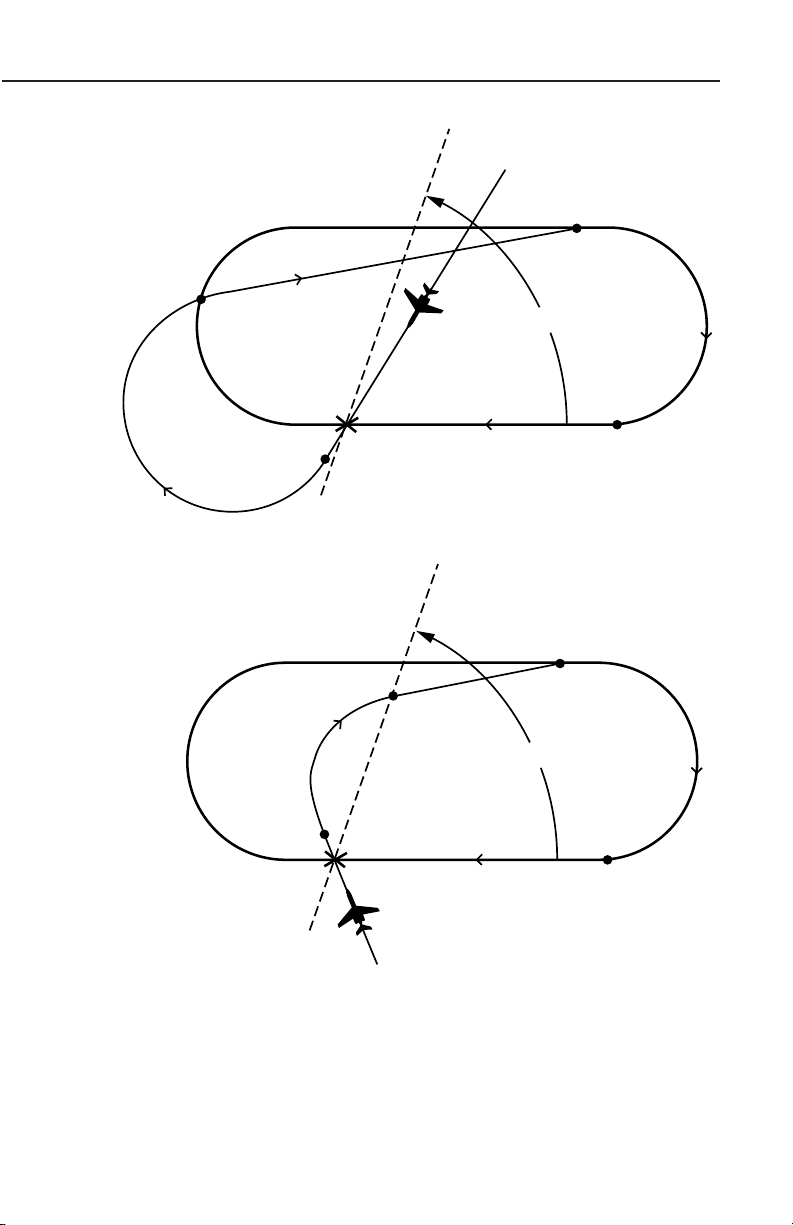
Page Display Definitions
70°
Outbound
End Turn
Point
Holding Course
Entry Course
70°
Outbound
End Turn
Point
Holding Course
Entry Course
Rev. 0
Direct Entry Pattern
Figure 2-70
GNS-XL Flight Management System
2-59
Page 91

Page Display Definitions
70°
Turn Anticipation
Holding Course
Leg Length
30° From Holding Course
Direct to
Holding Fix
Entry Course
70°
Holding Course
30° From Holding Course
Leg Length
Entry Course
2-60
Teardrop Entry Pattern
Figure 2-71
GNS-XL Flight Management System
Rev. 0
Page 92

Page Display Definitions
Go Direct to
Holding Fix
Leg Length
Holding Course
Entry Course
110°
Note Path of 1st
lap of holding
pattern after
entry procedure
Holding Course
Entry Course
110°
Out Bound End Turn Point
Rev. 0
Parallel Entry Pattern
Figure 2-72
GNS-XL Flight Management System
2-61
Page 93

Page Display Definitions
AT DILLY
HOLDING
INBOUND CRS T305
MAX HOLDING TAS 261
TURN DIR RIGHT
LEG TIME 1.5
LEG DIS (5.8)
EXIT MODE MANUAL
CANCEL?
HOLDING PATTERN 1/1
<
<
<
<
• HOLDING: indicates the system has entered the Holding Pattern.
(Figure 2-73)
• EXIT HOLD: indicates the system will exit the holding pattern the
next time over the holding fix.
INBOUND CRS (course):
The inbound holding course
in whole degrees. This field
can be True or Magnetic
according to the display
mode selected by the
TRUE/MAG switch input. A
T appears if in the True
mode (Figure 2-73). The T
field will be blank if the system is Magnetic mode.
MAX HOLDING TAS:
This field is computed based on configuration module max holding
indicated airspeed and worst case winds. It represents the maximum
true airspeed in the holding pattern that will assure that the aircraft
remains in protected airspace. (Figure 2-73)
Figure 2-73
TURN DIR (direction):
RIGHT indicates the standard default holding pattern turn direction.
The non-standard LEFT turn can be accessed using the BACK Key
when the cursor is over this field. (Figure 2-73)
LEG TIME:
Holding Pattern inbound leg time in minutes and tenths (1.0 to 9.9).
(Figure 2-73)
NOTE: The LEG TIME may be in parentheses indicating that the
time has been calculated using LEG DIS.
LEG DIST (distance):
Holding Pattern inbound leg distance in nautical miles (1.0 nm to
50.0 nm). (Figure 2-73)
NOTE: The LEG DIS may be in parentheses indicating that the dis-
tance has been calculated using LEG TIME.
2-62
GNS-XL Flight Management System
Rev. 0
Oct/96
Page 94

Page Display Definitions
POS N 33 37.50
W116 09.50
IDENT -----
FIX ----------
----------
DIF ----------
----------
POSITION FIX
<
<
<
EXIT MODE:
The MANUAL default indicates the system will stay in the holding
pattern indefinitely. Using the BACK Key with the cursor over this
field AUTO can be selected if the ENT key is pressed. The system
will then execute a holding pattern entry and exit the next time crossing the fix waypoint. (Figure 2-73)
NOTE: If a holding pattern is selected an HP is annunciated next to
the waypoint on Flight Plan, Navigation and Direct To Pages.
OK? ENT:
Depressing ENT Key when this prompt appears at the bottom of the
Holding Pattern Page programs a Holding Pattern for a particular
waypoint.
NOTE: The cursor will not appear in this field.
CANCEL:
Used to cancel a holding pattern. (Figure 2-73)
POSITION FIX PAGE
This page is accessed by depressing the HOLD Key anytime the cursor is not displayed over a waypoint.
POS:
The composite (system) position coordinates at the moment the
HOLD Key was depressed in degrees, minutes, and hundredths of
minutes. (Figure 2-74)
IDENT:
The alphanumeric designator
of the reference waypoint
used to check or update
position. (Figure 2-74)
FIX :
The actual coordinates of the
reference point in degrees,
minutes, and hundredths of
minutes. (Figure 2-74)
Rev. 0
Oct/96
GNS-XL Flight Management System
Figure 2-74
2-63
Page 95

Page Display Definitions
KDAL BOSEY
DFW BULEY
TO HART HNN
19DFW SUMET
HP ELD AIR
MEI CYN
DELBE BUONO
VUZ DPK
VZV GWENY
DIRECT 1/2
<
<
<
<
<
<
<
<
<
<
DIF:
The difference between the composite position and the FIX (or other
sensor) position in degrees, minutes and hundredths of minutes.
(Figure 2-74)
NOTE: Position coordinates of individual sensors and the difference
between those sensor positions and the composite (system) position
may be displayed by moving the cursor over the FIX field and
depressing the BACK Key. The composite position may be updated
to the most accurate sensor by pressing the BACK Key until the
desired sensor appears, then pressing the ENT Key twice.
DIRECT TO SECTION ( Æ KEY)
DIRECT TO PAGES
DIRECT 1/2 (Page 1 of 2)
This display is accessed through theÆÆkey and presents a listing of
all Active Flight Plan waypoints on as many pages as is appropriate
to display all of the waypoints. The cursor may be positioned over
any desired identifier (ahead of or behind the aircraft) to proceed
DIRECT (Figure 2-75). A new waypoint may be added to the flight
plan to proceed direct.
TO:
When this page is accessed,
the cursor is displayed over
the current TO waypoint.
(Figure 2-75)
The following may also be
displayed with a waypoint: HP
(Holding Pattern), PT
(Procedure Turn), MAP
(Missed Approach Point),
FAF (Final Approach Fix),
and IAF (Initial Approach Fix).
2-64
Figure 2-75
GNS-XL Flight Management System
Rev. 0
Page 96

DIR CLOSEST ARP 2/2 (Page 2 of 2)
TO 312 344/ 10
I18 045/ 14
I43 301/ 29
KUNI 344/ 29
KCRW 141/ 31
KHTS 230/ 34
I28 254/ 35
KPMH 281/ 39
KPKB 040/ 45
DIR CLOSET ARP 1/2
>
>
>
>
>
<
<
<
<
<
<
<
<
<
<
DIRECT TO CLOSEST AIRPORT: The Closest Airport
page is the last page in the
DIRECT TO section. Up to
nine airports are displayed,
in order of their proximity to
the aircraft, with the closest
airport listed first. (Figure 2-
76)
NOTE: Airports listed from
the database on this page
have runways 3000 ft long or
greater and are hard surfaced.
WAYPOINT SECTION
WAYPOINT PAGES
Waypoints fall into four categories:
• Database generated
Page Display Definitions
Figure 2-76
• Pilot entered (personalized/ offset)
• Special
• Obsolete
Waypoint Pages can be accessed from any FLIGHT PLAN, NAV,
, HOLD, INITIALIZATION, HEADING, or TRIP PLAN/FUEL PLAN
Pages.
DATABASE WPT 1/1 (Page 1 of 1) Database Generated
Waypoints
This page is accessed by typing in a waypoint identifier or by placing
the cursor over a waypoint identifier and pressing ENT.
Database Generated Waypoints are automatically updated when
accessed and cannot be modified by the operator. The four basic
types of waypoints residing in the data base are navaids, airports,
intersections and special waypoints.
Rev. 0
Oct/96
GNS-XL Flight Management System
ÆÆ
2-65
Page 97

Page Display Definitions
WAYPOINT TRM
PORTU
POS N 3845.60
W02705.60
FREQ 116.20
VAR W 14
ELEV 172
NDB-ENTER
DATABASE WPT 2/4
WAYPOINT TRM
USA
POS N 3337.70
W11609.60
FREQ 116.20
VAR E 13
ELEV -110
NDB-ENTER
DATABASE WPT 1/4
VHF Navaids
WAYPOINT:
Alphanumeric designator for
the Navaid. (Figure 2-77)
NOTE: If the waypoint has a
duplicate identifier in the
database, for another location, the closest waypoint to
the aircraft position will be
shown and the country code
will be displayed beneath the
waypoint identifier. (Figure
2-78)
Press the NXT Key to
sequence to the next waypoint page with a different
country code. The PRV Key
can be used to sequence
backward through the waypoint pages. Additional
country codes and corresponding POS coordinates
will be sequentially displayed.
Figure 2-77
Figure 2-78
POS:
The coordinates of the waypoint as stored in the database memory.
(Figure 2-77)
FREQ:
The VHF frequency for the station. (Figure 2-77)
VAR:
The magnetic variation of the station. (Figure 2-77)
ELEV:
The elevation in feet of the station (DME equipped VHF Navaids
only). A (-) indicates elevation is below sea level. (Figure 2-77)
NDB -ENT:
The procedure for accepting the waypoint from the Navigation Data
Base is to depress the ENT Key. (Figure 2-78)
2-66
GNS-XL Flight Management System
Rev. 0
Oct/96
Page 98

Page Display Definitions
WAYPOINT PRND
CAN
POS N 54 15.80
W130 25.40
NDB-ENTER
DATABASE WPT 1/14
WAYPOINT KSNA
ARP
POS N 33 40.50
W117 52.10
OM19R RW19R
RW01L
RW01R
RW19L
DATABASE WPT 1/1
<
<
<
Non-Directional Beacons (NDBs)
NDBs stored in the internal
database are listed in
Jeppesen publications with a
2 or 3 letter identifier. To distinguish these NDBs from
VHF NAVAIDS, you must
add an "NB" suffix to the
database identifier. Example:
To access the Prince Rupert
(PR) NDB, you must enter
PRNB. (Figure 2-79)
Airports
International Civil Aviation Organization (ICAO) identifiers are used to
access data in the database.
ICAO identifiers differ in some cases from those familiar to many
pilots.
The following are guidelines to access information from the database:
Except for a few hundred 3 or 4 letter/number airport identifiers in
Alaska, Canada and the Continental USA, all airport identifiers stored
in the database have 4 letters.
Figure 2-79
In most cases, these identifiers begin with a letter that
corresponds to the geographic area in which the airport is located. The ICAO
code letter prefix for
Continental USA airports is
"K". Hawaii and Alaska
identifiers begin with "P".
To access a 4 character
identifier, use the IDENTIFIER found in the Jeppesen
charts. For example, enter
KSNA for Santa Ana. (Figure 2-80)
Rev. 0
Oct/96
Figure 2-80
GNS-XL Flight Management System
2-67
Page 99

Page Display Definitions
WAYPOINT KNEW
ARP
POS N 30 02.60
W090 01.70
RW09 RW36L
RW18L RW36R
RW18R
RW27
DATABASE WPT 5/8
<
<
<
WAYPOINT 31J
ARP
POS N 30 10.90
W082 34.60
RW10
RW26
DATABASE WPT 6/8
<
WAYPOINT OM19R
KSNA
POS N 33 46.70
W117 48.30
OM19R RW19R
RW01L
RW01R
RW19L
DATABASE WPT 7/8
<
<
<
• If the airport shows a 3 letter IDENTIFIER, add the correct ICAO prefix letter.
Example: NEW (New
Orleans Lake Front) add a
"K" prefix and enter KNEW
(Figure 2-81).
• If the airport shows a 3
character (letters and numbers) IDENTIFIER, enter the
identifier as printed.
Example: 31J (Lake City,
Florida) enter 31J. (Figure 2-
82)
Airport Reference Points,
Outer Markers, Runway
Thresholds
Airport Reference Point
(ARP) coordinates are
always displayed in
response to the airport identifier.
Figure 2-81
Figure 2-82
Outer markers and runway
thresholds for which data is
stored in the database are
also displayed on the airport
waypoint page (also known
as airport continuation
records page) and can be
accessed by pressing the
PRV or NXT Key or Line
Select Keys. (Figure 2-83)
The selected outer marker or
runway threshold will then be
Figure 2-83
displayed in place of the airport identifier in the waypoint field. The airport identifier Shifts to and
replaces the ARP field below. (Figure 2-83)
2-68
GNS-XL Flight Management System
Rev. 0
Oct/96
Page 100

Page Display Definitions
WAYPOINT WHALE
USA
POS N 42 11.87
W066 59.96
NDB-ENTER
DATABASE WPT 1/2
WAYPOINT GLOBAL
USA
POS ---------
---------
944 WPTS AVAIL
PILOT ENTERED WPT
Intersections/Enroute
Waypoints
Most intersection waypoint
identifiers consist of 5 letters.
However, 3, 4, and 5 letter
and number combinations
exist. To access these waypoints, simply enter the identifier from the Jeppesen
chart. Example: WHALE
intersection. (Figure 2-84)
SPECIAL DATABASE WAYPOINTS
PILOT ENTERED WPT (Personalized) Waypoint
The operator is responsible for generating the waypoint data and
maintaining its accuracy.
WAYPOINT:
The alphanumeric designator selected by the pilot. Identifiers can
consist of up to six characters, and can be composed of any of the
characters on the keyboard. (Figure 2-85) However, the asterisk (*)
and pound sign (#) have special functions.
Figure 2-84
POS:
Blank fields for entering the
latitude and longitude of the
waypoint. When initially
accessed (waypoint not yet
in memory) the coordinate
fields are both dashed and
covered by a double cursor.
(Figure 2-85)
WPTS AVAILABLE:
The number of waypoints available in memory after this waypoint is
defined. Maximum waypoint storage in non-volatile memory is 999.
(Figure 2-85)
Rev. 0
Oct/96
Figure 2-85
GNS-XL Flight Management System
2-69
 Loading...