

Page 1
FFT
The FFT Fire Fighter T elephone Module provides supervision,
annunciation and control for local and remote telephone handsets as
well as an optional remote microphone.
CAUTION! Make sure to observe all of the following precautions:
• Remove all power (AC and DC) before installing or removing any modules since damage to components
may occur if power remains applied.
• Circuit boards contain static-sensitive components. Always ground yourself with a proper wrist strap
before handling any boards so that static charges are removed from the body. Use static suppressive
packaging to protect electronic assemblies.
FFT Replacement
1. Make certain that AC and DC power have been removed from the panel.
2. Unplug the terminal block connectors from TB1, TB2 and TB3 located on the top edge of the defective FFT board
(label to ensure reinstallation in correct positions).
3. Unplug the panel telephone handset from Phone Jack J1 located on bottom center of the defective FFT board.
4. Remove two mounting screws which hold the defective FFT board to the mounting bracket standoffs and set aside.
5. Carefully lift the defective FFT board from the slot in the bottom of the mounting bracket.
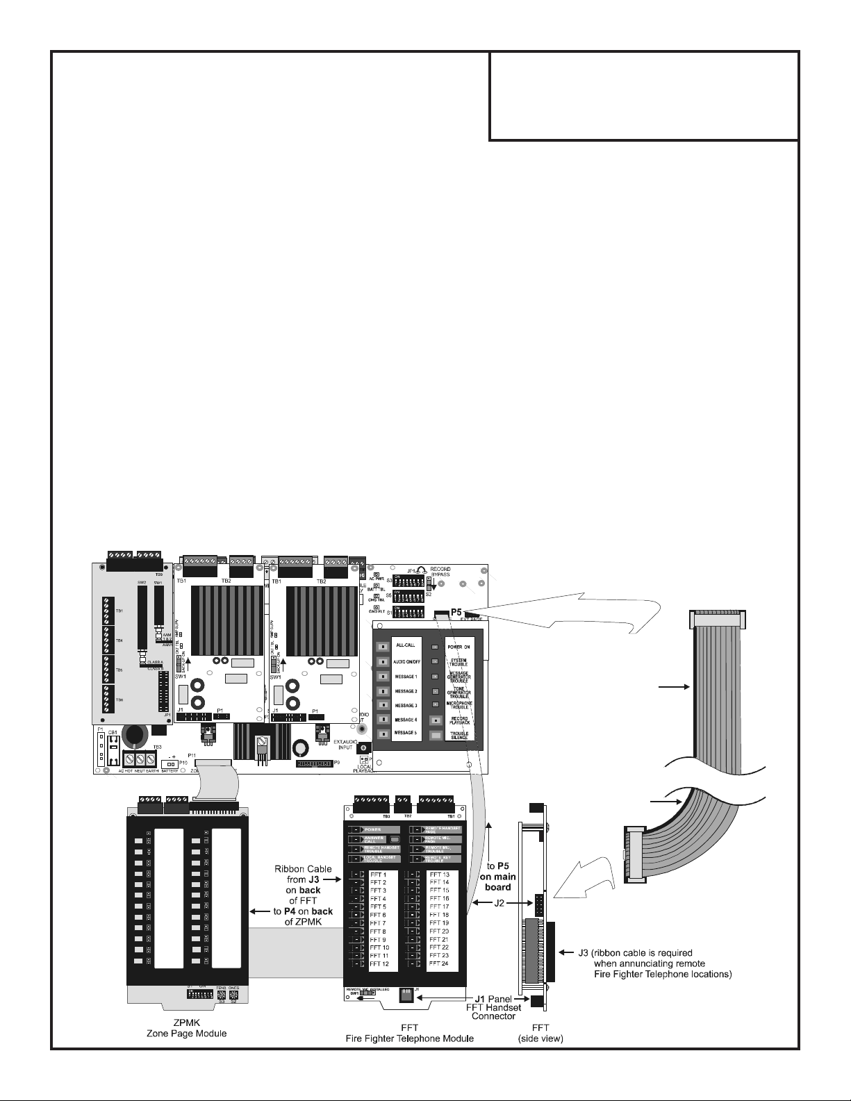
6. Remove the ribbon cable connectors from J2 on the right side of the board and J3 on the back of the defective FFT
board.
7. Connect cable between J2 on the new FFT board and P5 on Zone Split Audio Panel main circuit board as illustrated
below.
8. If telephone call-ins are to be annunciated on the ZPM, connect cable between J3 on the FFT and P4 on the back
of the ZPM(K) module. Note that the J3 and P4 ribbon cable connectors are keyed to prevent incorrect
installation. Refer to following illustration for connector locations.
Fire Fighter Telephone Module
Product Installation Drawing
Document 52246 Rev A 1/16/08 ECN 07-873
Make certain that the ribbon cable is
installed with the red stripe oriented
as illustrated below.
Audio Panel with Zone Split
P5
red stripe
red stripe
J2
Page 2

9. Insert the bottom of the new FFT board in the slot located in the bottom right of the mounting bracket as indicated in illustration below .
10. Secure the module to the mounting bracket standoffs with the two mounting screws.
11. Wire the terminal blocks TB1, TB2 and TB3 as described in the illustration below . Plug the terminal block
connectors which were disconnected in step 2 into TB1, TB2 and TB3 located on the top edge of the FFT.
12. Plug the panel telephone handset into Phone Jack J1 on bottom center of FFT.
13. Set switch SW1 to correct position. SW1 positioned to the left (as illustrated below) indicates that the remote
microphone is installed. SW1 positioned to the right indicates that a remote microphone is not installed.
14. Set switch SW2 to correct position. SW2 positioned up (as illustrated below) indicates that the audio wiring to
the Remote Page Jack is configured for 2-wire Class B.
15. Reapply AC and DC power
16. Program the host F ACP for proper operation with the Audio Panel
17. Test the panel for proper operation.
T erminal Block Connectors
TB1TB2TB3
SW1
FFT
J1
SW2
Ribbon Cable
Connectors
J2 (on side)
J3 (on back)
Standoff
Slot
Standoff
Mounting Bracket
Document 52246 Rev A ECN 07-873 1/16/08
 Loading...