

Page 1

ETDOC-X615–R120.1 ENTIS R120.1 User’s Manual i
User’s Manual
ENTIS R120.1
Page 2
ii ENTIS R120.1 User’s Manual ETDOC-X615–R120.1
PREFACE
About this Guide
This manual describes how to operate the ENTIS system. It has been written for
operators, as well as system supervisors, to provide them with all the information
required to operate the system.
For installation details refer also to the ENTIS Installation Guide.
Safety and prevention of damage
‘Cautions’, and ‘Notes’ have been used throughout this manual to bring special
matters to the immediate attention of the reader.
A Caution draws attention to an action which may damage the
equipment.
A Note points out a statement deserving more emphasis than the
general text, but does not deserve a “Warning” or a “Caution”.
Additional information
Contact Honeywell, or its representative, if you require additional information.
Also, refer to the list of related documents in Appendix for more information.
Legal aspects
The information in this manual is copyright property of Honeywell, Netherlands.
Honeywell disclaims any responsibility for personal injury or damage to
equipment caused by:
Deviation from any of the prescribed procedures
Execution of activities that are not clearly documented
Copyright 2020 Honeywell. All rights reserved.
Reproduction in any form without the prior consent of Honeywell is not allowed.
This manual is for information only. The contents, descriptions and specifications
are subject to change without notice. Honeywell accepts no responsibility for any
errors that may appear in this manual.
The warranty terms and conditions applicable in the country of purchase in
respect to Honeywell products are available from your supplier. Please retain
them with your proof of purchase.
Page 3
ETDOC-X615–R120.1 ENTIS R120.1 User’s Manual iii
Support
For support, contact your local Honeywell Process Solutions Customer Contact Centre (CCC). To
find your local CCC visit the website,
https://www.honeywellprocess.com/en-
US/contactus/pages/default.aspx
Revision History
ENTIS Installation and Configuration Guide (This document)
ETDOC-X615-en-101A
September 2019 (1st Release)
ETDOC-X615-en-110.1
December 2019 (R110.1)
ETDOC-X615-en-120.1
June 2020 (R120.1)
Documentation References
The following list identifies publications that may contain information relevant to
the information in this document.
ETDOC-X612-en-R120.1
ENTIS Quick Start Guide
ETDOC-X613-en-R120.1
ENTIS Installation and Configuration Guide
EHDOC-X136-en-510A
Experion HS Software Installation Users Guide
EHDOC-XX75-en-510A
Network and Security Guide
ENTIS Hub page for documentation and videos: https://www.honeywellprocess.com/en-
US/online_campaigns/terminals/Pages/Terminals-HUB.aspx.
ENTIS documentation on HPS web: https://www.honeywellprocess.com/en-
US/explore/products/terminal-operations/tank-storage/Pages/tank-inventorysystems.aspx.
Contacts
See back page for details
Page 4

iv ENTIS R120.1 User’s Manual ETDOC-X615–R120.1
Contents
PREFACE ........................................................................................................................................... ii
INTRODUCTION ................................................................................................................................ 1
Real Time Inventory ................................................................................................................. 1
Numerical & Graphical Display ................................................................................................. 1
Networking ............................................................................................................................... 1
Alarm System ........................................................................................................................... 1
Hot Standby & CIU Redundancy Support ................................................................................ 1
ENTIS Redundancy Support .................................................................................................... 2
Dual Gauges Support ............................................................................................................... 2
954 Servo Test Alarm Support ................................................................................................. 2
50 Point Density Profile Support .............................................................................................. 2
Reporting Enhancements ......................................................................................................... 2
400 Tanks Support ................................................................................................................... 2
ENTIS Language Support ........................................................................................................ 2
Experion Alarms & Events Screen Language Support ............................................................. 2
INTERFACE GUIDELINES ................................................................................................................ 3
Help .......................................................................................................................................... 3
Data Status ............................................................................................................................... 3
SECURITY CONSIDERATIONS ........................................................................................................ 4
General Guidelines ................................................................................................................... 4
Signed Assemblies ................................................................................................................... 4
Network Shares ........................................................................................................................ 5
Access Control List ................................................................................................................... 5
Backup & Restore .................................................................................................................... 5
User Accounts and Roles ......................................................................................................... 6
Physical and Environmental Considerations ............................................................................ 6
System Monitoring .................................................................................................................... 6
Vulnerability Reporting ............................................................................................................. 6
TOOLBAR .......................................................................................................................................... 7
Toolbar ..................................................................................................................................... 7
Status bar ................................................................................................................................. 7
MANAGE DISPLAYS ......................................................................................................................... 9
Manage Group ......................................................................................................................... 9
Manage Views ........................................................................................................................ 11
Manage Filters ........................................................................................................................ 14
GROUP VIEW ................................................................................................................................. 16
GROUP DETAIL ............................................................................................................................... 17
Delta column .......................................................................................................................... 19
Critical / Operation PAL Column ............................................................................................ 22
Remark Column ..................................................................................................................... 27
TANK DETAIL .................................................................................................................................. 30
GAUGE COMMANDS ...................................................................................................................... 35
Running Dipping Commands ................................................................................................. 39
Running Displacer Commands ............................................................................................... 40
Scheduling Gauge Command ................................................................................................ 41
Page 5

ETDOC-X615–R120.1 ENTIS R120.1 User’s Manual v
MANUAL OVERWRITE ................................................................................................................... 43
Performing a Manual Overwrite .............................................................................................. 44
PROFILES ....................................................................................................................................... 47
Profile screen examples .......................................................................................................... 50
TOTALIZER ..................................................................................................................................... 53
WHAT IF .......................................................................................................................................... 55
REPORTS ........................................................................................................................................ 59
Report Printing ........................................................................................................................ 59
Report Scheduling .................................................................................................................. 63
Templates ............................................................................................................................... 64
MANAGE TASKS ............................................................................................................................. 70
HELP ................................................................................................................................................ 72
SETTINGS ....................................................................................................................................... 73
ALARMS ................................................................................................................................. 73
Product Color Code ................................................................................................................ 75
Clock Sync .............................................................................................................................. 76
Manage Files .......................................................................................................................... 76
Reporting ................................................................................................................................ 77
HOT STANDBY & REDUNDANCY SUPPORT ENTIS .................................................................... 78
Hot Standby & Redundancy Support (CIU 888) ..................................................................... 80
How to Perform Manual Switch Over ...................................................................................... 81
ALARMS .......................................................................................................................................... 82
CONFIGURE ALARMS ........................................................................................................... 82
VIEW ALARMS ....................................................................................................................... 85
EVENTS ........................................................................................................................................... 89
Viewing Events ....................................................................................................................... 89
HISTORICAL AND REALTIME TRENDING .................................................................................... 93
INDEX ............................................................................................................................................ 103
Table of Tables
Table 1: Data Status .......................................................................................................................... 3
Table 2: Displacer Commands ......................................................................................................... 37
Table 3: Entity Fields ........................................................................................................................ 44
Table 4: Configuration Alarms .......................................................................................................... 82
Page 6

vi ENTIS R120.1 User’s Manual ETDOC-X615–R120.1
Table of Figures
Figure 1: Tool bar .............................................................................................................................. 7
Figure 2: Status bar ........................................................................................................................... 7
Figure 3: Manage Groups .................................................................................................................. 9
Figure 4: Reset Views ..................................................................................................................... 11
Figure 5: Manage Views .................................................................................................................. 12
Figure 6: Manage Filters .................................................................................................................. 14
Figure 7: Group View ....................................................................................................................... 16
Figure 8: Group Detail ..................................................................................................................... 18
Figure 9: Delta Column .................................................................................................................... 19
Figure 10: Delta Column Group ....................................................................................................... 20
Figure 11: Delta Column Report ...................................................................................................... 21
Figure 12: Alarm Column ................................................................................................................. 22
Figure 13: Alarm Column Views ...................................................................................................... 23
Figure 14: Group Detail Alarm Column ........................................................................................... 24
Figure 15: Alarm Column HA ........................................................................................................... 25
Figure 16: Alarm Column HA Ack .................................................................................................... 25
Figure 17: Alarm Column LA ........................................................................................................... 26
Figure 18: Remarks Column ............................................................................................................ 27
Figure 19: Remarks Views .............................................................................................................. 28
Figure 20: Remarks Views edit ........................................................................................................ 29
Figure 21: Remarks Views with history ........................................................................................... 29
Figure 22: Tank Detail ..................................................................................................................... 31
Figure 23: Tank Detail Floating ....................................................................................................... 32
Figure 24: Tank Detail Sphere ......................................................................................................... 33
Figure 25: Tank Detail Icon ............................................................................................................. 34
Figure 26: Gauge Commands ......................................................................................................... 35
Figure 27: Dipping Command .......................................................................................................... 36
Figure 28: Displacer command ........................................................................................................ 37
Figure 29: Tank Gauge Alarm ......................................................................................................... 38
Figure 30: Displacer ........................................................................................................................ 39
Figure 31: Displacer ........................................................................................................................ 40
Figure 32: Schedule Command Screen .......................................................................................... 41
Figure 33: Scheduling screens ........................................................................................................ 42
Figure 34: Manual Overwrite ........................................................................................................... 43
Figure 35: Manual Overwrite Parameter ......................................................................................... 45
Figure 36: Create Profile ................................................................................................................. 48
Figure 37: Profile ready ................................................................................................................... 49
Figure 38: Temperature profile ........................................................................................................ 50
Figure 39: Density Profile ................................................................................................................ 51
Figure 40: Interface Profile .............................................................................................................. 51
Figure 41: Density and Temperature profile .................................................................................... 52
Figure 42: Density profile ................................................................................................................. 52
Figure 43: Totalizer .......................................................................................................................... 53
Figure 44:Totalizer_All ..................................................................................................................... 53
Figure 45: Totalizer Icon .................................................................................................................. 54
Figure 46: What If ............................................................................................................................ 55
Figure 47: What – If layout .............................................................................................................. 56
Page 7

ETDOC-X615–R120.1 ENTIS R120.1 User’s Manual vii
Figure 48: What – If Start ................................................................................................................. 57
Figure 49: What – If Reload ............................................................................................................. 58
Figure 50: Reports ........................................................................................................................... 59
Figure 51: Reporting icon ................................................................................................................. 60
Figure 52: Tank detail report ............................................................................................................ 60
Figure 53: Browse Reports .............................................................................................................. 62
Figure 54: Schedule report ............................................................................................................... 63
Figure 55: Schedule report screens ................................................................................................. 64
Figure 56: Group detail report .......................................................................................................... 65
Figure 57: Tank detail ...................................................................................................................... 66
Figure 58: Delta column report ......................................................................................................... 67
Figure 59 - What if .. report .............................................................................................................. 68
Figure 60: Manage Tasks ................................................................................................................ 70
Figure 61: Scheduling screen .......................................................................................................... 71
Figure 62: Confirmation Dialog ........................................................................................................ 71
Figure 63: Help ................................................................................................................................. 72
Figure 64: Help icon ......................................................................................................................... 72
Figure 65: Alarm Settings ................................................................................................................. 74
Figure 66: Product Color Code ........................................................................................................ 75
Figure 67: Clock Sync ...................................................................................................................... 76
Figure 68: File Cleanup .................................................................................................................... 76
Figure 69: Reporting Settings .......................................................................................................... 77
Figure 70: Configuration screen ....................................................................................................... 83
Figure 71: Alarm Configuration screen ............................................................................................ 84
Figure 72: View Alarms .................................................................................................................... 85
Figure 73: View Events .................................................................................................................... 90
Figure 74: Trends ............................................................................................................................. 99
Figure 75: Configure Trends .......................................................................................................... 100
Figure 76: Select the point ............................................................................................................. 100
Figure 77: Select the parameter ..................................................................................................... 101
Figure 78: View Trend .................................................................................................................... 101
Figure 79: Historical Trend ............................................................................................................. 102
Page 8

Page 9

ETDOC-X615–R120.1 ENTIS R120.1 User’s Manual 1
INTRODUCTION
ENTIS is a unique Tank Inventory Management System developed for Windows
10 Enterprise, and powered by the Experion platform, to display Tank inventory
data.
Real Time Inventory
ENTIS is a Windows 10 Enterprise application. Data is retrieved via dedicated
Communication Interface Units (CIU’s) and processed through to the open ENTIS
database. Various displays are available for inventory management. These
displays include bar graphs, tabular data, iconized tanks, and a whole range of
modules such as trending, report printing, and a “what if” tank calculator.
Numerical & Graphical Display
The graphical displays provide a quick overview of tank data. The numerical
displays can be customized to suit your own particular needs. These displays can
be either tank or group related. Several graphical displays are also available, and
tank images can be customized per tank if required.
Networking
The network facilities of the Experion system allow you to integrate ENTIS into
your plant’s networks.
Alarm System
ENTIS provides you with an array of programmable alarm set points. Privileged
users can create their own alarms for all measured and calculated data. During
inactive periods, tanks can be put into a leak detection mode. Alarms and
acknowledgements, together with all tank information, are stored and recorded for
future review and traceability.
Hot Standby & CIU Redundancy Support
The ENTIS system can be enhanced for use in critical applications with hot
standby and CIU redundancy support. CIU redundancy support can cover the
unlikely event of a network failure, providing sustained and reliable data to your
management system. After the occurrence of an error, the second CIU will
automatically start and take over the lost functionality. Following the switch over,
all gauge data will be rescanned and recalculated to ensure data reliability.
Page 10

2 ENTIS R120.1 User’s Manual ETDOC-X615–R120.1
ENTIS Redundancy Support
The ENTIS system can now be used in a redundant server mode, with automatic
failover capabilities.
Dual Gauges Support
ENTIS can now work with the CIU to support dual gauge systems, allowing for
two product levels to be used to generate a difference alarm.
954 Servo Test Alarm Support
ENTIS can be used to generate test alarms for the 954 servo.
50 Point Density Profile Support
ENTIS can now work with the 954 servo to support 50 point density profiles.
Reporting Enhancements
ENTIS reporitng now allows for the use of customized customer name, sites and
logos, on the standard and Legal Metrology-approved report set.
400 Tanks Support
ENTIS license now gives you the option to start with 5, 10, 15, 20, …310, 315,
320...400 tanks.
ENTIS Language Support
ENTIS now supports either of English, French, Italian or Dutch language. ENTIS
will appear in the language as being set at commissioning. User with Admin rights
can change the language of ENTIS when required.
Experion Alarms & Events Screen Language Support
ENTIS now allows user to view the alarm and event description in either of
English, French, Italian or Dutch language.
Page 11

ETDOC-X615–R120.1 ENTIS R120.1 User’s Manual 3
INTERFACE GUIDELINES
The ENTIS user interface consists of a set of inter-related graphical objects
together with a set of rules governing their deployment, such as windows, dialog
boxes, task icons, colours and others.
Although ENTIS is a Windows application, there are certain additional
conventions used in ENTIS that will be described in this chapter. This chapter
also describes a basic set of rules to help the user learn how to use ENTIS
Help
ENTIS supports the displaying of the PDF of the User’s Manual. Navigating to the
Help menu item will open the pdf version of the ENTIS User’s Manual.
Data Status
Measured and calculated data is indicated by a status sign.
The statuses are shown in the following table:
Table 1: Data Status
Sign
Description
Data is actual and approved
&
Data is manually overwritten
S
Data is stored and not approved
#
Data is not approved for Legal Metrology use
?
Data has reduced accuracy and is not approved
F
Data is in fail
K
Data is not being scanned (formerly called ‘killed’)
˄
Data is over range
˅
Data is under range
U
Data is uninitialized
S&W, Liq/Vol Ratio and Molar Weight are always manually entered
Page 12

4 ENTIS R120.1 User’s Manual ETDOC-X615–R120.1
SECURITY CONSIDERATIONS
General Guidelines
ENTIS runs on the Experion HS platform; therefore, Experion’s
security guidelines / recommendations should be followed in any
ENTIS deployment.
Experion HS provides a comprehensive Network and Security Guide
(ID: EHDOC-XX75-en-510A) that should be reviewed prior to an
ENTIS deployment. It contains numerous guidelines to help ensure a
secure deployment.
In addition to the information provided in that manual, this section
provides some additional security-related details.
This information is ENTIS-specific and is meant only to augment the
Experion documentation.
Signed Assemblies
Digitally signing files allows users to confirm that those files were
provided by Honeywell.
Honeywell has digitally signed the assemblies that it provides with
ENTIS. Note that this does not include third-party assemblies that are
not maintained as a part of the ENTIS product line.
Users can confirm that their ENTIS assemblies are signed by bringing
up the assembly properties via Windows Explorer.
Users can check for signing by right-clicking on the dll/exe, and
selecting Properties from the context menu.
If the ensuing dialog has a Digital Signatures tab, and there is a
“Honeywell Limited” signer listed, then your assembly has been
properly signed by Honeywell.
Page 13
SECURITY CONSIDERATIONS
ETDOC-X615–R120.1 ENTIS R120.1 User’s Manual 5
Network Shares
ENTIS creates the following network shares beyond what Experion configures,
and documents, in their Network and Security Guide.
Shares created by Server-Client install are as follows:
Name
Location
Nodes
Usage
ENTISRepository
C:\ProgramData\Ho
neywell\ENTIS
Server
Used by File Replication
to replicate contents to a
redundant server
Broker
C:\Program Files
(x86)\Mosquitto
Server
Used to exchange the
certificate and
configuration file with a
redundant server.
Access to the shares is limited to users of the groups Administrators, Product
Administrators and Local servers.
Access Control List
ENTIS will set up the appropriate access controls on its files for the application to
run securely.
This ACL configuration step is run automatically as a part of the installation
process.
In addition to the ENTIS-specific ACL settings, ENTIS also relies on the standard
Experion ACL implementation, as is described in the Experion Network and
Security Guide.
Backup & Restore
For the backup and restoration process for the node, please refer to the following
sections of the Experion PKS Backup and Restore User's Guide, EPDOC-X111-
en-431K on Honeywellprocess.com. Backups on a physical node.
1. Backups on a virtual node.
2. Restoring Physical Nodes.
3. Restoring Virtual Nodes.
Page 14

Security Considerations
6 ENTIS R120.1 User’s Manual ETDOC-X615–R120.1
User Accounts and Roles
User roles define the set of operations that a user is allowed to
perform. ENTIS leverages the Experion platform and its user roles.
For information on the roles, please refer to the “User accounts and
Experion user roles” section in the Network and Security Guide (ID:
EHDOC-XX75-en-510A). Note that the Legal Metrology user roles are
ENTIS specific and explained in more detail in the ENTIS Sealing
guide.
Physical and Environmental Considerations
While the security issues for ENTIS on Experion are largely the same
as for any IT server, the physical access of a tank information system
can be particularly important. For physical and environmental
considerations, please see the Physical and Environmental
Considerations section in the Network and Security Guide (ID:
EHDOC-XX75-en-510A).
System Monitoring
ENTIS and Experion provide a number of ways to detect potential
evidence of intrusion. The System Monitoring section of the Network
and Security Guide (ID: EHDOC-XX75-en-510A) provides details on
this subject. In addition to the information in that guide, it should be
added that ENTIS wll write events into the ENTIS event log, which is
available through the Windows event viewer.
Vulnerability Reporting
In the previously mentioned Network and Security Guide (ID:
EHDOC-XX75-en-510A), please refer to the section titled “How to
report a security vulnerability” for information pertaining to reporting
potential security vulnerabilities against Honeywell products.
Page 15
ETDOC-X615–R120.1 ENTIS R120.1 User’s manual 7
TOOLBAR
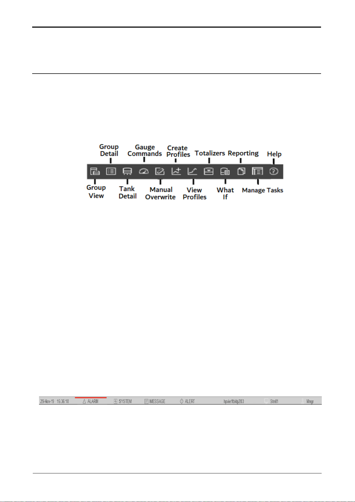
Toolbar
The toolbar is present in Experion Station. It offers a fast navigation tool for
ENTIS displays. Based on their access level, users can navigate to ENTIS
screens by clicking on the associated menu icons.
Figure 1: Tool bar
Status bar
The status bar includes the following display areas:
DateTime
Displays the current system date and time.
Alarms
Whenever an alarm is raised, the alarm icon will start blinking in red. Clicking on
the icon will open the Alarm display.
System
If it is blinking in blue, the system status is ok. If any system related issues come
up, it will start blinking in red. Click on it to open the system status view.
Message, Alert
Any message or alert logged by Experion will be available here.
Figure 2: Status bar
Page 16

Toolbar
8 ENTIS R120.1 User’s Manual ETDOC-X615–R120.1
Server Name
Server to which Experion Station is connected. Click on the icon to
view details.
Station Name
The connected Station name will be displayed here.
Role
Displays the logged-in user role. Click on it to enter the credentials
and change the role.
Page 17
ETDOC-X615–R120.1 ENTIS R120.1 User’s Manual 9
MANAGE DISPLAYS
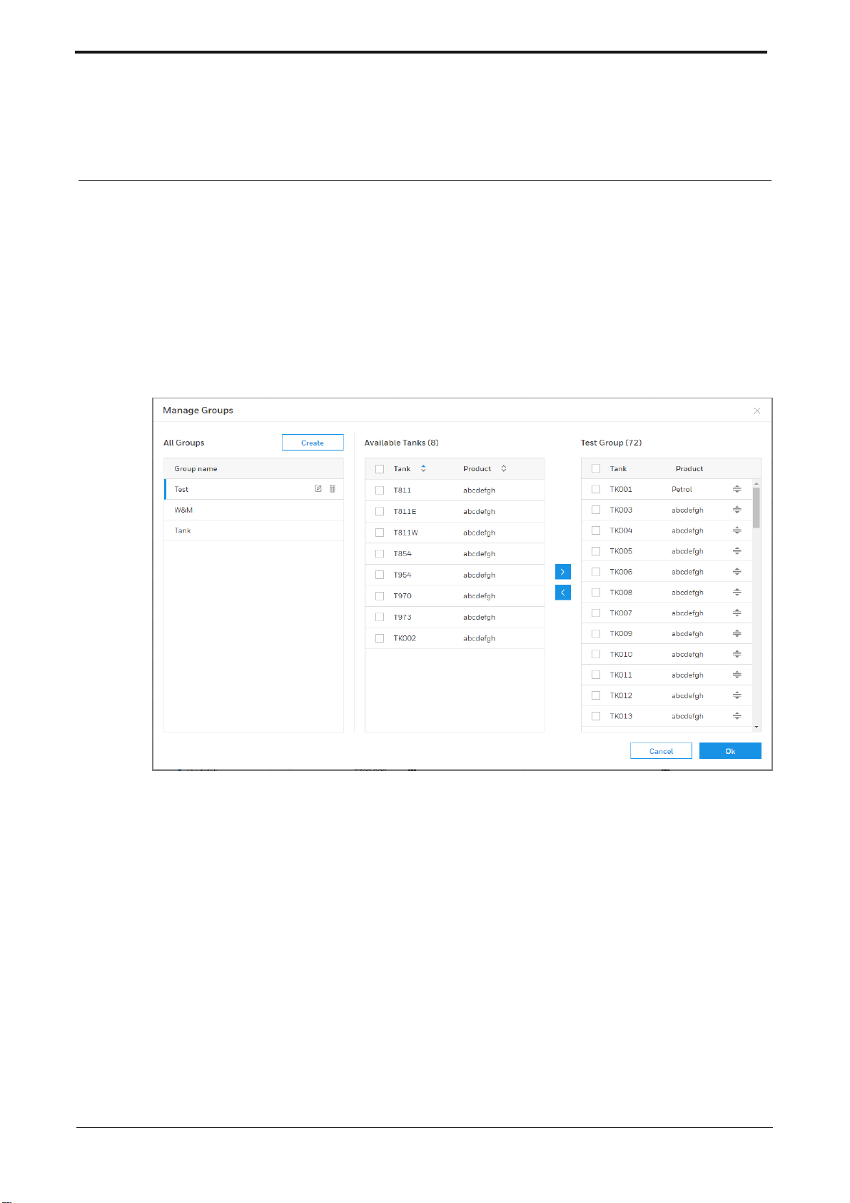
Manage Group
Tank groups can be defined to allow for easier navigation between subsets of
tanks.
The Manage Groups dialog can be opened from the Group View, Group Detail, or
Totalizers screen.
Figure 3: Manage Groups
This dialog displays the following main sections:
On the left side, all created tank groups are displayed.
In the middle part, the available tanks to be added to the tank group are
shown.
At the right side, the tanks which are a member of the selected tank group
are displayed.
Page 18
Manage Displays
10 ENTIS R120.1 User’s Manual ETDOC-X615–R120.1
Creating a Group
1. Log on as a user with SUPV permissions (or higher).
2. Click the Manage Groups icon from either the Group View or the Group
Detail display. The Manage Groups dialog opens.
3. Click on Create:
An edit field opens where you can enter the tank group name.
4. Enter the tank group name and click Create.
The tank group is added to the list of created Tank Groups.
5. In the middle part of the screen, select the tanks that you want to add to
the group.
6. Click on
The selected tanks are moved from the middle panel to the right part of the
dialog.
7. Click OK
The dialog closes.
The newly created group can be selected in the Group selector dropdown
box on the various UI screens.
8. Similarly, to remove tanks from a group, select the tanks in the right part of
the screen and click on
Note that the “All” group is available by default and cannot be removed or altered.
Page 19
Manage Displays
ETDOC-X615–R120.1 ENTIS R120.1 User’s Manual 11
Manage Views
The Group Detail task displays tank inventory data for multiple tanks in a tabular
format. Tanks are organized in rows, while the entities are displayed in columns.
This dialog enables the user to customize the view that defines the columns to be
displayed in Group Detail. The first column (Tank name) is fixed.
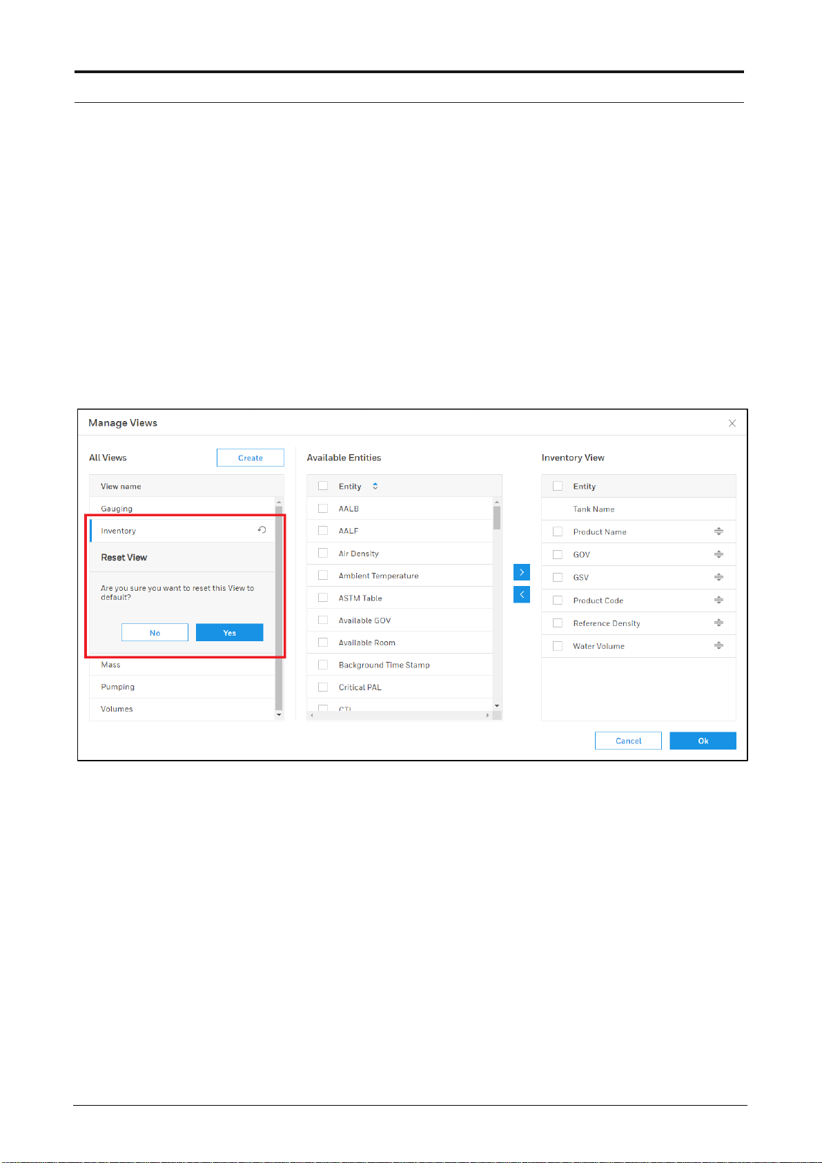
A number of predefined views are available; it is also possible to create new
views.
The predefined views can be altered, but not deleted. However, they can be reset
as shown below:
Figure 4: Reset Views
Newly created views can be altered and deleted.
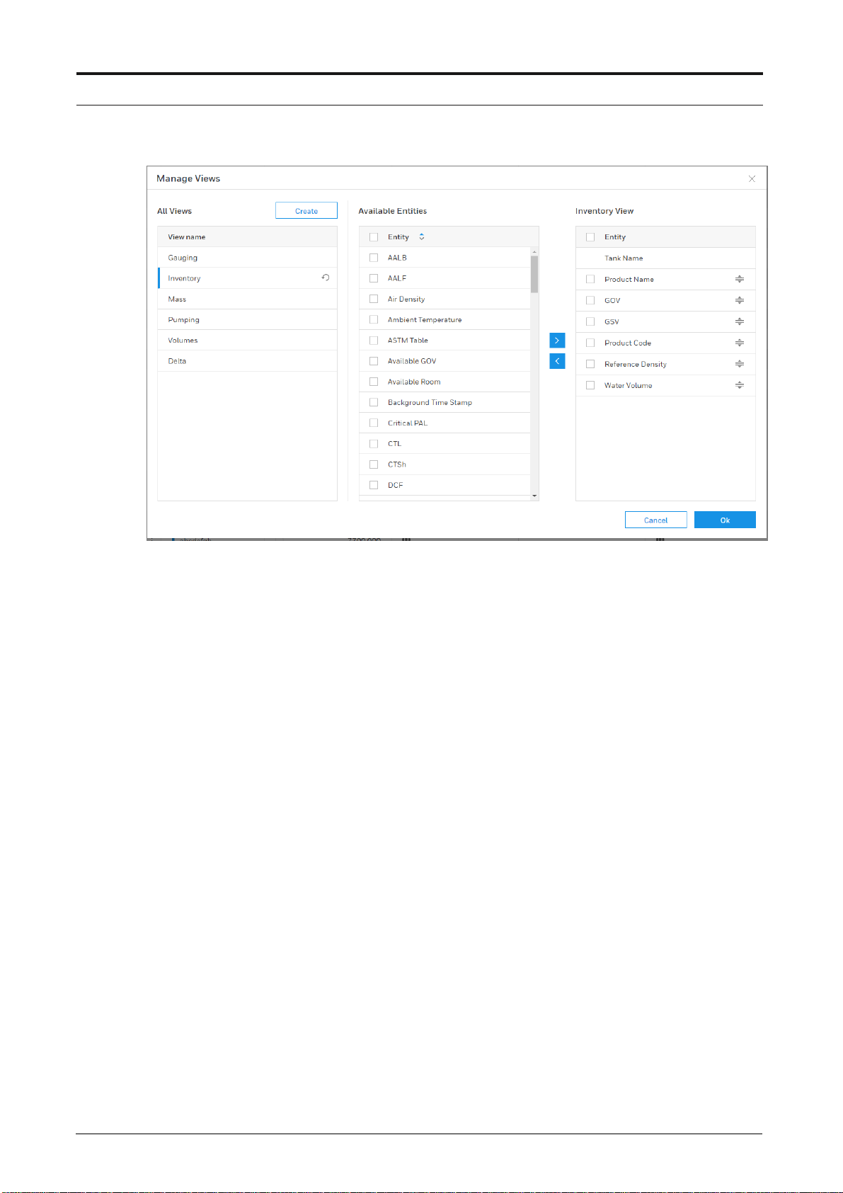
The Manage Views dialog can be launched from the Group Detail screen.
Page 20
Manage Displays
12 ENTIS R120.1 User’s Manual ETDOC-X615–R120.1
Figure 5: Manage Views
This dialog displays the following main sections:
At the left side, all available views are shown.
In the middle part, the available entities to be added to the view are
displayed.
At the right side, the entities which are available in the selected view are
shown.
Page 21

Manage Displays
ETDOC-X615–R120.1 ENTIS R120.1 User’s Manual 13
Creating a view
1. Log on as a user with SUPV level permissions (or higher).
2. Click the Manage Views icon from the Group Detail display.
The Manage Views dialog opens.
3. Click on Create
An edit field opens where you can enter the view name.
4. Enter the view name and click Create
The view is added to the list of available views.
5. In the middle pane of the dialog, select the entities that you want to add to
the view.
6. Click on >
The selected entities are moved from the middle pane to the right side of
the dialog.
7. Click OK
The window closes. The newly created view can be selected in the View
selector dropdown box on Group detail.
8. Similarly, to remove entities from a view, select the entities in the right part
of the screen and click on <
Note: the order of the entities can be changed by dragging and dropping them on
the right part of the Manage Views dialog.
Page 22
Manage Displays
14 ENTIS R120.1 User’s Manual ETDOC-X615–R120.1
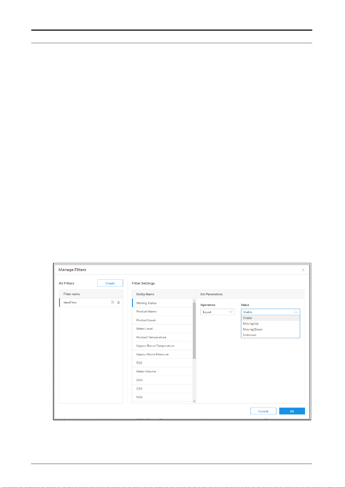
Manage Filters
This dialog offers the possibility to define filters on tanks to be displayed in a Tank
Group.
A few examples of filters:
Show tanks with a certain Product name.
Show tanks with a Product temperature above a certain value.
Show tanks with a Product level between 2 values.
The Manage Filter dialog can be launched from the Group Detail display.
Window layout
This window displays the following main sections:
At the left side, all created filters are shown.
In the middle part, the entities that can be used in a filter are displayed.
At the right side, the configured parameters (Operation, Value) for the
selected filter are shown.
Figure 6: Manage Filters
Page 23

Manage Displays
ETDOC-X615–R120.1 ENTIS R120.1 User’s Manual 15
Creating a filter:
1. Log on as a user with SUPV level permissions (or higher - see note below)
2. Click the Filter icon from the Group Detail display.
Then click Manage Filters.
3. Click on Create
An edit field opens where you can enter the filter name.
4. Enter the filter name and click Create
The filter is added to the list of created filters.
5. In the middle part of the dialog, select the entity that you want to be used
in the filter.
6. In the right part of the dialog, select the Operation and the Value.
7. Click OK
The window closes. The newly created filter can be selected in Group
detail by clicking on Filter, then selecting the required filter.
Notes:
When logged on as Operator, a filter can be selected to be viewed, but not
created or changed.
Page 24
16 ETDOC-X615–R120.1 ENTIS R.120.1 User’s Manual
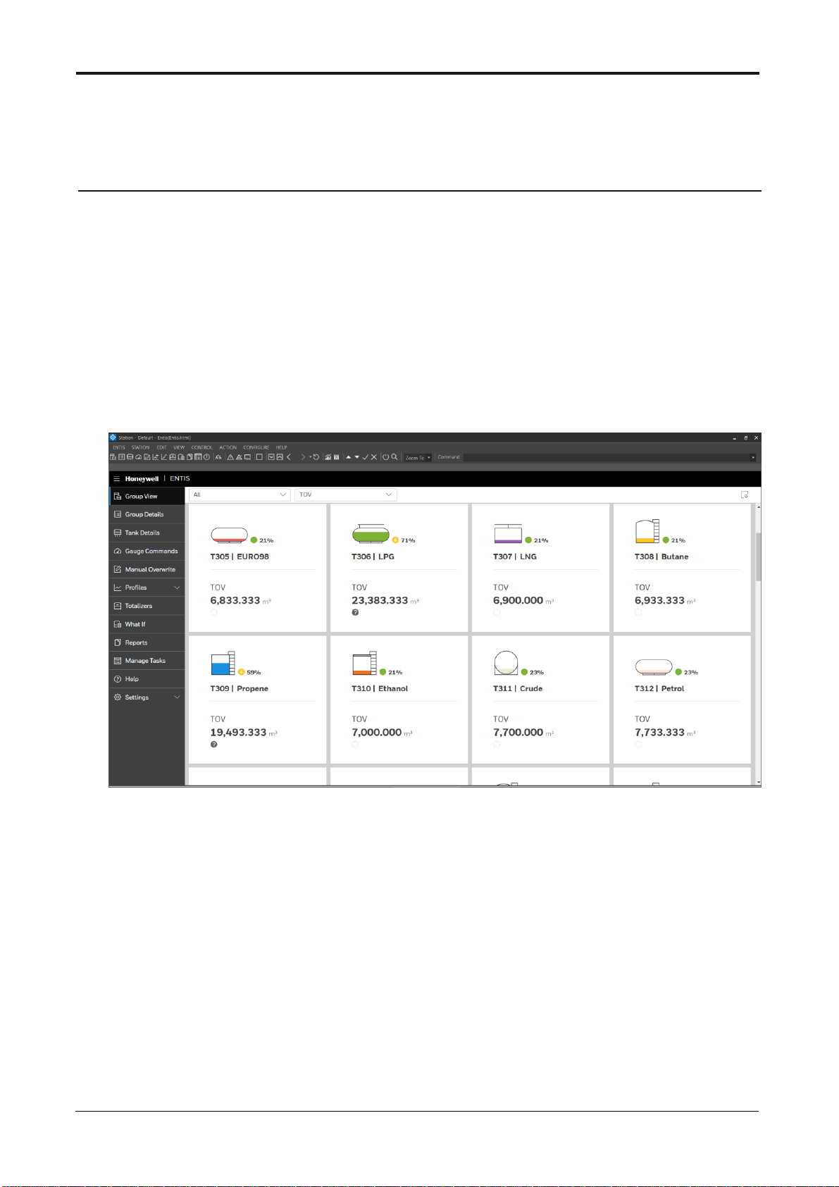
GROUP VIEW
The Group View display shows a group of Tanks with smaller images. All of the
images include a bar graph in which the height is an indication of the amount of
product in the tank, and the % level beside the tank is the product level available
in the tank. The color of the bar graph is per the product’s configured color.
The Tank icons are configurable by Tank. (that configuration is done in the
CIU888 Service tool)
The TOV value is displayed by default, with other entity selections available from
the second selector from the left (above the tank panels).
Figure 7: Group View
How to select the Group View display
1. Group View is the default display when ENTIS is started. You can also
access the Group view display from the menu, or from the icon in the
toolbar.
2. Select the desired group from the Group selection dropdown box.
3. Select the desired entity. The default entities are: TOV, Product Level,
Product Temperature and Water Volume.
Page 25

ETDOC-X615–R120.1 ENTIS R.120.1 User’s Manual 17
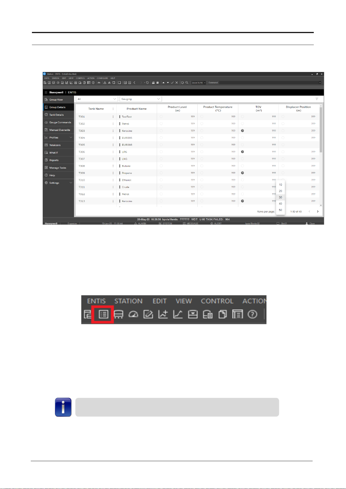
GROUP DETAIL
The Group Detail display show tank inventory data for multiple Tanks in a tabular
format. Tanks are organized in rows, while the entities are displayed in columns.
In addition, this display enables the user to make use of additional functionality
such as the Delta column (licensed option). Dimensions are user-definable and
displayed in the column header.
The user can create their preferred views via the Manage Views dialog.
Display layout
The display presents Tank data in a tabular format. The data displayed on the
grid depends on the selected view. Both values and - if applicable - statuses, are
displayed. Clicking the mouse on the column header will sort the selected
column. Multi column sorting is available by holding the Shift button and selecting
multiple column headers. A blue line on the column header will indicate that it is
sorted, with the blue line position indicating if the sort is ascending (top) or
descending (bottom).
A user definable number of columns, measured from the first column, can be
identified as fixed columns. Fixed columns do not scroll horizontally. The user can
select the number of rows they want to view on a page and toggle between them
via ‘Previous’ and ‘Next’ buttons.
The user can also filter the rows by using ‘Filter’ button where they can select the
column where filter should be applied and set the parameteres of filtering
accordingly.
Page 26
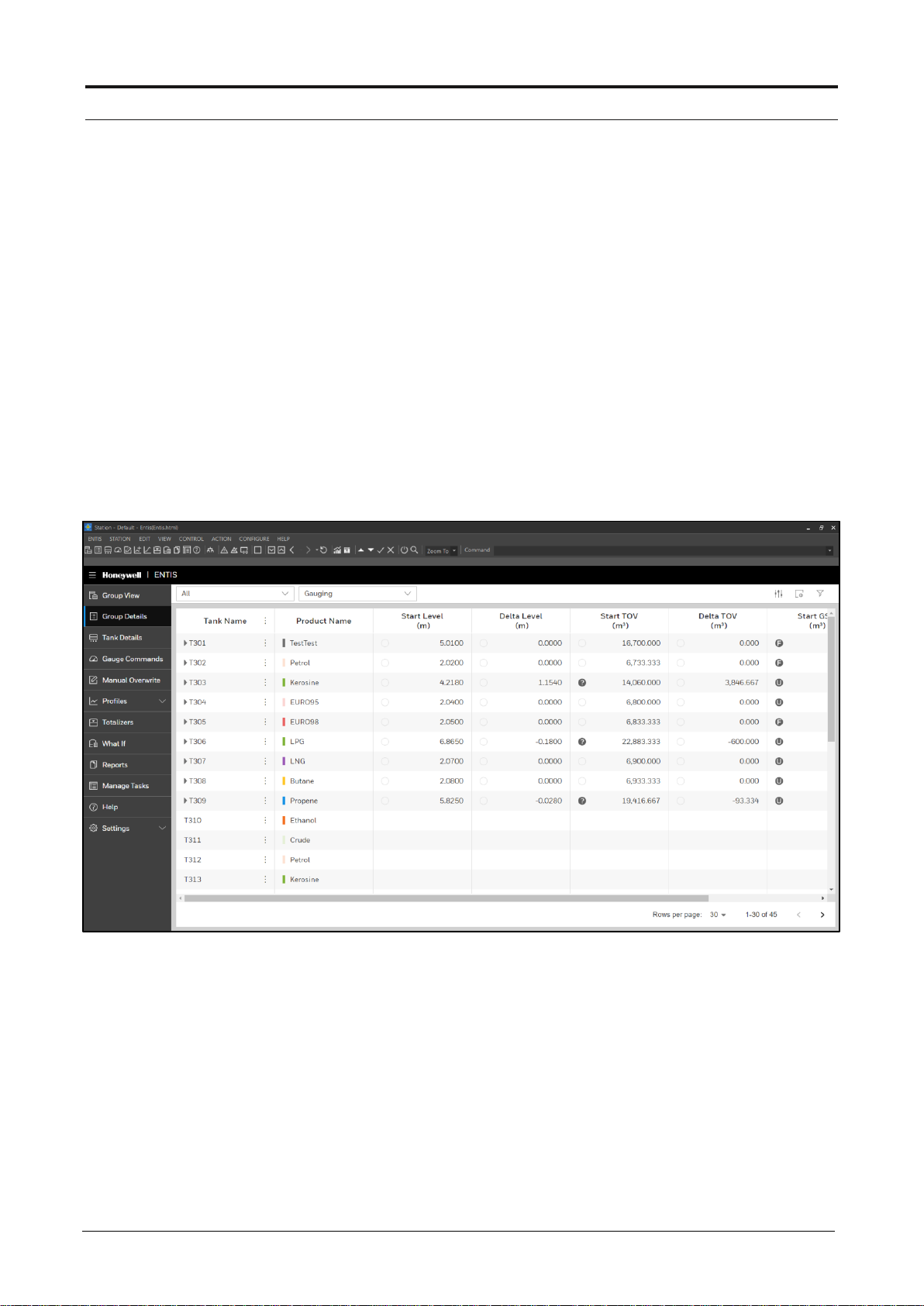
Group Detail
18 ENTIS R.120.1 User’s Manual ETDOC-X615–R120.1
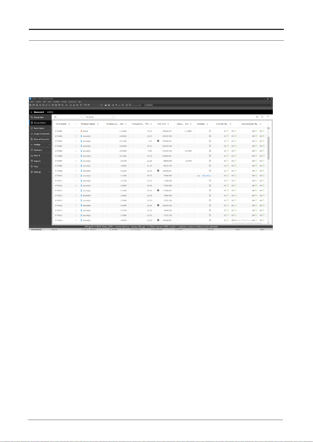
Figure 8: Group Detail
Opening the Group Detail Display
1. Click on the ‘Group Detail’ menu item, or the ‘Group Detail’
icon in the tool bar
2. The ‘Group/Tank’ display will appear
3. Select a Group from the dropdown combobox
4. Tank data will appear in the table
5. ‘All’ indicates that all the tanks will be shown
6. Change the View from the the view dropdown
Column width: The current size is stored whenever the user selects
another view, or the window is closed.
Page 27

Group Detail
TDOC-X615–R120.1 ENTIS R.120.1 User’s Manual 19
Delta column
The Delta column displays the difference between the actual value and the start
value. This feature enables an operator to verify tank operations with real-time
data. Delta values are available for GOV, TGSV, Total Mass, NSV, Level, GSV
and TOV.
The Delta column is only available in the Group Detail display.
The column can be enabled via the Define View dialog.
When the Delta column is available in Group Detail, a click on the Delta column
header (the horizontal ellipses) gives the following context menu:
Figure 9: Delta Column
Page 28
Group Detail
20 ENTIS R.120.1 User’s Manual ETDOC-X615–R120.1
Selecting a Delta Column
Clicking on the horizontal ellipses on the delta tank entity gives the following
menu:
Start Tank When clicked, the delta calculation for the selected tank (row) will be
started or restarted
Stop Tank When clicked, the delta calculation for the selected tank (row) will be
stopped and cleared
Start Group When clicked, the calculation for a group of tanks is started
Stop Group When clicked, the calculation for a group of tanks is stopped and
blanked
Delta Report The delta values will be printed in form of report
Figure 10: Delta Column Group
Page 29
Group Detail
TDOC-X615–R120.1 ENTIS R.120.1 User’s Manual 21
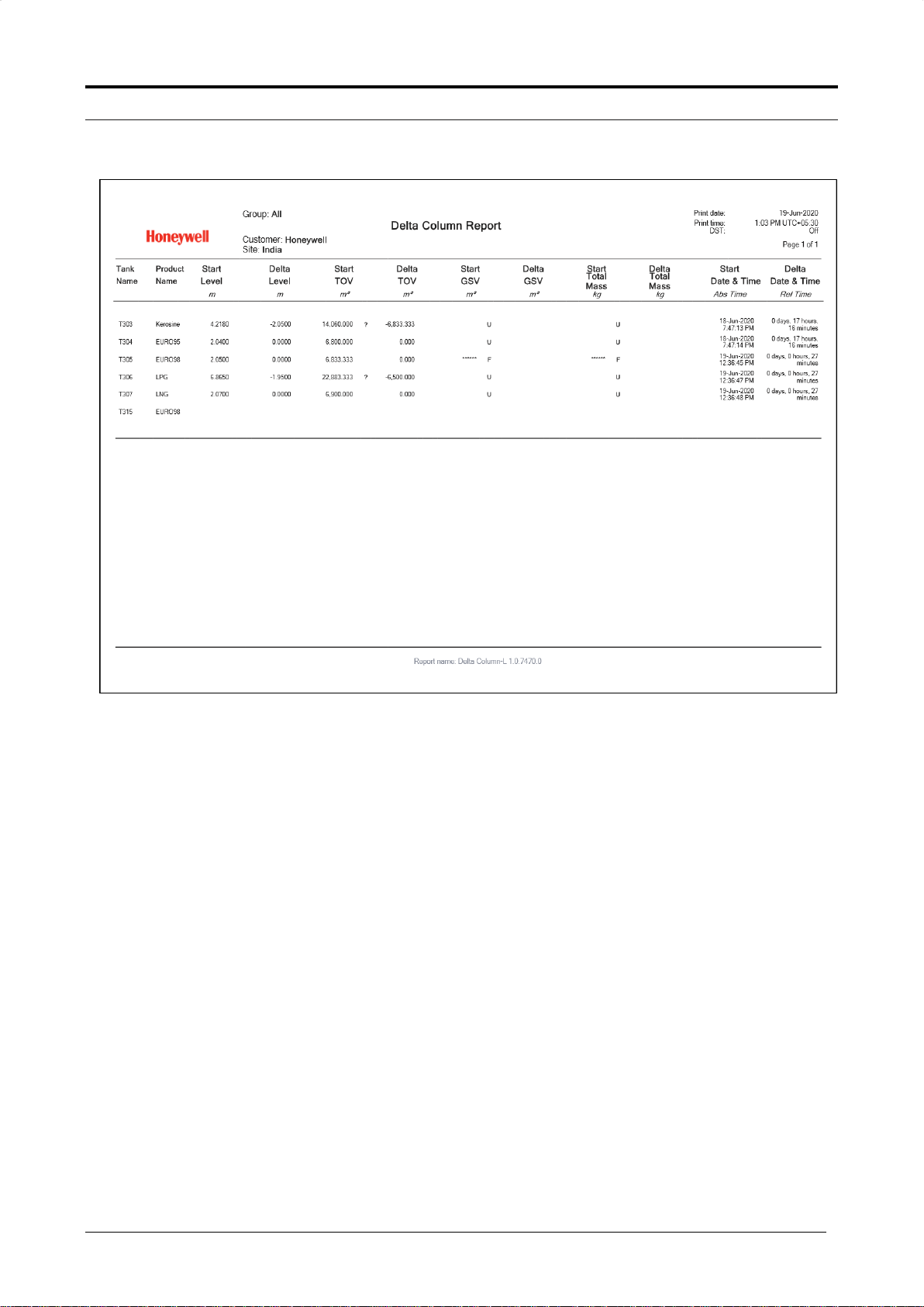
Figure 11: Delta Column Report
Page 30
Group Detail
22 ENTIS R120.1 User’s Manual ETDOC-X615–R120.1
Critical / Operation PAL Column
This column can be used to display PAL statuses in the Group Detail display.
A Critical PAL corresponds with Urgent priority alarms and an Operational PAL
with High and Low priority alarms.
Figure 12: Alarm Column
Page 31

Group Detail
ETDOC-X615–R120.1 ENTIS R120.1 User’s Manual 23
Selecting an Alarm column from Group Detail
To view an alarm, the columns must be added through the “Manage View” dialog
in Group Detail.
1. Go to ‘Manage View’ from Group Detail
2. Select Critical PAL and Operational PAL columns from the Available Entity list.
3. Click on the Ok button
Figure 13: Alarm Column Views
Page 32

Group Detail
24 ENTIS R120.1 User’s Manual ETDOC-X615–R120.1
4. When the View is selected in Group detail, the selected
columns will be available in the display.
Figure 14: Group Detail Alarm Column
Hi and HiHi alarms with Urgent priority are indicated in the Up
arrow from the Critical PAL field.
Lo and LoLo alarms with Urgent priority are shown in the
Down arrow from Critical PAL.
Hi and HiHi alarms with High or Low priority are shown in the
Up arrow from Operational PAL
Lo and LoLo alarms with High or Low priority are shown in the
Down arrow from Operational PAL
Page 33

Group Detail
ETDOC-X615–R120.1 ENTIS R120.1 User’s Manual 25
The next screenshot shows an example in Group Detail when a High alarm is
active.
Figure 15: Alarm Column HA
When the alarm is acknowledged, the tooltip is updated
Figure 16: Alarm Column HA Ack
Page 34

Group Detail
26 ENTIS R120.1 User’s Manual ETDOC-X615–R120.1
Low alarms are indicated with the “down” arrow; in the next screenshot an active
Low alarm with Low priority and one with Urgent priority is shown.
The number indicates the number of alarms for this type.
Figure 17: Alarm Column LA
Page 35

Group Detail
ETDOC-X615–R120.1 ENTIS R120.1 User’s Manual 27
Remark Column
This column allows the user to enter additional text in the Remarks field. The text
can be entered by a left mouse click on the edit icon. See example below. This
field is only available on the Group Detail display.
Figure 18: Remarks Column
Page 36

Group Detail
28 ENTIS R120.1 User’s Manual ETDOC-X615–R120.1
Selecting the remark column from Group Detail
The remark columns must be added through the “Manage View”
option in Group Detail.
Figure 19: Remarks Views
1. Select Manage View from Group Detail
2. Select the Remark column from the Available Entity list.
3. Click on the Ok button
4. Select the View in Group detail screen
5. Left mouse click on remark field edit icon for selected tank
6. Enter user name and save remarks
7. Remark will be available for the selected view in Group Detail
Page 37

Group Detail
ETDOC-X615–R120.1 ENTIS R120.1 User’s Manual 29
Adding a remark from group detail
1. Remark can be edited by a left mouse click on the edit icon.
2. Upon clicking, the remarks column is expanded as shown in the screenshot
below.
Figure 20: Remarks Views edit
3. The user can add their username and remarks, and click Ok. The remark is
saved as history with username, date, time and the remark.
Figure 21: Remarks Views with history
Page 38

30 ENTIS R120.1 User’s Manual ETDOC-X615–R120.1
TANK DETAIL
Tank Detail is a display that shows all measured and inventory data for one
particular tank.
The screen provides an excellent overview of all relevant data and is updated
continuously. It also displays the product level in % occupancy, and second level
in the case where dual guages are connected.
To change the tank being viewed, a combo box is available to change tank
selection. This combo box shows all the tanks available in the selected group.
Data presentation
1. Measured data is always presented as green text.
2. Calculated data, such as inventory data is presented as black text.
3. Status and Validity information is available in circular indicators.
4. Units are shown in black after the status and validity symbols.
Display layout
The tank detail window consists of two main parts:
Toolbar
The toolbar shows a ‘Tank Detail’ icon at the left-hand side. The dropdown box
allows you to choose and view another tank in the same group. Tooltips are
available for tank oriented tasks.
Graphical pane
Display of entities (measured and calculated) belonging to the selected tank.
The time to fill is calculated from available TOV/flow TOV. The time to empty is
calculated from available room/flow TOV
Page 39

Tank Detail
ETDOC-X615–R120.1 ENTIS R120.1 User’s Manual 31
Tank detail window for fixed roof tanks
This window selection is based on tanks with no corrections.
Figure 22: Tank Detail
Page 40

Tank Detail
32 ENTIS R120.1 User’s Manual ETDOC-X615–R120.1
Tank detail window for fixed & floating roof tanks
The window selection is based on tanks with S&W and floating roof corrections.
Figure 23: Tank Detail Floating
Page 41

Tank Detail
ETDOC-X615–R120.1 ENTIS R120.1 User’s Manual 33
Tank detail window for spheres
The window selection is based on tanks with vapour room corrections (gas
volume calculations).
Figure 24: Tank Detail Sphere
Page 42

Tank Detail
34 ENTIS R120.1 User’s Manual ETDOC-X615–R120.1
Selecting the Tank Detail display
Proceed as follows:
1. Click on the ‘Tank Detail’ option from the tool bar.
Figure 25: Tank Detail Icon
2. You can also click on the ‘Tank Details’ option available on the
left side menu.
3. The ‘Tank details’ window will appear.
4. Select a group from the tree view. The selected group will be
displayed in the tool bar
5. Individual tanks can be selected from the drop down combo
box in the tool bar, or from the ‘Group/Tank’ window.
Page 43

ETDOC-X615–R120.1 ENTIS R120.1 User’s Manual 35
GAUGE COMMANDS
Modern gauges often support special commands and/or functions. These
commands can be used, for example, to ‘Block’ the displacer at a certain level, or
for testing alarm contacts remotely.
The available command and function can be dependent on the type of gauge or
the application.
The Gauge Command display for ENTIS is ‘gauge aware’. It shows the user an
icon corresponding to the gauge type, and shows which functions are enabled for
that particular gauge.
Tab layout
Figure 26: Gauge Commands
1. Select the group
2. Select the tank
3. Select one of the available command tab
4. Click on the desired function and press Apply
Page 44

Gauge Commands
36 ENTIS R120.1 User’s Manual ETDOC-X615–R120.1
How to issue a Dipping Command
Figure 27: Dipping Command
Proceed as follows:
1. Click on the ‘Gauge Commands’ tab.
The Dipping section will be displayed by default
2. Select a group from the dropdown.
The selected group will be displayed in the tool bar
3. Individual tanks can be selected from dropdown.
4. Select the command you want to issue from the check boxes:
Density dip
Select to execute a density dip. This command only applies to
854 type gauges with the density option. Select one of the two
radio buttons. Density can be executed in two ways:
Downwards
Upwards
Water dip
Select to execute a water dip
Page 45

Gauge Commands
ETDOC-X615–R120.1 ENTIS R120.1 User’s Manual 37
How to issue a Displacer Command
Figure 28: Displacer command
Two different displacer commands can be issued:
1. Go to the ‘Displacer’ panel of the ‘Gauge Commands’ tab
2. Select a group from the dropdown.
The selected group will be displayed in the tool bar
3. Individual tanks can be selected from dropdown.
4. Select the command you want to issue by means of the radio buttons
Table 2: Displacer Commands
Radio Button
Comman Description
Test
The level gauge will be set in lock test for approx. 1 minute,
followed by an unlock command
Lock Test
When selecting this radio button, a data entry field will be
enabled
Lock Test at
Enter the Lock test value
Auto Unlock
When selecting this check box, the displacer will be
lowered automatically after reaching the value entered in
the data entry field.
Verify Calibration
When selecting this radio button, the displacer will be
raised until the CA setting in the servo gauge is reached
Page 46

Gauge Commands
38 ENTIS R120.1 User’s Manual ETDOC-X615–R120.1
How to issue a Test Gauge Alarm
Figure 29: Tank Gauge Alarm
Proceed as follows:
1. Go to the ‘Test gauge alarm’ section of the ‘Gauge
Commands’ tab
2. Select a group from the dropdown.
The selected group will be displayed in the tool bar
3. Individual tanks can be selected from dropdown.
Alarm tests: Click on one or more alarms you want to test
This command can be used to test the alarm settings in the radar
gauge. The alarm settings to be tested are HiHi, Hi, Lo, LoLo in any
combination
Page 47

Gauge Commands
ETDOC-X615–R120.1 ENTIS R120.1 User’s Manual 39
How to cancel commands
An unlock command can be sent to the level gauge in order to
cancel the command in progress.
Running Dipping Commands
This window shows the progress of a dipping command. The progress indicator is
used to show the percentage of completion of the issued command.
The progress of the following dipping commands can be monitored:
Density dip
Water dip
Tab layout
At start-up, the Tank name, dipping command and original displacer position are
shown. After start up, the actual displacer position is displayed
Figure 30: Displacer
Title bar Displays the selected tank name and the issued command
Displacer Position
This group box shows the displacer position:
Original - The level at start up
Actual - The actual position of the displacer
Page 48

Gauge Commands
40 ENTIS R120.1 User’s Manual ETDOC-X615–R120.1
Running Displacer Commands
This window shows the actual displacer position during a Lock test or
Verify calibration test command. These commands can only be
issued for servo level gauges.
Tab layout
At start-up, the window shows the tank name and the displacer
command in the title bar.
The group box shows the ‘Original’ displacer position (level at start-
up) and the ‘Actual’ position. In addition to the level values the status
and the dimension are displayed.
Figure 31: Displacer
Page 49

Gauge Commands
ETDOC-X615–R120.1 ENTIS R120.1 User’s Manual 41
Scheduling Gauge Command
This option is displayed at the bottom of left hand panel on the ‘Gauge
Commands’ screen. This feature allows the user to send automated commands
to gauges at a given time.
The user can create a task and schedule gauge commands for different intervals
like daily, weekly, monthly etc., starting at a specific time. The tasks created here
are shown on ‘Manage Tasks’ screen.
Once the gauge command is scheduled, it will be executed at the scheduled
time.
Figure 32: Schedule Command Screen
Page 50

Gauge Commands
42 ENTIS R120.1 User’s Manual ETDOC-X615–R120.1
How to schedule a gauge command
Choose the specifications of the gauge command that needs
to be scheduled. Then click on Schedule button.
Task Name : This is user defined field which defines name of
the task.
Starts at : User can choose when the task execution will start.
Repeat : If the task has to be executed only once, ‘Never’
should be selected. If is a repeated task, ‘Always’ should be
chosen.
Select Cycle : User can choose the frequency of the task
from below available 3 options. The option will only be
enabled when ‘Repeat’ is ‘Always’.
1. Interval : User can give any interval in hh:mm.After the
‘start at’ time, this task will be executed continuously at
the given interval.
2. Weekly : The user can choose the days. Every week this
task will be executed on the selected days, and the time
provided in ‘start at’.
3. Monthly : The user can choose the dates in a month.
Every month this task will be executed on the provided
dates, and the time provided in ‘start at’.
Never: User can opt for scheduling the gauge command
only once without repeating it.
Figure 33: Scheduling screens
Page 51

ENTIS R.120.1 User’s Manual ETDOC-X615–R120.1 43
MANUAL OVERWRITE
This display allows the user to manually overwrite tank data. The ’Manual
Overwrite’ display can, for example, be used to overwrite an invalid entity, or to
enter the value of an entity that is not being scanned or for which automatic
measurement has stopped scanning (formerly known as ‘killed’).
This display supports basically two actions:
Stop scanning an entity (formerly known as ‘kill’)
Resume scanning an entity (formerly known as ‘resurrect’)
Enter manual data for an entity
Display Layout
The ‘Manual Overwrite’ window consists of two main parts:
The entity selection pane (left)
The entity overwrite area (right)
All Entities
This panel shows a tree with all available entities.
Figure 34: Manual Overwrite
Page 52

Manual Overwrite
44 ENTIS R120.1 User’s Manual ETDOC-X615–R120.1
Entity Pane
The entity overwrite area consists of four fields.
Table 3: Entity Fields
Entity Name
This fields shows the selected entity
Stop Scan
This check box indicated whether the entity is not scanning. Marked
means not scanning (or stopped). This check box is not present by
every tank entity.
Current Value
This column may contain a mix of data entry fields, combo boxes
and check boxes depending on the entity being displayed. The
entity value will be shown if:
- the entity status is set to manual. (with manual data icon)
- the entity has actual data. (with actual data icon)
If the entity has stopped scanning, it will be displayed with killed
icon and blank value
Dimension
Shows the current dimension
Performing a Manual Overwrite
1. Click on the ‘Manual Overwrite’ icon.
2. Click on the tree icon at the left site in the tool bar.
The ‘Group/Tank’ window will appear.
3. Select a group from the tree view.
4. Select the tank you want to overwrite.
5. Select the entity you want to overwrite from the ’All Entities’
pane
6. Click on the ‘Stop Scan’ check box of the selected entity in
the right pane means killed.The ‘Current value’ field will be
enabled.
7. Click on the ‘Current value’ field.
8. Clear the field.
9. Enter the manual value.
Page 53

Manual Overwrite
ETDOC-X615–R120.1 ENTIS R120.1 User’s Manual 45
10. Click on apply.
Figure 35: Manual Overwrite Parameter
Before you begin entering data into the currently selected entity field,
the field background will be white. After entering the value the
background changes to yellow to indicate that you have made a
change and not yet saved it.
If you want to save the entered values click on the Apply button.
The entities Dobs, Tobs and Hydro correction have a close relation. In
the entity tree they are put on one line. In the data area they are
always shown together (3 lines) but can be edited individually.
However Dobs and Tobs must be edited as a pair.
When data of an entity has been changed but not saved (Apply) and
another entity or tank is being selected then a popup windows requests
the user what is required: either cancel the changed data or apply it.
Page 54

Manual Overwrite
46 ENTIS R120.1 User’s Manual ETDOC-X615–R120.1
The GSV calculation type combo box only shows the calculation types that
support the Product Reference Temperature that has been configured for
the selected tank. The Product Reference Temperature cannot be
overwritten manually but must be configured in the CIU 888 with ENTIS
The entities GSV Calc type and Product Code have a close relation. When
a GSV Calc type is selected that does not support the currently selected
Product Code, a pop-up message will advise other valid choices for the
Product Code. The other way around, when a Product Code is selected
that does not support the currently selected GSV calculation type, a pop-up
message will advise other valid choices for the GSV Calculation type. If the
advice is ignored, the GSV calculation type will change to “Undefined” after
applying the manual overwrite. For diagnostic purpose, a tooltip text on the
GSV Calculation type column in the Group Detail task reveals the GSV
calculation type code when an “Undefined” combination of GSV Calculation
type, Product Code and Product Reference Temperature has been
configured.
How to cancel a Manual Overwrite
1. Click on the ‘Manual Overwrite’ icon
2. Click on the tree icon at the left site in the tool bar. The ‘Group/Tank’ window
will appear
3. Select a group from the tree view
4. Select the tank you want to cancel a manual overwrite
5. Select the entity from the ’All Entities’ pane
6. Click on the ‘Resume Scan’ check box of the selected entity in the right pane.
Unchecked means not scanning
Page 55

ENTIS R.120.1 User’s Manual ETDOC-X615–R120.1 47
PROFILES
The primary Profiles usage is to create profiles for a selected tank and to show a
graphical display of the density and/or temperature variation of the product in a
tank.
The user has a number of options to generate profiles such as:
Density profile:
Used to measure the observed density.
The 854 or 954 servo gauge is commanded to start a density measurement.
The density measurement moves the displacer through the product in the tank,
and determines the density at 10 equidistant points if a 854 gauge is connected,
and up to 50 equidistant points if a 954 gauge is connected.
Temperature profile:
VITO probe connected to Radar or servo gauges will allow user to have
temperature profiles on ENTIS, Number of temperature points configured in VITO
associated at different level’s will decide Average temperature in profile graph
Density and temperature profile:
Determines a density and temperature profile for different product types in the
tank.
Combined profile:
Measures the water interface, and determines a density profile.
Combined profile (Incl. Temperature)
Measures the water interface and determines a density and temperature profile.
Interface Profile
An Interface profile command starts a density measurement between two specified
levels.
The interface profile measurement moves the displacer through the product in the
tank and determines the density at 10 equidistant points if an 854 gauge is
connected, and up to 50 equidistant points if the 954 gauge is connected between
the two specified levels.
Page 56

Profile
48 ENTIS R120.1 User’s Manual ETDOC-X615–R120.1
Display layout
Figure 36: Create Profile
This display has the following sections:
At the upper part, tank data is displayed.
In the middle part, the selection can be made for the type of profile to be
created.
At the bottom part, a progress window is displayed for each profile
currently in progress.
How to create a profile:
1. Select Profiles | Create Profile
This opens the Create Profile screen.
2. When using a user defined filename, uncheck the checkbox “Automatic
Filename Generation”. This gives you the opportunity to enter your own
filename in the edit box. By default, the checkbox is checked.
In that case the filename is:
[tankname]_yyyy-mm-ddThh-mm-ss.json
Page 57

Profile
ETDOC-X615–R120.1 ENTIS R120.1 User’s Manual 49
3. Select the required profile type (Density, Combined, Temperature, Interface); For
an Interface profile, enter the Highest and Lowest level.
4. Select advanced data Upwards or Downwards (only for Density and Interface
profile) and “Temperature profile included” (for Density, Combined and Interface)
5. Select advanced data Upwards or Downwards (only for Density and Interface
profile) and “Temperature profile included” (for Density, Combined and Interface)
6. Click on Start.
The profile command will be sent to the CIU888;
7. When the profile is ready, this will be indicated by a popup dialog:
Figure 37: Profile ready
Page 58

Profile
50 ENTIS R120.1 User’s Manual ETDOC-X615–R120.1
Viewing a profile:
1. Select Profiles | View Profiles
This opens the View Profiles screen
2. Click on Browse Profiles
3. In Filters, select whether you want to see all profiles, or only
certain types (Density, Combined, Temperature, Interface)
4. In Filters, update the date range as required
(by default, it shows the profiles from the last week)
5. From the list of profiles, select the profiles you want to view.
6. Click Open:
The selected profiles are displayed.
Profile screen examples
Temperature Profile
Figure 38: Temperature profile
Page 59

Profile
ETDOC-X615–R120.1 ENTIS R120.1 User’s Manual 51
Density Profile
Figure 39: Density Profile
Interface Profile
Figure 40: Interface Profile
Page 60

Profile
52 ENTIS R120.1 User’s Manual ETDOC-X615–R120.1
Density + Temperature Profile
Figure 41: Density and Temperature profile
Density Profile (50 Density points)
Figure 42: Density profile
Page 61

ETDOC-X615 – R120.1 ENTIS R120.1 User’s Manual 53
TOTALIZER
Totalizers offer an easy way to totalize and view the contents of a group of tanks.
It totalizes the different parameters of the available tanks in a group, such as
GOV, GSV, TGSV, Total Mass, TOV and Available GOV..
Figure 43: Totalizer
Figure 44:Totalizer_All
Page 62

Group Totalizer
54 ENTIS R120.1 User’s Manual ETDOC-X615 – R120.1
How to select the Group Totalizer
Proceed as follows:
1. Click on the ‘Group Totalizer’ icon.
Figure 45: Totalizer Icon
2. Click on the tree icon at the left site in the tool bar.
3. The ‘Group/Tank’ window will appear.
4. Select a group from the tree view. The selected group will be displayed in
the tool bar.
5. Other groups can be selected from the combo box in the tool bar or from
the ‘Group/Tank’ window.
Page 63

ETDOC-X615 – R120.1 ENTIS R120.1 User’s Manual 55
WHAT IF
What if (tank calculator) .. is a predictor tool that calculates and tells us values of
other parameters, based on the custom input values of points.
1. Click on What If icon from menu toolbar
Figure 46: What If
Page 64

What If
56 ENTIS R120.1 User’s Manual ETDOC-X615 – R120.1
Tab layout
On What-If screen, choose the desired group and tank from the drop down.
Figure 47: What – If layout
Page 65

What if
ETDOC-X615 – R120.1 ENTIS R120.1 User’s Manual 57
How to use the calculator
1. Start the Tank Calculator from the toolbar of the ENTIS
2. Select a Group/Tank
3. The Tank Calculator always starts up with the actual inventory data at that
moment
4. The Start screen will pop up
5. All white fields are data entry fields and their contents can be modified.
Figure 48: What – If Start
6. The system will calculate other values and display them.
7. To restore values to real time values coming from CIU, click on Reload
Data.
Page 66

What If
58 ENTIS R120.1 User’s Manual ETDOC-X615 – R120.1
Figure 49: What – If Reload
Page 67

ETDOC-X615 – R120.1 ENTIS R120.1 User’s Manual 59
REPORTS
The Reports display makes it possible to print out reports in pre-defined templates. A
user can preview and print Tank Detail and Group Detail reports from this display.
The tank data displayed in the reports consists of the last available measured and
inventory data received from the gauge. It also displays the second level when dual
gauges are connected.
Figure 50: Reports
Report Printing
The Report printing window consists of four main parts:
The Browse Reports
The type of report combo box
The tank/group combo boxes
The template combo box
Page 68

Reports
60 ENTIS R120.1 User’s Manual ETDOC-X615 – R120.1
Type of Reports
Select one of the report types from the combo box.
The following Options are enabled depending of the selected report:
Group/Tank Two combo boxes used to select a group or a tank name
Template Depending on the selected type of report, the ‘Template’ combo box will
list the available templates
How to select Reporting
1. Click on the ‘Reporting’ icon.
Figure 51: Reporting icon
2. You can also select ‘Reports’ from the options available on left side of the
screen.
Figure 52: Tank detail report
3. Select Tank Details or Group Details from the combo box.
4. Select a Template.
5. Click on Preview.
Page 69

Reports
ETDOC-X615 – R120.1 ENTIS R120.1 User’s Manual 61
Command buttons
Prints the selected report
Shows a preview of the selected report type on screen
Browse Reports
This option will be displayed on the top of the ‘Reports’ screen. All the saved PDF
files can be selected for viewing again.
Page 70

Reports
62 ENTIS R120.1 User’s Manual ETDOC-X615 – R120.1
Filters
A combo box is available to select the report type, listing only the reports belonging
to that report type. The calendar option allows the user to select the date range.
Figure 53: Browse Reports
Page 71

Reports
ETDOC-X615 – R120.1 ENTIS R120.1 User’s Manual 63
Report Scheduling
This option is displayed at the bottom of the ‘Reports’ screen. This feature allows the
user to schedule automated reports.
Figure 54: Schedule report
The user can create a task and schedule reports for different intervals like daily,
weekly, monthly. The tasks created here are shown on ‘Manage Tasks’ screen.
Once the report is scheduled, it will get automatically generated (and saved) at the
Reports path at the scheduled time.
Page 72

Reports
64 ENTIS R120.1 User’s Manual ETDOC-X615 – R120.1
How to schedule a report
Choose the specifications of the report that needs to scheduled then click on
Schedule button.
Make the following selections for the scheduled report.
Task Name : This is user defined field which defines name of the task.
Starts at : User can choose when the task execution will start.
Repeat : If the task has to be executed only once, ‘Never’ should be
selected. If it is a repeated task, ‘Always’ should be chosen.
Select Cycle : User can choose the frequency of the task from below
available 3 options . It will be enabled only when repeat is chosen as ‘Always’
1. Never : User can opt for scheduling the reports only once without
repeating it.
2. Interval : User can give any interval in hh:mm, after ‘start at’ time this
task will be executed continuously after the given interval.
3. Weekly : User can choose the days, every week this task will be
executed on the provided days and time provided in ‘start at’.
4. Monthly : User can choose the dates in a month, every month this
task will be executed on the provided dates and time provided in ‘start
at’.
Figure 55: Schedule report screens
Templates
The format of a printout is defined by templates. ENTIS supports following
templates:
Page 73

Reports
ETDOC-X615 – R120.1 ENTIS R120.1 User’s Manual 65
Tank Detail
Group Detail – Crudes, CTL, General Product, Inventory, Measured
What If
Delta Column
Report Templates
Example of a group detail printout.
Figure 56: Group detail report
Page 74

Reports
66 ENTIS R120.1 User’s Manual ETDOC-X615 – R120.1
Tank Details
Example of a tank detail printout.
Figure 57: Tank detail
Page 75

Reports
ETDOC-X615 – R120.1 ENTIS R120.1 User’s Manual 67
Delta Column
Figure 58: Delta column report
Page 76

Reports
68 ENTIS R120.1 User’s Manual ETDOC-X615 – R120.1
What If ..
Example of a What If .. printout.
Figure 59 - What if .. report
Page 77

Reports
ETDOC-X615 – R120.1 ENTIS R120.1 User’s Manual 69
Page 78

70 ENTIS R120.1 User’s Manual ETDOC-X615 – R120.1
MANAGE TASKS
Once a Gauge Command/Reporting task is scheduled, users can view the
list of tasks on this window.
Users can edit the schedule of the tasks and - if needed - tasks can also
be deleted from here.
Figure 60: Manage Tasks
User can open the Manage Tasks screen by clicking on ‘Manage
Tasks’ icon from the experion toolbar or by clicking on the
navigation menu on the left.
The display will show the list of tasks scheduled, with their task
name, type (Reporting/Gauge Commands), and Edit and Delete
buttons.
Page 79

Manage tasks
ETDOC-X615 – R120.1 ENTIS R120.1 User’s Manual 71
How to edit/delete a task
1. Click on the edit button in front of the task.
A scheduling screen will popup.
Figure 61: Scheduling screen
2. Change the details of the schedule and click ok.
The task will be updated.
3. To delete, click on the delete button in front of the task.
A confirmation dialog will pop up.
Figure 62: Confirmation Dialog
4. Click on ‘Yes’ to delete the task.
Page 80

72 ENTIS R120.1 User’s Manual ETDOC-X615 – R120.1
HELP
HELP
This Display opens the ‘ENTIS User Guide’.
Figure 63: Help
How to select Help
1. Click on the ‘Help’ icon from the toolbar.
Figure 64: Help icon
2. You can also select ‘Help’ from the options available on left side of
the screen.
3. On clicking either of the 2 options, the ‘ENTIS User Guide’ opens
on the right panel of the ENTIS screen.
Page 81

ETDOC-X615–R120.1 ENTIS R120.1 User’s Manual 73
SETTINGS
ALARMS
Age Alarms
The system periodically checks the tank record time stamps against the
system clock. If the difference exceeds a predefined value, an AGE alarm
is generated. Aging values are checked on a per tank basis, so AAL’s are
generated for each tank separately.
Foreground
A foreground age alarm is generated
Background
A background age alarm is generated
Deviation Alarms
The deviation alarm is an alarm that will be raised when Product level 1
and Product Level 2 on a tank deviates from each other. The deviation
alarm is only applicable on tanks with dual gauges. With the switch on the
Alarm Setting display, you can enable or disable the deviation alarm for all
tanks that have dual gauges.
Difference value
The difference value is the absolute value difference between Product
Level 1 and Product Level 2. The difference alarm will only occur if both
gauges are measuring level, and are not in a failed state.
Page 82

Settings
74 ENTIS R120.1 User’s Manual ETDOC-X615–R120.1
Figure 65: Alarm Settings
Page 83

Settings
ETDOC-X615–R120.1 ENTIS R120.1 User’s Manual 75
Product Color Code
Each product will have an associated color which can be customized.
The product names for color coding are not case-sensitive.
Figure 66: Product Color Code
The user can also set the RGB color for that product by clicking on the ‘+’
as shown below.
Page 84

Settings
76 ENTIS R120.1 User’s Manual ETDOC-X615–R120.1
Clock Sync
The master clock feature synchronizes the ENTIS application and CIU
clocks, with the ENTIS clock serving as the master.
Having the ENTIS and the CIU clocks be synchronized helps ensure that
timestamps on alarms, events and operational data are consistent.
Figure 67: Clock Sync
Manage Files
ENTIS generated files can be cleaned up/deleted after a defined number of
days in the below configuration.
The Disable/Enable auto clean up can be applied for auto cleanup of files.
Figure 68: File Cleanup
Page 85

Settings
ETDOC-X615–R120.1 ENTIS R120.1 User’s Manual 77
Reporting
User can set the customized ‘Customer Name’, ‘Site Name’, and
upload a ‘Customer Logo’ here. This information will be reflected in the
Reports header.
Figure 69: Reporting Settings
Page 86

78 ENTIS R120.1 User’s Manual ETDOC-X615–R120.1
HOT STANDBY & REDUNDANCY SUPPORT ENTIS
When ENTIS is licensed and configured for redundancy, after the
occurrence of a server failure, the second system will automatically take
over the lost functionality of its counterpart to become the primary.
The user can also perform a manual switch over using the Server
Redundancy display in Station.
How to perform a manual switch over
Proceed as follows:
1. Login with an account with mngr role access.
2. Select: View | System status | Server redundancy
3. Make sure the Primary and Secondary are synchronized(1).
4. Press Failover
Page 87

Hot Standby & Redundancy Support
ETDOC-X615–R120.1 ENTIS R120.1 User’s Manual 79
5. Press the ‘Yes’ button (top right)
1)
The redundant failover function is provided by Experio. Please refer to the
Experion manual for all details related to this function
Page 88

Hot Standby & Redundancy Support
80 ENTIS R120.1 User’s Manual ETDOC-X615–R120.1
Hot Standby & Redundancy Support (CIU 888)
ENTIS can be enhanced for use in critical applications with hot standby and
redundancy support. Redundancy support can cover the unlikely event of a network
failure, providing sustained and reliable data to your management system. After the
occurrence of an error, the second system will take over the lost functionality.
Following the switchover, all gauge data will be rescanned and recalculated to ensure
the reliability of data.
The operator can also perform the switch over manually, after reviewing on the health
status of the CIU 888.
Page 89

Hot Standby & Redundancy Support
ETDOC-X615–R120.1 ENTIS R120.1 User’s Manual 81
How to Perform Manual Switch Over
Proceed as follows:
1. Click on the ‘Settings tab.
The ‘CIU Status’ tab will appear
2. Click on the ‘CIU Status’ tool bar.
The ‘CIU Status’ window will appear
3. The CIU Status window will show the status of the CIU888 with the
following fields:
CIU Name Name of the CIU 888
Type Primary/Secondary
Health Green if CIU is up and healthy, Red if
CIU is own/ network failure
IP Address The IP Address of the CIU
Status Active/Passive
4. Select hot standby pair of CIUs.
The ‘Switch Over’ button will be enabled.
5. Click on the ‘Switch Over’ button.
The Passive member will become Active and the Active member
will become Passive.
Page 90

82 ENTIS R120.1 User’s Manual ETDOC-X615–R120.1
ALARMS
CONFIGURE ALARMS
Alarms are primarily used to notify operators of conditions that might call
for intervention. Alarms for standard points are specified when you
configure your points in Quick Builder. The standard points of tanks for
which alarms can be configured are given in the table below.
Table 4: Configuration Alarms
Point
Description
_CDObs
The Product Density
_cProductLevel
The Product Level in the tank.
_ProductLevel2
The Product Level 2 in the tank
_cProductTemp
The Product Temperature
_cVapRoomPress
The product vapor pressure
_cVapRoomTemp
The product vapor temperature
_cWaterLevel
The Water Level in the tank
_cWaterVol
The Water Volume
_cProductDRef
The reference density for the Product in the tank.
_FlowTOV
The Total Observed Volume(TOV) of the product per time unit.
_GOV
The Gross Observed Volume(GOV). The GOV is the total
volume of all petroleum liquids and sediment and water,
excluding free water, at observed temperature and pressure
_GSV
The Gross Standard Volume(GSV). The GSV is the total
volume of all petroleum liquids and sediment and water,
excluding free water, corrected by the appropriate volume
correction factor (VCF = CTL) for the observed temperature
and API gravity, relative density, or density to a standard
temperature, and corrected by the applicable pressure
correction factor (Cpl) and meter factor.
_MassLiq
The product volume weight.
_TGSV
The Total Gross Standard Volume(TGSV).
_TotalMass
The product plus vapor volume weight.
_TOV
The Total Observed Volume(TOV)
_GAL
Gauge Alarm
_AALB
Age Alarm Background
_AALF
Age Alarm Fore ground
_MovingStatus
The level moving Status
_TCAL
Tank CRC Alarm
_DAL
Deviation Alarm between Product Level 1 and Product Level 2
on a tank
Page 91

Alarms
ETDOC-X615–R120.1 ENTIS R120.1 User’s Manual 83
How to configure Alarms
To configure an alarm for a point of a tank, follow the steps given below.
1. Type the point name prefixed with the tank name in the
Command text box on top right corner of the station. For
example, if an alarm must be configured for the _cProductLevel
for tank T811, the tank name should be prefixed with the tank
name as shown below.
Press F12. This opens the point configuration screen as shown below.
Figure 70: Configuration screen
3. Click on the Alarms Tab.
Page 92

Alarms
84 ENTIS R120.1 User’s Manual ETDOC-X615–R120.1
The Alarms configuration screen opens.
Figure 71: Alarm Configuration screen
Fill in the details of the alarm for the selected point of the tank.
For more details on how to configure alarms, and to understand the
parameters such as Type, Limit, On Delay etc. please refer to the “About
alarms and events for standard points” section in the Experion Server
and Client configuration guide, EHDOC-X127-en-510A.
Page 93

Alarms
ETDOC-X615–R120.1 ENTIS R120.1 User’s Manual 85
VIEW ALARMS
The Alarms View in Station provides details about each alarm, such as the Date
and time when it has occurred, the asset location, source, condition, priority etc.
Display Layout
Figure 72: View Alarms
Page 94

Alarms
86 ENTIS R120.1 User’s Manual ETDOC-X615–R120.1
How to view Alarms
To view the Alarms page, go to the View menu and click on the Alarms item.
Alternatively, it can be accessed by clicking the Alarms icon on
the tool bar or the Display Alarm Summary icon flashing in red on the status bar.
Understanding the Alarms View
This screen has the following columns.
1. Priority of the Alarm with a visual icon.
This column shows the alarm’s state in symbolic way with a Yellow
triangle or Red square with an asterisk in it. This represents the
priority of the alarm, whether it is a critical, a high, a medium or a low
alarm.
2. Date & Time
Date and Time when the alarm was raised.
3. Location Tag
Location of the Alarm. For ENTIS, it is generally ENTISAsset.
Alarms can be filtered based on location.
This location filter is available above Date & Time column.
4. Source
The point or device that caused the alarm. If the point ID is too long to
be fully displayed in the alarm summary, it will be truncated.
To see the full name, place the mouse pointer over the partial point ID
to display the full point ID.
Page 95

Alarms
ETDOC-X615–R120.1 ENTIS R120.1 User’s Manual 87
5. Condition
The alarm condition.
6. Priority
The priority of the alarm as listed below. The prefix letter indicates the
general priority as listed below.
Critical
Urgent
High
Low
If a number follows the letter, it represents the relative priority within the
general priority. For example, Urgent alarms can vary from U15 (most
urgent) to U00 (least urgent).
7. Description
A description of the alarm. If the description is too long to be fully
displayed in the alarm summary, it is truncated. To see the full
description place the mouse pointer over the partial description to
display the full description.
Description is available in the language choosen by the user.
8. Trip value
The value that triggered the alarm.
9. Live value
The current value. This value is continually updated. If the Format live
value in Alarm Summary using PV Format setting in the Summary
Displays tab of Server Wide Settings is enabled, live values in the
Alarm Summary will be shown in the format configured for point
parameter values. For information, see “Configuring precision values
for point parameters.” Alternatively, two decimal places will be shown.
Page 96

Alarms
88 ENTIS R120.1 User’s Manual ETDOC-X615–R120.1
10. Units
The unit that the value represents, for example ml/s. Please refer
Operators guide available in Help menu or Server and Client configuration
guide in Experion HS in Start Menu for more details on viewing the Alarms
and understanding them in detail.
Page 97

89 ENTIS R120.1 User’s Manual ETDOC-X615–R120.1
EVENTS
Viewing Events
Every event, such as a point status change or an operator action, is stored
in an event database. The event database stores events for a specified
period. Using Event archiving, you can archive these events to a network
file server or to a disk where they can be stored for future retrieval and
reporting. For information on archiving events or restoring events from
archive, see the Experion Operator's Guide, EHDOC-XX80-en-510A.
Page 98

Events
90 ENTIS R120.1 User’s Manual ETDOC-X615–R120.1
How to view events
To view the events summary in Experion station, navigate to
View ->Events->Event Summary menu option on Experion Station as shown in the picture
below.
Figure 73: View Events
Understanding Events View
The Events summary is shown in tabular format with the following columns.
1. Date & Time
The time and date at which the event was received.
2. Location
The tag name of the asset to which the point or device belongs.
3. Source
The point or device that caused the event. If the point ID is too long
to be fully displayed in the event summary, it is truncated. To see
Page 99

Events
ETDOC-X615–R120.1 ENTIS R120.1 User’s Manual 91
the full name, place the mouse pointer over the partial point ID to
display the full point ID.
4. Condition
The event condition.
5. Action
The action, either operator or system generated.
6. Priority
The priority of the event. The prefix letter indicates the general
priority:
Urgent
High
Low
Journal
If a number follows the letter, it represents the relative priority within
the general priority. For example, Urgent events can vary from U15
(most urgent) to U00 (least urgent).
7. Description
A description of the event.
If the description is too long to be fully displayed in the event
summary, it is truncated. To see the full description, place the
mouse pointer over the partial description to display the full
description.
Description is available in the language choosen by the user.
Page 100

Events
92 ENTIS R120.1 User’s Manual ETDOC-X615–R120.1
8. Value
The value of the event.
9. Units
The unit that the value represents, for example ml/s.
10. Operator
The logged in Operator.
Please refer Operators guide available in Help menu or Server
and Client configuration guide in Experion HS Pdf collection in
Start Menu for more details on viewing the Events and
understanding them in detail.
 Loading...