

Page 1

Installation Guide
SmartRadar FlexLine
Page 2

© 2011 - Honeywell International Inc.
Contact Information:
Head Office - Delft, The Netherlands
Honeywell Enraf
Delftechpark 39, 2628 XJ Delft
PO Box 812, 2600 AV Delft
The Netherlands
Tel.: +31 (0)15 2701 100
Fax: +31 (0)15 2701 111
E-mail: enraf.helpdesk@honeywell.com
Website: http://www.honeywell.com/ps
Page 3

Table of Contents SmartRadar FlexLine
Part No.: 4417.760_Rev06 Installation Guide
i
1 General. . . . . . . . . . . . . . . . . . . . . . . . . . . . . . . . . . . . . . . . . .1-1
1.1 Using this Installation Guide . . . . . . . . . . . . . . . . . . . . . . . .1-1
1.2 Related Documents. . . . . . . . . . . . . . . . . . . . . . . . . . . . . . . .1-1
1.3 Trademarks . . . . . . . . . . . . . . . . . . . . . . . . . . . . . . . . . . . . . .1-1
1.4 Contact. . . . . . . . . . . . . . . . . . . . . . . . . . . . . . . . . . . . . . . . . .1-1
2 Safety . . . . . . . . . . . . . . . . . . . . . . . . . . . . . . . . . . . . . . . . . . .2-3
2.1 General. . . . . . . . . . . . . . . . . . . . . . . . . . . . . . . . . . . . . . . . . .2-3
2.2 Safety Conventions. . . . . . . . . . . . . . . . . . . . . . . . . . . . . . . .2-3
2.2.1 Warnings. . . . . . . . . . . . . . . . . . . . . . . . . . . . . . . . . . . . . . . . .2-3
2.2.2 Cautions . . . . . . . . . . . . . . . . . . . . . . . . . . . . . . . . . . . . . . . . .2-3
2.3 Safety Instructions . . . . . . . . . . . . . . . . . . . . . . . . . . . . . . . .2-4
2.3.1 Safety Instructions. . . . . . . . . . . . . . . . . . . . . . . . . . . . . . . . . .2-4
2.3.2 EC Declaration of Conformity (for EU) . . . . . . . . . . . . . . . . . .2-4
2.3.3 Control Drawings for FM & CSA . . . . . . . . . . . . . . . . . . . . . . .2-4
2.3.4 Wireless. . . . . . . . . . . . . . . . . . . . . . . . . . . . . . . . . . . . . . . . . .2-4
2.3.5 Users. . . . . . . . . . . . . . . . . . . . . . . . . . . . . . . . . . . . . . . . . . . .2-4
2.3.6 Additional Information . . . . . . . . . . . . . . . . . . . . . . . . . . . . . . .2-4
2.3.7 Environmental Conditions . . . . . . . . . . . . . . . . . . . . . . . . . . . .2-5
2.4 Liability. . . . . . . . . . . . . . . . . . . . . . . . . . . . . . . . . . . . . . . . . .2-5
2.5 Labels. . . . . . . . . . . . . . . . . . . . . . . . . . . . . . . . . . . . . . . . . . .2-6
2.6 Personal Safety . . . . . . . . . . . . . . . . . . . . . . . . . . . . . . . . . . .2-7
2.7 Warnings and Cautions . . . . . . . . . . . . . . . . . . . . . . . . . . . .2-7
2.7.1 General . . . . . . . . . . . . . . . . . . . . . . . . . . . . . . . . . . . . . . . . . .2-7
2.7.2 Tools . . . . . . . . . . . . . . . . . . . . . . . . . . . . . . . . . . . . . . . . . . . .2-8
2.7.3 Working Environment . . . . . . . . . . . . . . . . . . . . . . . . . . . . . . .2-8
2.7.3.1 Hazardous Zone. . . . . . . . . . . . . . . . . . . . . . . . . . . . . . . . . . . . . . . . 2-8
2.7.3.2 Safe Zone. . . . . . . . . . . . . . . . . . . . . . . . . . . . . . . . . . . . . . . . . . . . . 2-8
2.7.4 Required Skills . . . . . . . . . . . . . . . . . . . . . . . . . . . . . . . . . . . .2-9
2.8 Electrical . . . . . . . . . . . . . . . . . . . . . . . . . . . . . . . . . . . . . . . .2-9
2.8.1 IEC Safety Standards . . . . . . . . . . . . . . . . . . . . . . . . . . . . . . .2-9
2.8.2 Grounding . . . . . . . . . . . . . . . . . . . . . . . . . . . . . . . . . . . . . . . .2-9
Page 4

Table of Contents SmartRadar FlexLine
Installation Guide Part No.: 4417.760_Rev06
ii
2.9 Accordance to Regulations . . . . . . . . . . . . . . . . . . . . . . . .2-10
2.9.1 Device without SmartConn . . . . . . . . . . . . . . . . . . . . . . . . . .2-10
2.9.2 Device with SmartConn. . . . . . . . . . . . . . . . . . . . . . . . . . . . .2-10
2.10 Compliance to FCC, R&TTE, IC . . . . . . . . . . . . . . . . . . . . .2-10
2.10.1 EN 302372-1, ANNEX B . . . . . . . . . . . . . . . . . . . . . . . . . . . . 2-11
3 Product Description . . . . . . . . . . . . . . . . . . . . . . . . . . . . . .3-13
3.1 SmartRadar System Components. . . . . . . . . . . . . . . . . . .3-13
3.2 SmartRadar FlexLine . . . . . . . . . . . . . . . . . . . . . . . . . . . . .3-14
3.2.1 Function. . . . . . . . . . . . . . . . . . . . . . . . . . . . . . . . . . . . . . . . .3-14
3.2.2 Components . . . . . . . . . . . . . . . . . . . . . . . . . . . . . . . . . . . . .3-14
3.3 SmartView . . . . . . . . . . . . . . . . . . . . . . . . . . . . . . . . . . . . . .3-15
3.3.1 Function. . . . . . . . . . . . . . . . . . . . . . . . . . . . . . . . . . . . . . . . .3-15
3.4 SmartConn. . . . . . . . . . . . . . . . . . . . . . . . . . . . . . . . . . . . . .3-15
3.4.1 Function. . . . . . . . . . . . . . . . . . . . . . . . . . . . . . . . . . . . . . . . .3-15
3.4.2 Components . . . . . . . . . . . . . . . . . . . . . . . . . . . . . . . . . . . . .3-15
3.5 Configurations. . . . . . . . . . . . . . . . . . . . . . . . . . . . . . . . . . .3-16
4 Installation . . . . . . . . . . . . . . . . . . . . . . . . . . . . . . . . . . . . . .4-17
4.1 Safety . . . . . . . . . . . . . . . . . . . . . . . . . . . . . . . . . . . . . . . . . .4-17
4.1.1 General . . . . . . . . . . . . . . . . . . . . . . . . . . . . . . . . . . . . . . . . .4-17
4.1.2 Hazardous Zone . . . . . . . . . . . . . . . . . . . . . . . . . . . . . . . . . .4-18
4.2 Receipt . . . . . . . . . . . . . . . . . . . . . . . . . . . . . . . . . . . . . . . . .4-18
4.3 Storage. . . . . . . . . . . . . . . . . . . . . . . . . . . . . . . . . . . . . . . . .4-19
4.3.1 Stor age of Uninstalled Devices. . . . . . . . . . . . . . . . . . . . . . .4-19
4.3.2 Storage of Installed Devices . . . . . . . . . . . . . . . . . . . . . . . . .4-19
4.4 Before Installation. . . . . . . . . . . . . . . . . . . . . . . . . . . . . . . .4-19
4.5 Installation Overview . . . . . . . . . . . . . . . . . . . . . . . . . . . . .4-20
4.6 Mechanical Installation. . . . . . . . . . . . . . . . . . . . . . . . . . . .4-21
4.6.1 Connect SmartRadar to Tank Separator. . . . . . . . . . . . . . . .4-21
4.6.2 Mount Communication Antenna (OneWireless option only) .4-22
4.7 Preparations for Installation with SmartConn . . . . . . . . .4-23
Page 5

Table of Contents SmartRadar FlexLine
Part No.: 4417.760_Rev06 Installation Guide
iii
4.7.1 Open Cover of SmartConn . . . . . . . . . . . . . . . . . . . . . . . . . .4-23
4.8 Preparations for Installation without SmartConn. . . . . . .4-24
4.8.1 Remove Top Cover . . . . . . . . . . . . . . . . . . . . . . . . . . . . . . . .4-24
4.8.2 Open the Cover. . . . . . . . . . . . . . . . . . . . . . . . . . . . . . . . . . .4-25
4.9 Installing the Cable Glands and Stopping Plugs with
SmartConn. . . . . . . . . . . . . . . . . . . . . . . . . . . . . . . . . . . . . .4-26
4.9.1 Cable Glands. . . . . . . . . . . . . . . . . . . . . . . . . . . . . . . . . . . . .4-26
4.9.2 Unused Cable Inlets . . . . . . . . . . . . . . . . . . . . . . . . . . . . . . .4-26
4.10 Installing the Compound Glands, Conduits, and Stopping
Plugs without SmartConn . . . . . . . . . . . . . . . . . . . . . . . . .4-26
4.10.1 Compound Glands . . . . . . . . . . . . . . . . . . . . . . . . . . . . . . . .4-27
4.10.2 Conduits . . . . . . . . . . . . . . . . . . . . . . . . . . . . . . . . . . . . . . . .4-27
4.10.3 Unused Cable Inlets . . . . . . . . . . . . . . . . . . . . . . . . . . . . . . .4-28
4.11 Electrical Connection . . . . . . . . . . . . . . . . . . . . . . . . . . . . .4-28
4.11.1 Grounding . . . . . . . . . . . . . . . . . . . . . . . . . . . . . . . . . . . . . . .4-29
4.11.2 Introduction . . . . . . . . . . . . . . . . . . . . . . . . . . . . . . . . . . . . . .4-29
4.11.2.1 Location . . . . . . . . . . . . . . . . . . . . . . . . . . . . . . . . . . . . . . . . . . . . . 4-30
4.11.2.2 Connections. . . . . . . . . . . . . . . . . . . . . . . . . . . . . . . . . . . . . . . . . . 4-30
4.11.2.3 Terminals . . . . . . . . . . . . . . . . . . . . . . . . . . . . . . . . . . . . . . . . . . . . 4-31
4.11.2.4 General Procedure . . . . . . . . . . . . . . . . . . . . . . . . . . . . . . . . . . . . 4-32
4.11.3 Non-intrinsically Safe Connections . . . . . . . . . . . . . . . . . . . .4-32
4.11.3.1 Power Supply. . . . . . . . . . . . . . . . . . . . . . . . . . . . . . . . . . . . . . . . . 4-32
4.11.3.2 Enraf Fieldbus (BiPhase Mark). . . . . . . . . . . . . . . . . . . . . . . . . . . 4-33
4.11.3.2.1 Topology . . . . . . . . . . . . . . . . . . . . . . . . . . . . . . . . . . . . . . . . . . . . . 4-33
4.11.3.3 Host Communication EIA 485 . . . . . . . . . . . . . . . . . . . . . . . . . . . 4-34
4.11.3.3.1 Topology . . . . . . . . . . . . . . . . . . . . . . . . . . . . . . . . . . . . . . . . . . . . . 4-34
4.11.3.4 Host Communication EIA 232 . . . . . . . . . . . . . . . . . . . . . . . . . . . 4-35
4.11.3.4.1 Topology . . . . . . . . . . . . . . . . . . . . . . . . . . . . . . . . . . . . . . . . . . . . . 4-35
4.11.3.5 Hardware Relay Outputs (FII-DO). . . . . . . . . . . . . . . . . . . . . . . . . 4-35
4.11.3.5.1 FII-DO . . . . . . . . . . . . . . . . . . . . . . . . . . . . . . . . . . . . . . . . . . . . . . . 4-36
4.11.3.5.2 FII-DO - Overfill Protection . . . . . . . . . . . . . . . . . . . . . . . . . . . . . . . 4-36
4.11.3.6 HCI-HAO. . . . . . . . . . . . . . . . . . . . . . . . . . . . . . . . . . . . . . . . . . . . . 4-36
4.11.4 Intrinsically Safe Connections. . . . . . . . . . . . . . . . . . . . . . . .4-37
4.11.4.1 VITO . . . . . . . . . . . . . . . . . . . . . . . . . . . . . . . . . . . . . . . . . . . . . . . . 4-37
4.11.4.1.1 Topology . . . . . . . . . . . . . . . . . . . . . . . . . . . . . . . . . . . . . . . . . . . . . 4-37
4.11.4.2 HART. . . . . . . . . . . . . . . . . . . . . . . . . . . . . . . . . . . . . . . . . . . . . . . . 4-37
Page 6

Table of Contents SmartRadar FlexLine
Installation Guide Part No.: 4417.760_Rev06
iv
4.11.4.2.1 Topology . . . . . . . . . . . . . . . . . . . . . . . . . . . . . . . . . . . . . . . . . . . . . 4-38
4.11.4.3 FII-RTD . . . . . . . . . . . . . . . . . . . . . . . . . . . . . . . . . . . . . . . . . . . . . . 4-39
4.11.4.3.1 RTD, 4-Wire Connection (Board ID = 2) . . . . . . . . . . . . . . . . . . . . . 4-39
4.11.4.3.2 RTD, 3-Wire Connection (Board ID = 3) . . . . . . . . . . . . . . . . . . . . . 4-39
4.11.4.3.3 MPT - MRT (Board ID = 4) . . . . . . . . . . . . . . . . . . . . . . . . . . . . . . . 4-40
4.11.4.4 Stand-alone SmartView Display. . . . . . . . . . . . . . . . . . . . . . . . . . 4-40
4.12 Finishing Installation with SmartConn . . . . . . . . . . . . . . .4-41
4.13 Finishing Installation without SmartConn . . . . . . . . . . . .4-41
4.13.1 Close the Cover of the Device. . . . . . . . . . . . . . . . . . . . . . . .4-41
4.13.2 Replace the Top Cover . . . . . . . . . . . . . . . . . . . . . . . . . . . . .4-42
5 Technical Data. . . . . . . . . . . . . . . . . . . . . . . . . . . . . . . . . . .5-43
5.1 Weight and Dimensions . . . . . . . . . . . . . . . . . . . . . . . . . . .5-43
Page 7

General SmartRadar FlexLine
Part No.: 4417.760_Rev06 Installation Guide
1
1 GENERAL
1.1 Using this Installation Guide
For use in measurement systems for inventory measurement
and control. The SmartRadar Flexline can integrate data from
other measurement devices, such as temperatur e RTD sensors.
Data from Radar and connected sensors can be communicated
to host computer systems via a variety of industry standard
protocols.
1.2 Related Documents
SmartRadar FlexLine Safety instructions for installation,
commissioning, operation, and maintenance; shipped with
the device
Installation Guide SmartRadar Antennas
CE Declaration of Conformity
EC-Type Examination Certificate
IEC-Ex Certificate of Conformity
FCC Authorization
Control drawings for FM and CSA
1.3 Trademarks
HART
®
is a registered trademark of the HART Communication
Foundation.
1.4 Contact
Head Office - Delft, The Netherlands
Honeywell Enraf
Delftechpark 39, 2628 XJ Delft
PO Box 812, 2600 AV Delft
The Netherlands
Tel.: +31 (0)15 2701 100
Fax: +31 (0)15 2701 111
E-mail: enraf.helpdesk@honeywell.com
Website: http://www.honeywell.com/ps
Page 8

General SmartRadar FlexLine
Installation Guide Part No.: 4417.760_Rev06
2
Page 9
Safety SmartRadar FlexLine
Part No.: 4417.760_Rev06 Installation Guide
3
2SAFETY
2.1 General
The SmartRadar FlexLine is a radar-based level gauge to be
used in inventory me asurement systems. It can also be used to
interface with other systems and sensors such as temperature
gauges.
For the correct and safe installing of this product, it is essential
that all personnel follow generally accepted safety procedures in
addition to the safety precautions specified in this document.
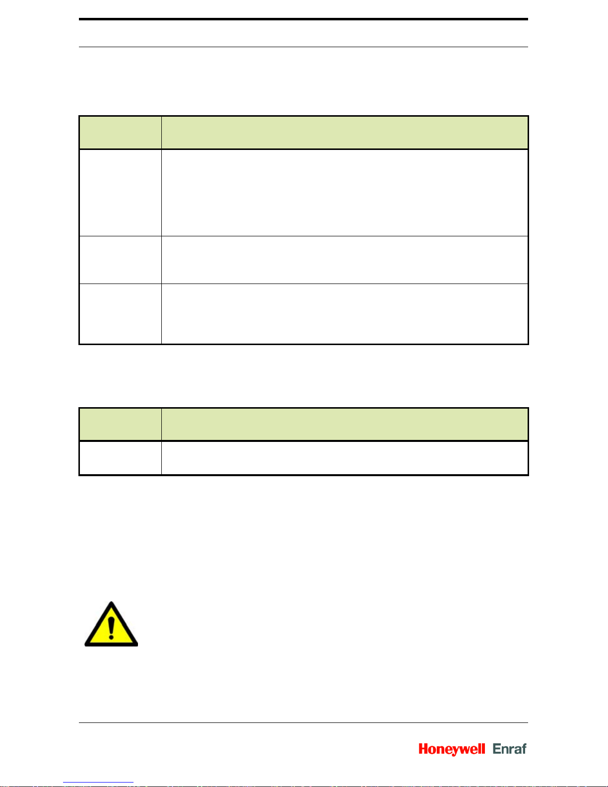
2.2 Safety Conventio n s
2.2.1 Warnings
Following warning mark is used within this document to urge
attention in order to prevent personal injuries or dangerous
situations, further described within this document.
2.2.2 Cautions
Following caution mark is used within this document to urge
attention in order to prev ent damages to t he equipment furt her
described within this document.
Symbol Description Remark
General warning Will always be explained by text.
Symbol Description Remark
General caution sign Will always be explained by text.
Page 10

Safety SmartRadar FlexLine
Installation Guide Part No.: 4417.760_Rev06
4
2.3 Safety Instruct io ns
2.3.1 Safety Instructions
See the safety instructions shipped with the device for
installation, commissioning, operation, and maintenance.
2.3.2 EC Declaration of Conformity (for EU)
See the EC declaration of conformity shipped with the device.
2.3.3 Control Drawings for FM & CSA
See the control drawings shipped with the device.
2.3.4 Wireless
Make sure the wireless FlexLine complies with local radio
regulations (FCC, ETSI, etc.).
2.3.5 Users
The mechanical and electrical installation must be carried out
only by trained personnel with knowledge of the requirement s for
installation of explosion-proof equi pm e nt in haza rd o us ar ea s.
The entire installation procedure must be carried out in
accordance with national, local, and company regulations.
The entire electrical installation shall be carried out in
accordance with the national requirements for electrical
equipment to be installed in hazardous areas.
2.3.6 Additional Information
If you require additional information, contact Honeywell Enraf or
its representative .
NOTE:
See EN IEC 60079-14 or NEC (NFPA70).
Page 11
Safety SmartRadar FlexLine
Part No.: 4417.760_Rev06 Installation Guide
5
2.3.7 Environmental Conditions
Observe the environmental conditions for the temperature and
the pressure. See Chapter 5 - Technical Data.
2.4 Liability
The information in this installation guide is the copyright property
of Honeywell Enraf, The Netherlands.
Honeywell Enraf disclaims any responsibility for personal injury
or damage to equipment caused by:
Deviation from any of the prescribed procedures.
Execution of activities that are not prescribed.
Neglect of the safety regulations for handling tools and use o f
electricity.
The contents, descriptions and specifications in this Service
Manual are subject to change without notice. Honeywell Enraf
accepts no responsibility for any errors that may appear in this
Installation Guide.
WARNING!
Only certified technicians are authorized to make
changes on the SmartRadar configuration. All
modifications must be in accordance to the guidelines as
set forth by Honeywell Enraf. Modifications not
authorized by Honeywell Enraf will invalidate the
approval certificates.
Page 12

Safety SmartRadar FlexLine
Installation Guide Part No.: 4417.760_Rev06
6
2.5 Labels
FIG. 2-1 Identification label (e xample)
Page 13

Safety SmartRadar FlexLine
Part No.: 4417.760_Rev06 Installation Guide
7
2.6 Personal Safety
2.7 Warnings and Cautions
2.7.1 General
WARNING!
In hazardous areas it is compulsory to use personal
protection and safety gear. This can be:
• safety helmet
• fire-resistive overall
• safety shoes
• safety glasses
• working gloves
•LEL-meter
Pay attention to the kind of product in the tank. If there is
any danger for your health, wear a gas mask and take all
necessary precautions.
WARNING!
Take app ropriate precautions when chemical or toxic
product vapours are present (compressed air, chemical
protection suit, detection equipment).
NOTE:
The emitted microwave energy is far below the accepted
limits for exposure to the human body. The antenna
generates a maximum radiation of 0.1 mW/cm2.
WARNING!
Make sure all power to the device is switched OFF
before you open the covers of the device. Failure to do
so may cause danger to persons or damage the
equipment. All covers of the device must be closed
before switching the power on again.
Page 14
Safety SmartRadar FlexLine
Installation Guide Part No.: 4417.760_Rev06
8
2.7.2 Tools
2.7.3 Working Environment
2.7.3.1 Hazardous Zone
2.7.3.2 Safe Zone
WARNING!
Treat the flange surface of the cover and the housing
with care. Keep the flange surface free of dirt.
The O-ring must be present and undamaged.
WARNING!
Use non-sparking tools and explosion-proof testers. Use
suitable explosion-proof tools (e.g. testing devices)!
WARNING!
POTENTIAL ELECTROSTATIC CHARGING HAZARD
• Avoid generation of static electricity.
• In case a OneWireless SmartRadar FlexLine is
installed, do NOT wipe the surface of the antenna w ith
dry cloth, and do NOT clean its surface with a solvent.
If electrostatically charged, discharge of the antenna
surface to a person or a tool could ignite a surrounding
hazardous atmosphere.
WARNING!
Make sure that no explosive gas mixtures build up in the
working area.
Page 15
Safety SmartRadar FlexLine
Part No.: 4417.760_Rev06 Installation Guide
9
2.7.4 Required Skills
2.8 Electrical
2.8.1 IEC Safety Standards
The entire electrical installation must be in accordance with
the international standard EN IEC 60079-14 for electrical
equipment in hazardous areas or the NEC (NFPA70)
requirements.
The stopping plugs, cable glands, and reducers must be
installed in accordance with appropriate IP requirements.
Use explosion proof (Ex-d) compound barrier glands (due >2
litres IIB) in case of use without SmartConn (Ex-e junction
box).
Use increased safe (Ex-e) cable glands in case a SmartConn
box is used.
Improper installation of cable glands, conduits or stopping
plugs will invalidate the Ex approval of this device.
2.8.2 Grounding
WARNING!
The technician must have technical skills to be able to
safely install the equipment. The technician also must be
trained to work in accordance with the national
requirements for electrical equipment in hazardous
areas.
WARNING!
Make sure the housing of the device is properly
connected to the ground reference! Make sure the
electrical resistance of the ground connection is below
the maximum prescribed by local requirements!
Page 16
Safety SmartRadar FlexLine
Installation Guide Part No.: 4417.760_Rev06
10
2.9 Accordance to Regulations
2.9.1 Device without SmartConn
2.9.2 Device with SmartConn
2.10 Compliance to FCC, R&TTE, IC
This device complies with EN 302372 of the R&TTE Directive,
Part 15 of the FCC Rules, and RSS-Gen of IC. The device does
not cause harmful interference and accepts any interference
received.
Protection
type
Certificate numbers
A TEX / IEC Ex
/ CSA
• SmartRadar FlexLine: KEMA 07ATEX0010X and IECEX KEM 07.0003 X
• SmartView: KEMA 07ATEX0011X and IECEX KEM 07.0004 X
• SmartConn: KEMA 07ATEX0093 and IECEX KEM 07.0031
• Without SmartView: Ex d [ia] T6 Ta: -40 °C - +65 °C
• With SmartView: Ex d [ia] ia T4 Ta: -25 °C - +65 °C
FM • Without SmartView:
Class Ι DIV Ι group C,D T6 NEMA 4X Ta: -40 °C - +65 °C
• With SmartView: Class Ι DIV Ι group C,D T4 NEMA 4X Ta: -25 °C - +65 °C
CSA • Without SmartView:
Class Ι DIV Ι group C,D T6 NEMA 4X Ta: -40 °C - +65 °C.
• With SmartView:
Class Ι DIV Ι group C,D T4 NEMA 4X Ta: -25 °C - +65 °C.
Protection
type
Certificate numbers
A TEX / IEC Ex
/ CSA
• Without SmartView: Ex de [ia] T6 Ta: -40 °C - +65 °C
• With SmartView: Ex de [ia] ia T4 Ta: -25 °C - +65 °C
WARNING!
Changes or modifications made to this equipment not
approved by Honeywell Enraf invalidate the R&TTE/
FCC/IC authorization to operate this equipment.
Page 17

Safety SmartRadar FlexLine
Part No.: 4417.760_Rev06 Installation Guide
11
2.10.1 EN 302372-1, ANNEX B
The following installation requirements shall be fulfilled:
1 SmartRadar FlexLine instruments are required to be installed at
a permanent fixed position at a closed (not open) metallic tank or
reinforced concrete tank, or similar enclosure structure made of
comparable attenuating materia l .
2 Flanges and attachments of the radar equipment shall provide
the necessary microwave sealing by design.
CAUTION!
This equipment has been tested. It complies with a Field
disturbance sensor device, pursuant to Part 15 of the
FCC Rules and FCC-Gen for IC. Operation is subject to
the following two conditions: (1) this device may not
cause interference, and (2) this device must accept any
interference, including interference that may cause
undesired operation of the device. These limits are
designed to provide reasonable protection against
harmful interference in a residential installation. This
device generates, uses and radiates radio frequency
energy. If this device is not installed and used in
accordance with the instructions, it can cause harmful
interference to radio communications. However, there is
no guarantee that interference will not occur in a
particular installation.
NOTE:
This device is certified to measure liquid levels in metal,
concrete or similar materials, enclosed tanks.
NOTE:
The radiated output power of the device is far below the
exposure limits. Nevertheless, use the device in such a
manner that the potential for human contact during
normal operation is minimal.
Page 18

Safety SmartRadar FlexLine
Installation Guide Part No.: 4417.760_Rev06
12
3 Sight glasses shall be coated with a microwave proof coating
when necessary (i.e. electrically conductive coating).
4 Manholes or connection flanges at the tank shall be closed to
ensure a low-level leakage of the signal into the air outside the
tank.
5 Whenever possible, mounting of the radar equip ment shall be on
top of the tank structure with the orientation of the antenna to
pointing in a downward direction.
6 Installation and maintenance of the radar equipment shall be
performed by professionally trained individuals only.
Page 19

Product Description SmartRadar FlexLine
Part No.: 4417.760_Rev06 Installation Guide
13
3 PRODUCT DESCRIPTION
3.1 SmartRadar System Components
FIG. 3-1 System components
The device has following system components ( see figure above):
Description
A SmartRadar FlexLine with separator coupling to radar antenna
B SmartView (optional)
C SmartConn (optional)
D Antenna connection (see antenna installation guide)
A
B
D
C
Page 20

Product Description SmartRadar FlexLine
Installation Guide Part No.: 4417.760_Rev06
14
3.2 SmartRadar FlexLine
3.2.1 Function
The SmartRadar Flexline is the core component. It provides the
level measurement, integrates optional sensor data and
communicates via the fieldbus to the host computer system.
3.2.2 Components
FIG. 3-2 General view and components of the FlexConn box (FCB)
Description (see FIG. 3-2)
A Top cover
B Display cover
C FlexConn box and FlexConn cover flange
D FlexConn cover
E Bolts with reduced shank (turn into thread when closing the cover)
F Cable entry
G Connection terminals with identification labels
A
C
E
D
F
G
H
B
J
I
Page 21

Product Description SmartRadar FlexLine
Part No.: 4417.760_Rev06 Installation Guide
15
3.3 SmartView
3.3.1 Function
The SmartView display can be part of the device. You can install
it as stand alone version as well. In this case it is placed in a
larger housing. Refer to the display installation guide.
3.4 SmartConn
3.4.1 Function
SmartConn is an optional Ex-e junction box and is only certified
for ATEX, IEC Ex and CSA. It simplifies the external connection
of the device and provides additional cable entries.
3.4.2 Components
FIG. 3-3 Optional Ex-e junction box components
H Separator coupling (connection between antenna and SmartRadar Flex-
Line)
I FlexConn box
J Inner cover (do not open, do not touch), tampering label
Description (see FIG. 3-2)
A
E
B
C
D
Page 22

Product Description SmartRadar FlexLine
Installation Guide Part No.: 4417.760_Rev06
16
3.5 Configurations
The device has several possible configurations. They can differ
in:
Measurement accuracy
Allowed process temperature ranges
Chemical compatibility
Allowed tank pressure
Weights and Measurements (W&M) approval
Explosion safety approvals
Optional features like SmartView (Display) and SmartConn
(junction box)
Allowed process temperature (Gas temperature)
Description
AEnclosure
B Cover
C Cable entry M20 (4x)(optional = 6x)
D Connection to FlexConn box
E Terminals for intrinsic safe and non-intrinsic safe connections
Page 23

Installation SmartRadar FlexLine
Part No.: 4417.760_Rev06 Installation Guide
17
4 INSTALLATION
4.1 Safety
4.1.1 General
WARNING!
Make sure the power to the device is switched OFF,
before you open the cover of the device.
CAUTION!
Do not make any additional holes in the housing. Do not
incorporate rotating machines or other devices, which
create turbulence inside the FlexConn box.
WARNING!
Always clean the FlexConn box flange, when you open
or before you close the housing.
WARNING!
Make sure that no explosive gas mixtures build up in the
working area.
NOTE:
Make sure the wireless FlexLine complies with the local
radio regulations (FCC, ETSI, etc.).
Page 24

Installation SmartRadar FlexLine
Installation Guide Part No.: 4417.760_Rev06
18
4.1.2 Hazardous Zone
4.2 Receipt
Open the box
Make sure the following items are in the box:
• The device
• The communication antenna (OneWireless option only)
• Safety instruction
• Declaration of conformity
• Installation guide
Inspect the package upon arrival. Make sure the items are
not damaged. Contact your local representative or Honeywell
Enraf in the event of damage.
WARNING!
POTENTIAL ELECTROSTATIC CHARGING HAZARD
• Avoid generation of static electricity.
• In case a OneWireless SmartRadar FlexLine is
installed, do NOT wipe the surface of the antenna w ith
dry cloth, and do NOT clean its surface with a solvent.
If electrostatically charged, discharge of the antenna
surface to a person or a tool could ignite a surrounding
hazardous atmosphere.
NOTE:
Do not throw away the packaging. The packaging is
necessary for further transport on site. The packaging is
necessary if the device is returned for service or
warranty.
Page 25

Installation SmartRadar FlexLine
Part No.: 4417.760_Rev06 Installation Guide
19
4.3 Storage
4.3.1 Storage of Uninstalled Devices
Keep the device in its original packing during storage. Keep the
device indoors during storage.
4.3.2 Storage of Installed Devices
If you do not use an installed device for a longer period, we
recommend not to disconnect the mains connection line. If this is
not possible, put some moisture-absorbing material (e.g. silica
gel) into the electronic compartment, and store the device in a
closed plastic bag.
4.4 Before Installation
Make sure following conditions are met:
The antenna- and tank separator are already installed on the
tank (see SmartRadar Antennas installation guide).
The top cover of the device can open without obstruction.
For required distances for installation, see FIG. 4-1.
The wireless FlexLine complies with local radio regulations.
Ambient conditions
Temperature -50 to +85 °C (SmartView -30 to +85 °C)
Humidity 20 to 90%
Page 26

Installation SmartRadar FlexLine
Installation Guide Part No.: 4417.760_Rev06
20
FIG. 4-1 Distances to installed device (see table below)
Device weight = 16.3 kg (36 lbs)
4.5 Installation Overview
Installation of the SmartRadar requires the following steps:
1 Mechanical installation of the device on the tank separator.
2 Preparations for connection
3 Installing the compound glands and conduits
4 Electrical connection
5 Finishing installation
These steps are further explained in the following sections.
mm inches
A 550 21.7
B 260 10.2
C 430 16.9
D300 11.8
C
B
D
A
Page 27

Installation SmartRadar FlexLine
Part No.: 4417.760_Rev06 Installation Guide
21
4.6 Mechanical Installation
4.6.1 Connect SmartRadar to Tank Separator
FIG. 4-2 Separator coupling (A) and tank separator (C)
Place device separator coupling (A) on tank separator (C).
Make sure the pin of the separator coupling fits into the corresponding opening of the tank separator.
Turn ring (B) clockwise to fasten the device. Fasten ring hand
tight.
A
B
C
Page 28

Installation SmartRadar FlexLine
Installation Guide Part No.: 4417.760_Rev06
22
4.6.2 Mount Communication Antenna (OneWireless option only)
In case of a OneWireless SmartRadar (option ), a communica tion
antenne is delivered. Mount the communication antenna by
screwing it clockwise upon the lightning arrestor (see picture
below).
NOTE:
The lightning arrestor (see figure above) protects the
inside electronics from lightning damage. Although it will
protect against multiple discharges, it can be replaced as
a preventive maintenance action. Preventive
maintenance interval depends on location, position of the
equipment, grounding, and other protection measures
installed.
2
1
communication antenna
lightning arrestor
Page 29

Installation SmartRadar FlexLine
Part No.: 4417.760_Rev06 Installation Guide
23
4.7 Preparations for Installation with SmartConn
4.7.1 Open Cover of SmartConn
FIG. 4-3 SmartConn box
Loosen the 4 bolts (A) of the cover. Use an Allen key (4 mm).
Remove cover.
A
Page 30

Installation SmartRadar FlexLine
Installation Guide Part No.: 4417.760_Rev06
24
4.8 Preparations for Installation without SmartConn
4.8.1 Remove Top Cover
FIG. 4-4 Removing the top cover
Open display cover (A)
Move up top cover (B) at the front
Remove top cover
B
A
Page 31

Installation SmartRadar FlexLine
Part No.: 4417.760_Rev06 Installation Guide
25
4.8.2 Open the Cover
FIG. 4-5 Opening the cover of the device
Loosen the 16 bolts of the cover. Use an Allen key (8 mm).
Open cover
CAUTION!
Make sure the 4 bolts (A) at the side of the hinge are
entirely screwed into the cover and do not protrude
beyond the flange of the cover. Otherwise the flange of
the housing can be damaged when closing the cover,
and this will invalidate the Ex certificate!
A
A
Page 32

Installation SmartRadar FlexLine
Installation Guide Part No.: 4417.760_Rev06
26
4.9 Installing the Cable Glands and Stopping Plugs with
SmartConn
4.9.1 Cable Glands
Use increased safe (Ex-e) M20 cable glands with an appro-
priate IP value.
See the type plate on the device.
4.9.2 Unused Cable Inlets
Seal unused cable inlets with approved threaded stopping
plugs.
4.10 Installing the Compound Glands, Conduits, and Stopping
Plugs without SmartConn
Depending on local regulations, this device can be cabled by
using compound glands, direct entry, or conduits.
CAUTION!
Only use Ex-e or flameproof certified materials of an
appropriate IP value.
CAUTION!
Improper installation of cable glands or stopping plugs
will invalidate the Ex approval of the SmartRadar.
NOTE:
Install the cable glands according to the instructions
provided by the manufacturer.
CAUTION!
Only use Ex-d certified materials of an appropriate IP
value.
Page 33

Installation SmartRadar FlexLine
Part No.: 4417.760_Rev06 Installation Guide
27
4.10.1 Compound Glands
Use explosion proof (Ex-d) compound glands with an appro-
priate IP value.
4.10.2 Conduits
Use explosion proof (Ex-d) conduits with an appropriate IP
value. See the type plate on the device.
CAUTION!
Improper installation of cable glands, conduits, or
stopping plugs will invalidate the Ex approval of the
SmartRadar.
NOTE:
Only for use in ATEX and IEC Ex approved installations.
NOTE:
Install the compound glands according to the instructions
provided by the manufacturer.
WARNING!
If the SmartRadar is installed in a hazardous area:
• Metal conduits must be used, size 3/4”.
• Stopper boxes must be installed within 45 cm (18”) of
the device to seal the cabling in the conduit.
NOTE:
Install the conduits according to the instructions provided
by the manufacturer.
Page 34

Installation SmartRadar FlexLine
Installation Guide Part No.: 4417.760_Rev06
28
4.10.3 Unused Cable Inlets
Seal unused cable inlets with approved 3/4” threaded
stopping plugs.
4.11 Electrical Connection
CAUTION!
Cables must always comply with the defined cable
specifications.
CAUTION!
• Minimum incoming wire cross section should be at least
0.2 mm2 and may consist of a single-, fine- or multiwire. With the use of wire with a cross section between
≥0.2 mm
2
and <0.5 mm2, the maximum current I [A]
should be reduced to a maximum of I = 0.55 A.
• With a minimum wire cross section of ≥0.5 mm2 the
maximum current I should not be higher than 3 A and
may consist of a single-, fine- or multi-wire.
NOTE:
The field cabling entering the SmartConn box must be as
short as possible.
NOTE:
Depending on the ambient temperature classification the
cables must be suitable for Ta > 70°C.
Page 35

Installation SmartRadar FlexLine
Part No.: 4417.760_Rev06 Installation Guide
29
4.11.1 Grounding
The SmartRadar housing must be properly grounded to the
ground reference (generally the tank), according to local
regulations. This is a safety grounding requirement.
4.11.2 Introduction
WARNING!
When measuring the ground resistance, use a suitable
instrument that is approved for use in hazardous areas.
WARNING!
Safety depends on proper grounding. Check the
resistance of the ground connection directly after
installation. The measured ground resistance must be
below the maximum prescribed by local and/or national
grounding requirements.
WARNING!
The intrinsically safe options have been certified for use
in hazardous areas. Make sure that the certificate of
approval is available on site and act in accordance with
the instructions as given in the certificate .
WARNING!
Intrinsically safe wiring must be separated from all other
wiring. The cable lay-out must be in accordance with
local and/or national regulations.
NOTE:
Connect the armouring of the cable externally in the
cable gland at both ends of the cable.
Page 36

Installation SmartRadar FlexLine
Installation Guide Part No.: 4417.760_Rev06
30
4.11.2.1 Location
The terminal compartment is located at the rear, inside of the
device (see FIG. 4-7). If there is a SmartConn present, you use
the terminals of the Smar tConn (see FIG. 4-6). These terminals
are numbered identical to the terminal compartment in the
device.
4.11.2.2 Connections
The intrinsically safe cabling must enter at the gland (C) only.
This entry is marked "Ex-i". See FIG. 4-6. Blue marked cables
are recommended for the intrinsically safe options.
FIG. 4-6 Ex-i entry with SmartConn
Description
A Blue terminals, for intrinsically safe connections
B Grey terminals, for non-intrinsically safe connections
C Glands for intrinsically safe cabling only
C
A
B
Page 37

Installation SmartRadar FlexLine
Part No.: 4417.760_Rev06 Installation Guide
31
4.11.2.3 Terminals
FIG. 4-7 Terminal layout without SmartConn
The terminal compartment is divided into two zones:
Blue terminals (A), for intrinsically safe connections, such as
HART, VITO and SmartView.
Grey terminals (B), for non-intrinsically safe connections.
The indices of the terminals are variable. For each option there
are indices on the terminal row. They are specified in a label
attached in front of the terminal row, as is schematically indicated
in figure 4.8.
The terminals for the power supply are standard.
Some terminal contacts can be double labelled. In this case the
white text on black label is the first option for connection. The
black text on white label is the second option for connection.
NOTE:
The SmartConn box is also available with 6 cable
entries.
B
A
Page 38

Installation SmartRadar FlexLine
Installation Guide Part No.: 4417.760_Rev06
32
FIG. 4-8 Terminal labelling
4.11.2.4 General Procedure
Connect the wiring to the terminals with the numbers as
shown in the tables in the following sections.
4.11.3 Non-intrinsically Safe Connections
The non-intrinsically safe connections are connected to the grey
wiring terminal.
If local and or nation al re gu la tio ns a llo w, the power supply, Enraf
fieldbus, and hardware relay outputs may be combined into one,
unshielded, cable.
A separate cable may also be used for each.
4.11.3.1 Power Supply
Connect th e power supply to either:
• DC: 24 - 65 Volt
• AC: 65 - 240 Volt
18
17
16
15
14
Page 39

Installation SmartRadar FlexLine
Part No.: 4417.760_Rev06 Installation Guide
33
4.11.3.2 Enraf Fieldbus (BiPhase Mark)
4.11.3.2.1 Topology
A maximum of 10 devices can be connected to the Enraf field
bus line.
NOTE:
The DC polarity is not critical.
NOTE:
Install an explosion proof mains switch in the mains
cable to the SmartRadar.
Cable specifications
Type Suitable for the SmartRadar power rating, and approved
for use in hazardous areas
Label Parameters
00. Vin-a/L 24-65 Vdc -15/+10%
65-240 Vac -15/+10%
50/60 Hz ± 10%
Automatic selection
01. Vin-b/N
Cable specifications
Type Twisted pair; R
max
= 200 Ohm /line, C
max
= 1 μF.
Maximum length 10 km
Label Parameters
06. TL1 1200/2400/4800 bps
Selection by software
07. TL2
Page 40

Installation SmartRadar FlexLine
Installation Guide Part No.: 4417.760_Rev06
34
For short distances up to 20 devices can be connected. This
number will be specific to every situation.
4.11.3.3 Host Communication EIA 485
4.11.3.3.1 Topology
Up to 31 gauges can be connected to one EIA 485 Host
communication. The gauges are connected in parallel, as
described in figure 4.9.
FIG. 4-9 EIA 485 topology
Cable specifications
Type Twisted pair, shielded
Maximum length 1200 meter
NOTE:
If necessary the ‘common’ of the EIA 485 may be
connected to the ground GND_ISO.
Label Parameters
11. 485A 1k2/2k4/4k8/9k6/19k2/38k4 bps
Selection by software
12. 485B
13. GND_ISO
EIA 485 Field bus
13. GND_ISO
12. 485B
11. 485A
13. GND_ISO
12. 485B
11. 485A
13. GND_ISO
12. 485B
11. 485A
Page 41

Installation SmartRadar FlexLine
Part No.: 4417.760_Rev06 Installation Guide
35
4.11.3.4 Host Communication EIA 232
4.11.3.4.1 Topology
EIA 232 Host communication is for point-to-point
communication. One gauge can be connected per host.
FIG. 4-10 EIA 232 topology
4.11.3.5 Hardware Relay Outputs (FII-DO)
The hardware relay outputs can be used as an alarm sig nal or to
operate a remote device.
The signals corresponding with the terminal labels are
programmed during commissioning.
Cable specifications
Type Shielded
Maximum length 15 meter
Label Parameters
08. 232RX 38k4/19k2/9k6/4k8/2k4/1k2 bps
Selection by software
09. 232TX
10. GND_ISO
Cable specifications
Type Approved for use in hazardous areas and suitable for the specified
power rating.
08. 232RX
09. 232TX
10. GND_ISO
EIA 232 Field Bus
Page 42

Installation SmartRadar FlexLine
Installation Guide Part No.: 4417.760_Rev06
36
4.11.3.5.1 FII-DO
4.11.3.5.2 FII-DO - Overfill Protection
4.11.3.6 HCI-HAO
Label Parameters
14. Ry1_a Vmax = 125 Vac, Imax = 0.5 A
Vmax = 110 Vdc, Imax = 0.3 A
Pmax = 30 W
NO/NC by factory jumper
15. Ry1_b
16. Ry2_a Vmax = 125 Vac, Imax = 0.5 A
Vmax = 110 Vdc, Imax = 0.3 A
Pmax = 30 W
NO/NC by factory jumper (default = NO)
17. Ry2_b
18. Ry3_a Vmax = 250 Vac, Imax = 3 A
Vmax = 40 Vdc, Imax = 3 A
Pmax = 750 W
NO/NC by factory jumper
19. Ry3_b
20. Ry4_a Vmax = 250 Vac, Imax = 3 A
Vmax = 40 Vdc, Imax = 3 A
Pmax = 750 W
NO/NC by factory jumper
21. Ry4_b
Label Parameters
48. Ofp_a Vmax = 250 Vac, Imax = 3 A
Vmax = 40 Vdc, Imax = 3 A
Pmax = 750 W
NO/NC by factory jumper
49. Ofp_b
Cable specifications
Type Shielded twisted pair
Maximum length 1200 meter
Label Parameters
46. 4-20 mA +
47. 4-20 mA -
Page 43

Installation SmartRadar FlexLine
Part No.: 4417.760_Rev06 Installation Guide
37
4.11.4 Intrinsically Safe Connections
The intrinsically safe connections are connected to the blue
wiring terminal.
4.11.4.1 VITO
For temperature and water bottom measurement.
4.11.4.1.1 Topology
Only one device can be connected to the VITO connection.
4.11.4.2 HART
Cable specifications
Type Twisted pair, shielded. R
max
= 25 Ω / line
Maximum length 1000 meter
Label Parameters
22. V_Loop [Ex ia] IIB
U
o
= 23.1 V
I
o
= 124 mA
P
o
= 0.6 W
C
o
= 1.0 μF
L
o
= 9 mH
23. GND_Loop
Cable specifications
Type Twisted pair, shielded. R
max
= 25 Ω / line
Maximum length 1000 meter
Label Parameters
24. V_Loop [Ex ia] IIB
U
o
= 23.1 V
I
o
= 124 mA
P
o
= 0.6 W
C
o
= 1.0 μF
L
o
= 9 mH
25. GND_Loop
Page 44

Installation SmartRadar FlexLine
Installation Guide Part No.: 4417.760_Rev06
38
4.11.4.2.1 Topology
A maximum of 5 devices can be connected to the HART
connection.
CAUTION!
Before connecting the HART devices:
Make sure the sum of the start-up currents fits the
parameters.
Page 45

Installation SmartRadar FlexLine
Part No.: 4417.760_Rev06 Installation Guide
39
4.11.4.3 FII-RTD
4.11.4.3.1 RTD, 4-Wire Connection (Board ID = 2)
4.11.4.3.2 RTD, 3-Wire Connection (Board ID = 3)
Cable specifications
Type Shielded. R
max
= 100 Ω / line
Maximum length 150 meter
Label Connections diagram Parameters
30. RTD1_S- [Ex ia] IIB/IIC
U
o
= 8.61 V
I
o
= 58 mA
P
o
= 0.13 W
C
o
= 1.0 μF
L
o
= 10.5 mH
31. RTD1_com
32. RTD1_pos
33. RTD1_S+
34. RTD2_S-
35. RTD2_com
36. RTD2_pos
37. RTD2_S+
Label Connections diagram Parameters
30. RTD1_S- [Ex ia] IIB/IIC
U
o
= 8.61 V
I
o
= 58 mA
P
o
= 0.13 W
C
o
= 1.0 μF
L
o
= 10.5 mH
31. RTD1_com
32. RTD1_pos
34. RTD2_S-
35. RTD2_com
36. RTD2_pos
RTD1
R
c1
RTD2
R
c2
RTD1
R
c1
RTD2
R
c2
Page 46

Installation SmartRadar FlexLine
Installation Guide Part No.: 4417.760_Rev06
40
4.11.4.3.3 MPT - MRT (Board ID = 4)
4.11.4.4 Stand-alone SmartView Display
The labelling on the wiring terminal in the SmartView is identical
to the labelling in the SmartRadar.
Label Connections diagram Parameters
38. S- [Ex ia] IIB/IIC
U
o
= 8.61 V
I
o
= 58 mA
P
o
= 0.13 W
C
o
= 1.0 μF
L
o
= 10.5 mH
39. com
40. R1
41. R2
42. R3
43. R4
44. R5
45. R6
Cable specifications
Type 4-wire, shielded
Maximum length 50 meter
Label Parameters
26. SGND [Ex ia] IIB
U
o
= 14.2 V
I
o
= 522 mA
P
o
= 1.7W
C
o
= 2.18 μF
L
o
= 0.25 mH
27. Vsafe_+
28. Safe_A
29. Safe_B
R
c
R1
R2
R3
R4
R5
R6
Page 47

Installation SmartRadar FlexLine
Part No.: 4417.760_Rev06 Installation Guide
41
4.12 Finishing Installation with SmartConn
Replace the cover on the SmartConn.
Tighten the 4 bolts of the cover. Use an Allen key (4 mm).
The installation is now completed.
4.13 Finishing Installation without SmartConn
4.13.1 Close the Cover of the Device
Close the cover. Make sure that the cover does not squeeze
any cables inside the housing.
CAUTION!
Make sure the separation between intrinsic and non
intrinsic cabling is sufficient and complies with any local
and/or national regulations.
WARNING!
Tighten all bolts with a torque of 30 Nm (711 ft·lbf) to
prevent danger of explosion!
CAUTION!
Always clean the flange of the housing and the cover,
before you close the cover.
WARNING!
Make sure the flange of the housing is clean and the O-
ring is not damaged before closing the cover.
Page 48

Installation SmartRadar FlexLine
Installation Guide Part No.: 4417.760_Rev06
42
Tighten the 16 bolts of the cover. Tighten the bolts crosswise.
Use an Allen key (8mm).
4.13.2 Replace the Top Cover
Open the display cover.
Place the 2 hooks at the rear of the top cover behind the axis
of the cover.
Push down the top cover carefully.
The installation is now completed.
Page 49

Technical Data SmartRadar FlexLine
Part No.: 4417.760_Rev06 Installation Guide
43
5 TECHNICAL DATA
5.1 Weight and Dimensions
FIG. 5-1 SmartRadar and SmartConn dimensions
Weight = 13.6 kg (36 lbs).
mm inches
A 300 11.82
B 330 12.99
C90 3.54
D 220 8.66
E70 2.76
F 260 10.24
B
A
D
E
C
F
Page 50

Technical Data SmartRadar FlexLine
Installation Guide Part No.: 4417.760_Rev06
44
Page 51

Page 52

Honeywell Enraf
Delftechpark 39
2628 XJ Delft
The Netherlands
Tel: +31 (0)15-2701 100
www.honeywellenraf.com
4417760 - Revision 06
July 2011
© 2011 Honeywell International Inc.
 Loading...