

Page 1
FC1-OI-EN h 2017-11-16
as of 2017-11-16
From Basic System version 03-22
Flow Computer
Device Series enCore FC
FC1, MC1
Manual
Operating Instructions
Page 2
Page 2 of 120
Operating Instructions
enCore FC
Disclaimer
The information contained in this document is the property of Honeywell. The following
information is to be used exclusively for the intended purpose. This document or its
contents may not be reproduced, published or made available to a third party in whole
or in part without the express permission of Elster GmbH.
All information and descriptions in this Operating Instructions have been compiled
after careful examination. Nevertheless, errors cannot be completely excluded.
Honeywell therefore does not guarantee the completeness or correctness of the
content. The manual cannot be understood as a guarantee of product properties. It
also describes properties that are only available as an option.
Honeywell is in no case liable to third parties for direct, special or consequential
damages. The information in this document is subject to change without notice.
With regard to extended product liability, the data and material properties listed may
only be regarded as guidelines and must always be checked and, if necessary,
corrected on a case-by-case basis. This is particularly true where safety aspects are
concerned.
Further support is available from your local office or representative. The address can
be found on the Internet or at Honeywell.
The passing on and reproduction of this manual or parts thereof is only permitted with
the written permission of Honeywell.
If the product described herein is improperly handled, repaired or modified by
unauthorized persons or if Honeywell spare parts other than original spare parts are
used, the warranty will be void.
This product may contain or be derived from third party material, including software.
Third party material may be subject to license terms, notices, restrictions and
obligations of the Licensor. The licenses, notices, restrictions and obligations, if any,
may be found in the materials accompanying the Product, in the documents or files
containing the material of third parties, in a file called third_party_licenses on the
media containing the Product, or at www.honeywell.com/ps/thirdpartylicenses.
Copyright © 2017 Elster GmbH, D-55252 Mainz-Kastel. All rights reserved.
Dortmund, October 2017
Page 3

enCore FC
Operating Instructions
Page 3 of 120
Contents
1 General Information 8
1.1 The enCore/enSuite Concept 8
1.2 Scope of Delivery 9
2 About these Instructions 11
2.1 Target Group Definition 11
2.2 The enCore FC Manual at a Glance 13
2.3 Text Labelling 15
2.3.1 Presentation of Safety and Risk Instructions 15
2.3.2 Paragraph Formats 16
2.3.3 Character Formats 17
2.3.4 Character Formats in Flow Charts 18
2.4 Limitation of Liability 19
2.5 Applicable Standards and Guidelines 20
3 Security considerations for your network 21
4 Safety 23
4.1 General Safety Instructions 23
4.2 Intended Use 25
4.3 Unacceptable use while Impaired 26
4.4 Operator Liability 26
5 Design and Function 28
5.1 Functional Description of enCore FC devices 28
5.1.1 Number of Streams and their Flow Directions 29
5.1.2 International Standards 29
5.2 Device Description 30
5.3 Operation Panel 31
5.3.1 Device Keys 32
5.3.2 Touch Screen 32
Page 4

Contents
Page 4 of 120
Operating Instructions
enCore FC
5.3.3 Operation and Navigation within the Display 33
5.3.4 Security Switch 36
5.3.5 LEDs 36
5.4 Interfaces (Rear Side of Device) 39
5.5 Available Process Boards 40
5.5.1 ExMFE5 Process Board 40
5.5.2 MFE7 Process Board 43
5.5.3 MSER4 Process Board 43
5.5.4 ESER4 Process Board 44
5.5.5 MFA8 Process Board 44
6 Assembly Instructions 45
6.1 Line Connection 45
6.2 Power Supply and Grounding 47
6.3 Installation and Conversion of Process Boards 48
6.3.1 Insert a Process Board in a Free Board Slot 49
6.4 Connection Diagrams 54
6.4.1 General Recommendations for Signal and Data Cable 55
6.4.2 Pt100 (EEx i) via ExMFE5 Board 57
6.4.3 Pt100 (EEx d) via MFE7 Board 58
6.4.4 Analog Measurement Transmitter (EEx i) via ExMFE5 Board 59
6.4.5 Analog Measurement Transmitter (EEx d) via MFE7 Board
(without barrier) 60
6.4.6 Analog Measurement Transmitter (EEx i) via MFE7 Board
(barrier in sink mode) 61
6.4.7 Analog Measurement Transmitter (EEx i) via MFE7 Board
(barrier in source mode) 62
6.4.8 HART Measurement Transmitter (EEx i) via ExMFE5 Board 63
6.4.9 HART Measurement Transmitter (EEx d) via MFE7 Board
(without barrier, internal Power Supply) 65
6.4.10 HART Measurement Transmitter (EEx d) via MFE7 Board
(without barrier, external Power Supply) 67
6.4.11 HART Measurement Transmitter (EEx i) via MFE7 Board
(barrier in sink mode) 69
Page 5

Contents
enCore FC
Operating Instructions
Page 5 of 120
6.4.12 HART Measurement Transmitter (EEx i) via MFE7 Board
(barrier in source mode) 71
6.4.13 HART Measurement Transmitter (EEx d) via MFE7 Board
(redundant, without barrier) – Burst Mode 73
6.4.14 HART Measurement Transmitter (EEx i) via MFE7 Board
(redundant, barrier in source mode) – Burst Mode 75
6.4.15 HART Measurement Transmitter (EEx d) via MFE7 Board
(Multi-Master, without barrier) – Multidrop Mode (from Basic
System 03-25) 77
6.4.16 HART Measurement Transmitter (EEx i) via MFE7 Board
(Multi-Master, barrier in source mode) – Multidrop Mode (from
Basic System 03-25) 79
6.4.17 Gas Meter (Turbine): Encoder Index, 2 LF/HF Sensors (EEx i)
via ExMFE5 Boards 81
6.4.18 Gas Meter (Turbine): Encoder Index, 2 LF/HF Sensors (EEx i)
via MFE7 Board 82
6.4.19 Gas Meter (Turbine) SMRI Bi-directional: 2 HF Sensors, Flow
Direction Detection (EEx i) via MFE7 Board 84
6.4.20 Gas Meter (Turbine) SMRI Bi-directional:
Flow Direction Detection Internal (EEx i) via MFE7 Board 85
6.4.21 Q.Sonic Ultrasound Gas Meter: Serial RS485 (EEx d) via
MFE7 Board 87
6.4.22 Q.Sonic6 Ultrasound Gas Meter: Serial RS485 (EEx d) via
MFE7 Board 88
6.4.23 FLOWSIC600 Ultrasound Gas Meter: Serial RS485 (EEx d)
via MFE7 Board 89
6.4.24 Serial Interface through COM Port (CPU or MSER4-Board) 90
6.4.25 Analog Output over MFA8 Board (0/4 ... 20 mA) 92
6.4.26 Message Output over MFA8 Board 93
6.4.27 Pulse Output over MFA8 Board 95
7 Device Configuration and Commissioning 96
7.1 Device Configuration 97
7.2 Commissioning the Measurement System 98
7.2.1 Checking Device Settings 99
7.2.2 Checking Measurement Input Values 99
Page 6
Contents
Page 6 of 120
Operating Instructions
enCore FC
7.2.3 Checking Output Signals 99
7.2.4 Checking Digital Communication (Modbus, etc.) 99
7.2.5 Checking Measurements and Calculations 99
7.2.6 End of Commissioning (from Basic System 03-24) 99
7.2.7 Sealing (if necessary) 100
8 Maintenance 101
8.1 Battery Replacement 101
8.1.1 Changing Batteries 102
8.2 Cleaning 104
8.3 Technical Assistance Center (TAC) 105
8.4 Replacement Parts and Accessories 105
8.5 Warranty Conditions 106
9 Decommissioning/Disposal 107
9.1 Storage 107
9.2 Disposal 108
10 Technical Data 109
10.1 General Information 109
10.2 Input channels 110
10.3 Outputs 111
10.4 Interfaces for Digital Communication 112
10.5 Data Protocols 112
10.5.1 Data protocols and its TCP default port (Ethernet) 113
10.6 Housing dimensions 114
10.6.1 1/3 housing width 114
10.6.2 1/2 housing width 115
11 FAQs 116
11.1 How to report a security vulnerability to Honeywell? 116
11.2 Limitations for multidrop and burst mode up to basic system version ≤
03-24 116
Page 7

Contents
enCore FC
Operating Instructions
Page 7 of 120
12 Index 118
13 Appendix 120
Page 8
Operating Instructions
1 General Information
1.1 The enCore/enSuite Concept
enCore is the name of an Elster product platform for advanced measure-
ment devices. All enCore devices are based on the same hardware
components and software concepts. Both the hardware and software of
enCore devices have a modular design; the configuration of the process
board equipment and the arrangement of software components are variable.
On one hand, the software components consist of basic functionalities,
which are provided by the Basic System with its System Function Blocks
(abbreviated as: SFBs), and on the other hand consist of application-related
functionalities, which come with different Application Function Blocks
(abbreviated as: AFB). Owing to this modular design principle, each device
can be optimally adapted to individual requirements.
enSuite is the name of the PC software supporting all enCore devices along
with a number of other Elster devices. The enSuite software provides tools
for configuration, parameterization, diagnosis, software downloads and other
services.
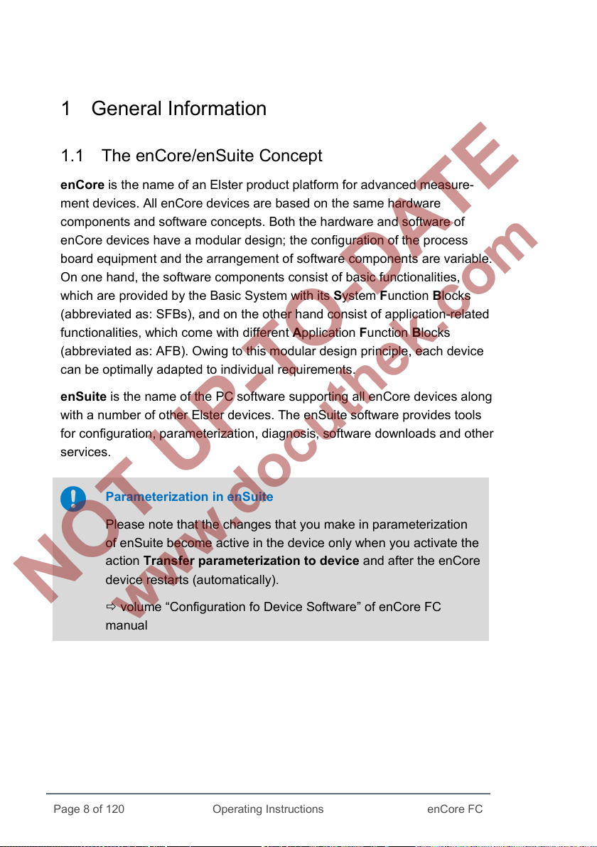
Parameterization in enSuite
Please note that the changes that you make in parameterization
of enSuite become active in the device only when you activate the
action Transfer parameterization to device and after the enCore
device restarts (automatically).
volume “Configuration fo Device Software” of enCore FC
manual
Page 8 of 120
enCore FC
Page 9
1 General Information
enCore FC
Operating Instructions
Page 9 of 120
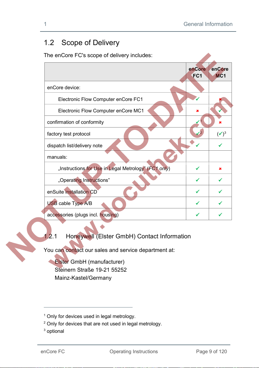
1.2 Scope of Delivery
The enCore FC's scope of delivery includes:
enCore device:
Electronic Flow Computer enCore FC1
Electronic Flow Computer enCore MC1
confirmation of conformity
factory test protocol
dispatch list/delivery note
manuals:
„Instructions for Use in Legal Metrology” (FC1 only)
„Operating Instructions”
enSuite installation CD
USB cable Type A/B
accessories (plugs incl. housing)
1.2.1 Honeywell (Elster GmbH) Contact Information
enCore
FC1
1
2
enCore
MC1
()3
You can contact our sales and service department at:
Elster GmbH (manufacturer)
Steinern Straße 19-21 55252
Mainz-Kastel/Germany
1
Only for devices used in legal metrology.
2
Only for devices that are not used in legal metrology.
3
optional
Page 10

General Information 1
Page 10 of 120
Operating Instructions
enCore FC
Phone: +49 6134 605-0
Email: info@elster.com
Website: www.elster-instromet.com
You can reach our Technical Assistance Center (TAC) at:
Phone: +49 231 937110-88
Email: ElsterSupport@Honeywell.com
Website: www.elster-instromet.com
Page 11
enCore FC
Operating Instructions
Page 11 of 120
2 About these Instructions
The present documentation are the Operating Instructions of the overall
documentation, and describe the assembly, installation, commissioning and
maintenance of the flow computer enCore FC series (called enCore FC
below).
These instructions make it possible to work with the enCore FC in a safe and
efficient manner.
Compliance with all the safety and handling instructions specified in these
Operating Instructions is a prerequisite to working with the enCore FC in a
safe manner and using it properly, and for obtaining accurate measurement
and calculation results.
In addition, compliance is also necessary with the guidelines, standards,
local accident prevention regulations and general safety regulations that
apply for the enCore FC's area of application.
The illustrations in this manual serve to depict the facts that are being
explained, and therefore may differ from the actual design of the enCore FC
depending on the configuration of the device and enSuite.
The data and material properties that are presented below are
guidelines. They must be reviewed for each individual case and
corrected if required.
2.1 Target Group Definition
The present documentation is directed to qualified electricians in the fields of
switch cabinet construction and maintenance, as well as qualified personnel
with specialized knowledge in device assembly and commissioning.
The qualifications for different areas of activity are listed below:
• trained individual
A person, who has been instructed by the plant operator in an
Page 12

About these Instructions 2
Page 12 of 120
Operating Instructions
enCore FC
informational session on the tasks assigned to him or her, and on
possible hazards in case of improper behavior.
• specialist personnel
A person who has the ability, because of his or her technical
training, knowledge and experience, as well as his or her
knowledge of the relevant regulations, to carry out the work
assigned to him or her at the enCore FC, and to recognize and
avoid possible hazards independently.
• gas specialist
A person who has the ability, because of his or her technical
training, knowledge and experience, as well as his or her know-
ledge of the relevant standards and regulations, to carry out work in
gas systems, and to recognize possible hazards independently. A
gas specialist receives training for the specific location in which he
or she works, and is acquainted with the relevant standards and
regulations.
• authorized metrology expert
A person who has the ability and is authorized, because of his or
her technical training, knowledge and experience, to carry out
legally relevant tasks in gas systems within the scope of legal
metrology. An authorized metrology expert is acquainted with the
relevant standards and legal regulations that apply in specific
countries. In the European Union the legally relevant tasks are
executed by designated notified bodies.
• qualified electrician
A person who has the ability, because of his or her technical
training, knowledge and experience, as well as his or her know-
ledge of the relevant standards and regulations, to carry out work in
electrical systems, and to recognize and avoid possible hazards
independently. A qualified electrician receives training for the
specific location in which he or she works, and is acquainted with
the relevant standards and regulations.
Page 13
2 About these Instructions
enCore FC
Operating Instructions
Page 13 of 120
2.2 The enCore FC Manual at a Glance
The manual for the enCore FC device series is modular:
For all device types that can be used in legal metrology, there is a volume
that specifically describes the legally relevant functions and characteristics.
All other volumes of the manual apply to all devices of the enCore FC series,
i.e. they are independent of the device type.
The manual consists of the following volumes:
• “Instructions for Use in Legal Metrology”, enCore FC1 only
This volume focuses on the legally relevant properties and
functions of the FC1 flow computer.
• “Operating Instructions”
This volume describes the assembly, installation, commissioning
and maintenance of all enCore FC devices.
• “Configuration of Device Software”
This volume describes parameterizing devices of the enCore series
with the software system enSuite, the software download and
further services.
• “Basic System with SFBs”
This volume describes the basic system, which provides all basic
functions of the device software. The basic system e.g. manages
the system resources, the I/O boards or the connection to other
devices via digital protocols.
• Functionality of individual Application Function Blocks
Each volume describes the parameterization, function and
operation of each AFB. These volumes always describe the full
range of functions of the respective AFBs.
Page 14

About these Instructions 2
Page 14 of 120
Operating Instructions
enCore FC
Delivery form of the individual volumes
Die Anleitung zur „Verwendung im gesetzlichen Messwesen“ und
die „Betriebsanleitung“ sind Produktbestandteile und werden in
gedruckter Form mit dem Gerät ausgeliefert.
Bewahren Sie diese Dokumente in unmittelbarer Nähe des
enCore FC zur Verwendung für das Fachpersonal der benannten
Stellen sowie für das Installations-, Bedienungs-, Wartungs- und
Reinigungspersonal jederzeit zugänglich auf.
Alle weiteren Bände des enCore FC-Handbuchs können Sie im
PDF-Format aus unserer Docuthek (www.docuthek.com)
herunterladen. Zusätzlich stehen hier die Anleitung zur „Operating
Instructions“ sowie die „Betriebsanleitung“ in digitaler Form zur
Verfügung.
Die Dokumente in der Docuthek werden regelmäßig aktualisiert.
Manuals as product components
The volume “Use in Legal Metrology” and this “Operating
Instructions” are product components and delivered in printed
form with the device. Therefore, these must always be kept in the
immediate vicinity of the enCore FC and easily accessible to the
installation, operational, maintenance and cleaning personnel.
All other volumes of the enCore FC manual can be downloaded
from our Docuthek (www.docuthek.com) in PDF format. In
addition, the instructions for "Use in Legal Metrology" as well as
the "Operating instructions" are available in digital form.
The documents in the Docuthek are regularly updated.
Page 15

2 About these Instructions
enCore FC
Operating Instructions
Page 15 of 120
2.3 Text Labelling
Texts containing different contents are labelled differently. With the help of
following characteristics, you can identify which content of the text is pro-
vided to you:
2.3.1 Presentation of Safety and Risk Instructions
Hazard Warnings
Hazard warnings indicate hazardous situations which may result in material
damage and bodily harm or even death if disregarded.
Hazard warnings are described below:
DANGER WORD!
Type of danger
Consequences in case of non-compliance
Avoiding danger
The danger word signals the hazard level:
• DANGER!
… indicates an imminently hazardous situation that leads to death
or severe injuries.
• WARNING!
… indicates a possibly hazardous situation that may lead to death
or severe injury.
• CAUTION!
… indicates a possibly hazardous situation that may lead to slight
or minor injuries.
• ATTENTION!
… indicates a possibly hazardous situation that may lead to
material damage.
Page 16

About these Instructions 2
Page 16 of 120
Operating Instructions
enCore FC
Safety Instructions
Safety instructions include notes and information which if disregarded may
lead to functions not working correctly or not working at all.
Safety instructions are described below:
Safety instruction (optional)
Safety instruction text
Tips and recommendations
Tips include notes and information that make it easier for the user to operate
the enCore FC.
Tips are described below:
Heading (optional)
Hint text
2.3.2 Paragraph Formats
► This triangle prompts you for an action.
This character will show you the immediate result of your action.
For the enCore FC symbol, the result of your operation is shown in
Example
Multi-row examples are marked by two continuous blue lines and the
keyword “Example”.
running operation of the device after you have transferred an enSuite
parameterization to the device and the device is restarted with this para-
meterization.
Page 17

2 About these Instructions
enCore FC
Operating Instructions
Page 17 of 120
2.3.3 Character Formats
Example Use
Time Service
chapter 2.3.3 Character
Formats (p. 17)
Tab Parameters
[OK]
[F1]
<Modbus AFB >
[Group 1.]Modbus
Names of the individual SFB and AFB soft-
ware elements of the enCore FC.
References to additional information are
marked with an arrow. If the arrow refers to
information within document, these referen-
ces are formated as hyperlinks in blue font.
You directly go to corresponding text pas-
sage by clicking the blue text.
Marking of graphic screen elements or
messages which you find again on the
screen. These include, for example, menu
items, marking of tabs and parameters.
Marking of buttons and keys are additionally
framed with square brackets.
Place holders are specified in angle-
brackets and represent the corresponding,
current value of your system – as in the ex-
ample the name of the Modbus AFB.
Optional information is specified in square
brackets. In the example, Group 1 is shown
only when a group has been created in your
device.
admin1
www.docuthek.com
Texts which you enter in enSuite in the
corresponding field.
links (Hyperlink)
Page 18
About these Instructions 2
Page 18 of 120
Operating Instructions
enCore FC
generated counters
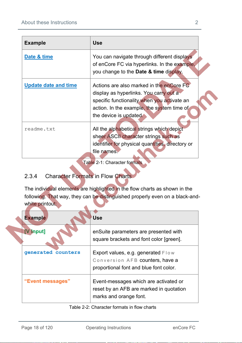
Example Use
Date & time
You can navigate through different displays
of enCore FC via hyperlinks. In the example,
you change to the Date & time display.
Update date and time
Actions are also marked in the enCore FC
display as hyperlinks. You carry out a
specific functionality when you activate an
action. In the example, the system time of
the device is updated.
readme.txt
All the alphabetical strings which depict
sheer ASCII character strings such as
identifier for physical quantities, directory or
file names.
Table 2-1: Character formats
2.3.4 Character Formats in Flow Charts
The individual elements are highlighted in the flow charts as shown in the
following. That way, they can be distinguished properly even on a black-and-
white printout:
Example Use
[V Input]
“Event messages”
enSuite parameters are presented with
square brackets and font color [green].
Export values, e.g. generated Flow
Conversion AFB
counters, have a
proportional font and blue font color.
Event-messages which are activated or
reset by an AFB are marked in quotation
marks and orange font.
Table 2-2: Character formats in flow charts
Page 19
2 About these Instructions
enCore FC
Operating Instructions
Page 19 of 120
2.4 Limitation of Liability
All specifications and instructions in these Operating Instructions were
compiled after taking into consideration the applicable standards and
regulations, the current state of the art and the knowledge and experience
we gained over the years.
The manufacturer assumes no liability for loss due to:
• non-compliance with these Operating Instructions
• unintended use
• use of the device by non-instructed personnel
• unauthorized device modifications
• technical changes
• use of non-authorized replacement parts
The actual scope of delivery may differ from the explanations and de-
scriptions included here in case of special device designs, the use of
additional order options or because of the latest technical changes.
The obligations arranged in the delivery contract apply, as do the General
Terms and Conditions, manufacturer delivery conditions and current legal
regulations that apply at the time the contract was concluded.
Read through these Operating Instructions carefully before
beginning any work to and with the enCore FC, especially before
commissioning the device!
The manufacturer assumes no liability for loss and malfunctions
that result from non-compliance with these instructions.
We reserve the right to make technical changes within the scope of im-
proving performance characteristics and continuous development of the
device.
Page 20

About these Instructions 2
Page 20 of 120
Operating Instructions
enCore FC
2.5 Applicable Standards and Guidelines
The construction, production and operation of the enCore FC is based on
the following standards and guidelines:
4
• EN 12405-1
5
Gas meter – Conversion devices – Part 1: Volume conversion
• EN 61000-6-2
Electromagnetic compatibility – Immunity for industrial environ-
ments
• EN 61000-6-3
Electromagnetic compatibility – Emission standard for residential,
commercial and light-industrial environments
• EN 60079-0
Explosive atmospheres – Equipment – General requirements
• EN 60079-11
Explosive atmospheres – Equipment protection by intrinsic safety “i”
• EN 60079-17
Explosive atmospheres – Electrical installations inspection and
maintenance
• EN 60079-25
Explosive atmospheres – Intrinsically safe systems
4
Further applicable standards and guidelines result from the specific fields of
application of the individual device.
5
Only applies to converters of the enCore FC series.
Page 21
Page 21 of 120
Operating Instructions
enCore FC
3 Security considerations for your network
enCore FC devices are used in modern accounting infrastructures and
network control technology with the task of transmitting process information
such as counters, measurements and messages to an accounting center or
control station. Such a connection represents a significant security risk and
therefore careful consideration must be given to the design.
Reporting a security issue to Honeywell
As soon as you encounter a possible security gap of a Honeywell
product, please report it directly to Honeywell.
FAQs 11.1 How to report a security vulnerability to Honeywell?
(p. 116)
Enforce a strong password policy
here are different attacks on passwords today, so you should follow the
T
best practices for managing your passwords. Here are some of the best
practices:
• Always change default passwords.
• Choose strong passwords.
Use a combination of uppercase and lowercase letters, numbers,
and special characters when assigning a password.
In addition, protection increases with the password length. A strong
password consists of at least 8 characters.
Document deviations of the best practices
If the system does not allow one of the best practices to be
followed this should be documented. For example: maybe you do
not allow the special character "=" in the password.
Page 22

Security considerations for your network 3
Page 22 of 120
Operating Instructions
enCore FC
Preventing unauthorized external access using a firewall
To reduce the risk to your network, we highly recommend to include a
firewall or some other mechanism to limit the network traffic between the
(external) central accounting center resp. control station and the (internal)
network of the gas measuring plant.
Furthermore, we recommend to allow protocols and ports only that are
actually used for data exchange with the external network, e.g. by adding
these to the white list of the firewall ( 10.5.1 Data protocols and its TCP
default port (Ethernet), p. 113).
For example:
Fig. 3-1: Router and firewall between measurement plant and control station
plus data exchange via Modbus TCP in a trusted network – example
Page 23

Operating Instructions
4 Safety
4.1 General Safety Instructions
WARNING!
Risk of explosion
A risk of explosion exists if the enCore FC device (FC1 or
MC1) is improperly assembled and connected!
• The enCore FC device must be installed outside of Ex zones
0, 1 and 2.
• Assemblies which are authorized as associated category ib
electrical equipment with intrinsically safe electrical circuits in
accordance with EN 60079-11 can be installed in the enCore
FC device, e.g. input boards with the label ExMFE5. The
enCore FC device is therefore suitable for connecting to
transmitters, pulse and signal sensors that are located in the
potentially explosive area e.g. in zone 1. A mixed connection
of intrinsically safe and non-intrinsically safe circuits is not
permitted for these assemblies.
• Only measurement transmitters and pulse sensors that follow
at least the requirements of the intrinsically safe protection
class [Ex ib Gb] II C may be connected to the ExMFE5
assembly terminals provided for that purpose.
• When using input boards of ExMFE5 type, it is not permitted
(according to the EC type examination certificate ATEX) to
include more than one ExMFE5 board (i.e. more than one
associated apparatus) into the same intrinsically safe circuit.
• All signals from the potentially explosive area (zone 0,
zone 1, zone 2) must be regulated using suitable Ex isolators
if they are connected to some other assembly group that is
not the input board ExMFE5.
enCore FC
Page 23 of 120
Page 24
Safety 4
Page 24 of 120
Operating Instructions
enCore FC
• The regulations in the relevant standards, especially
EN 60079-0, EN 60079-11, EN 60079-17 and EN 60079-25,
must be obeyed unconditionally.
Safety and warning instructions
The following safety and warning instructions must be observed
unconditionally:
• Any individual appointed to perform work on or with the
enCore FC device must read and understand these
Operating Instructions before beginning work. This also
applies if the individual concerned has already worked with
such a device or a similar one, or was instructed by the
manufacturer.
• In order to avoid risks and to ensure that the enCore FC
device performs in an optimal manner, no changes or
modifications that were not expressly authorized by the
manufacturer may be performed on the device.
• The enCore FC device must not be exposed to temperatures
below −25°C or above +60°C during storage.
• A temperature that is between −10°C and +55°C must be en-
sured while the enCore FC device is being operated.
• The power supply in enCore FC device is over a 24 V DC,
and this supply must be protected externally using a 1A time-
delay fuse.
• The grounding system is connected to the power supply
socket PE for potential equalization.
• The threshold values listed in the certificates of conformity
(e.g. EC type examination certificate ATEX) for the boards to
be connected to the device must be observed.
The threshold values that are listed in the certificate of conformity
for the applicable authorization must be observed while using the
device within the scope of legal metrology e.g. of EU type
examination certificate (MID).
Page 25
4 Safety
enCore FC
Operating Instructions
Page 25 of 120
For a description of the process boards refer to chapter 5.5
Available Process Boards (p. 40).
4.2 Intended Use
The enCore FC device is designed and constructed exclusively for its
intended use as described here.
All enCore FC devices are process computer which process information on
the externally connected measurement devices and signal sensors.
The specific intended use varies according to device type:
• enCore FC1
The FC1 is mainly used for (fiscal) gas measurement. In this case,
the main task of the device is to convert the gas volume measured
at the measurement conditions to base conditions (volume
conversion). Moreover, the corresponding thermal energy and
mass can be calculated. The measured and/or calculated data can
be recorded and monitored.
The FC1 can also carry out other functions and calculations
depending on the scope of application (e.g. volume or mass flow
conversion for liquids).
Moreover, the FC1 can also be used to measure, record and
monitor other process signals.
• enCore MC1
The MC1 is a process computer, which processes the information
from the connected external measurement devices and signal
sensors. This device type is mainly used in industrial gas measure-
ment. The main tasks of the device are monitoring and controlling
processes. The measured and/or calculated data can be recorded
and archived.
Page 26

Safety 4
Page 26 of 120
Operating Instructions
enCore FC
Compliance with all the specifications in these “Operating Instructions” also
falls under the device's intended use.
Any use of the enCore FC that goes beyond or deviates from its intended
use is considered a misuse of the device, and may lead to hazardous
situations.
Claims of any kind due to loss resulting from non-intended use of the device
are excluded.
Adhering to age and profession-specific regulations
When selecting a personnel, make sure to comply with the
specific regulations of the overall gas system that concern age
and occupation.
4.3 Unacceptable use while Impaired
Individuals whose ability to react is impaired, e.g. because of drugs, alcohol
or medication, are not permitted to operate, assemble and configure the
device. The operator is responsible for the careful selection of the personnel.
4.4 Operator Liability
The enCore FC is used in industrial applications. The operator of the device
is therefore subject to legal obligations of occupational health and safety.
In addition to the safety instructions in these Operating Instructions, current
regulations of safety, accident prevention and environmental protection must
be observed for the enCore FC area of application.
The following items especially apply:
• The operator must ensure compliance with the current regulations
of safety, accident prevention and environmental protection that
apply for the overall system in which the enCore FC is integrated.
• The operator must keep himself or herself informed of the
applicable occupational health and safety regulations, and
determine, over the course of a risk assessment, the additional
Page 27
4 Safety
enCore FC
Operating Instructions
Page 27 of 120
risks that arise from the specific working conditions when the
enCore FC is being used. The operator must include these items in
the form of Operating Instructions for the enCore FC.
• The operator must review, over the entire operational life of the
enCore FC, whether the Operating Instructions prepared by him or
her correspond to the current status of the bodies of regulations,
and adapt the instructions if necessary.
• The operator must definitively regulate and establish the respon-
sibilities for enCore FC assembly, connection, commissioning,
operation and maintenance.
• The operator must ensure that all employees who work with the
enCore FC have read and understood these Operating Instructions.
In addition, the operator must train these personnel at regular
intervals and inform them of the risks involved with the device.
• The operator of the overall system in which the enCore FC is
integrated must provide the personnel with the required protective
equipment.
In addition, the operator is responsible for ensuring the enCore FC is always
in a technically perfect state. The following therefore apply:
• The operator must ensure that the installation and maintenance
work described in these Operating Instructions are performed
properly.
• The operator must have all safety installations checked regularly to
ensure they function correctly and are complete.
Page 28
Operating Instructions
5 Design and Function
5.1 Functional Description of enCore FC devices
The specific function of an enCore device depends on its device type
( chapter 4.2 Intended Use, p. 25):
• enCore FC1
The FC1 is a process computer, which is mainly used as a flow
computer for natural gas, thus to measure and calculate the gas
flow.
• enCore MC1
The MC1 is a monitoring and controlling unit, mainly for use in
industrial gas measurement.
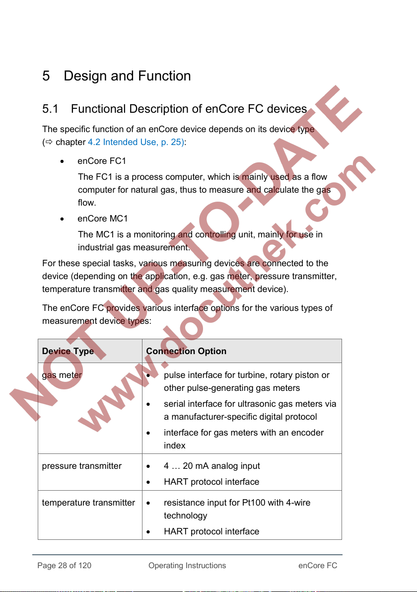
For these special tasks, various measuring devices are connected to the
device (depending on the application, e.g. gas meter, pressure transmitter,
temperature transmitter and gas quality measurement device).
The enCore FC provides various interface options for the various types of
measurement device types:
Device Type Connection Option
gas meter • pulse interface for turbine, rotary piston or
other pulse-generating gas meters
• serial interface for ultrasonic gas meters via
a manufacturer-specific digital protocol
• interface for gas meters with an encoder
index
pressure transmitter • 4 … 20 mA analog input
• HART protocol interface
temperature transmitter • resistance input for Pt100 with 4-wire
technology
• HART protocol interface
Page 28 of 120
enCore FC
Page 29

5 Design and Function
enCore FC
Operating Instructions
Page 29 of 120
Device Type Connection Option
gas quality
measurement devices
• serial interface
• LAN interface
Table 1: Interface options
5.1.1 Number of Streams and their Flow Directions
The number of streams and their flow directions are variable since device
hardware and software can be extended. This number depends upon the
number of board slots available, individual hardware settings and the soft-
ware configuration.
5.1.2 International Standards
Flow Computers of the enCore FC device series support the following
international standards for the calculation of the gas characteristics which
are used for flow conversion. Which standards are supported in detail varies
according to device type:
Value Selectable Calculation Standard
compressibility • AGA8-92 DC (ISO 12213-2)
• SGERG-88 (ISO 12213-3)
• AGA-NX19 mod
• AGA-NX19 mod BR.KOR.3H
• AGA-NX19 GOST
• GOST 30319.2-2015
• GOST 30319.3-2015
gas density, relative density • AGA8-92 DC (ISO 12213-2)
• ISO 6976
• GOST 30319.3-2015
heating value, Wobbe index • ISO 6976
Page 30
Design and Function 5
Page 30 of 120
Operating Instructions
enCore FC
Table 2: International standards
Depending on the field of application, the enCore FC supports other
European or international standards as well.
5.2 Device Description
The enCore FC is housed in a 19“ housing with 1/3 overall width (max. 4
process boards) or 1/2 overall width (max. 7 process boards).
screen as well as the 2 function keys and 5 navigation keys for operation are
located on the front panel. In addition, the USB connection, security switch
and 2 status LEDs are located on the front panel.
At the rear side of the device, the CPU board provides a LAN interface and
two RS232/RS422/RS485 serial interfaces. Devices with protocol interfaces
can be connected to these interfaces, e.g. gas quality measuring devices.
Various other I/O boards can be mounted from the rear side of the device.
The maximum number of boards depends upon the housing design. A
maximum of four process boards can be installed in a device with 1/3 overall
width, while a maximum of seven can be installed in a device with 1/2 overall
width.
6 The touch
The configuration of the I/O board equipment is variable. In principle, any I/O
board can be inserted into any slot. There might be individual limitations de-
pending on the type of the board.
The following board types are currently available:
6
chapter 9.6 Housing dimensions (p. 93)
• ExMFE5 Ex input board
• MFE7 input board
• MFA8 output board
• digital communication boards MSER4
• digital communication boards ESER4
Page 31

5 Design and Function
enCore FC
Operating Instructions
Page 31 of 120
1
2
3
4
5
6
7
5
7
2
6
1 2 4
3
For a detailed description of the process boards and possible limitations for
the board equipment refer to chapter 5.5 Available Process Boards
(p. 40).
5.3 Operation Panel
Fig. 5-1: enCore FC operation panel – example enCore FC1
navigation keys
function keys
touch screen
security switch
power-LED
status-LED
USB connection for PC connection
Page 32

Design and Function 5
Page 32 of 120
Operating Instructions
enCore FC
2
3
4
5
1
2
3
4
5
5.3.1 Device Keys
Two function keys are arranged below the touch screen. Pressing one of
these keys activates the display button positioned directly over it.
1
up
down
left
right
Fig. 5-2: Navigation keys
enter
The navigation keys (up, down, left, right, enter) are provided for navigation
purposes in device menus and displays. They provide an alternative option
to the touch screen for operating the display. An acoustic signal is given out
when a key is pressed.
5.3.2 Touch Screen
All the key functions can be executed from the touch screen. An acoustic
signal indicates that a function was activated.
Re-calibration of the touch screen
Elster calibrates the touch screen before delivery. In case a re-
calibration should be necessary, select in the home display of
the device Info – Display calibration and follow the in-
structions on the device.
You can cancel he calibration at any time with the back key
and then restart the calibration.
In case of erroneous calibration you can always use the function
and navigation keys of the device.
Page 33

5 Design and Function
enCore FC
Operating Instructions
Page 33 of 120
or AFB ...
5.3.3 Operation and Navigation within the Display
Display test
Using the display test, you can check whether the device display of the
enCore FC is working correctly.
To run the display test, …
► … switch to the home display if necessary.
► Double-click the symbol to open the Info display.
► Start the test with the action Display test.
During test mode, all pixels of the login area are alternately black and
white.
► End the test with or .
Different types of device displays
Main display is the name of the first display of an AFB or a functionality of
the basic system; it shows the most important results of this functionality.
Depending on the AFB or functionality, further information is displayed in
subordinate device displays.
The basic display is displayed immediately after the device is started. If no
operation is performed during a preset time, the device switches back to the
basic display automatically. For some device types, it is parameterizable
which display is used as basic display.
Changing the „basic display“
For most device types (e.g. devices that are intended for the use
in legal metrology), the basic display is fixed. In case that the
basic display is not fixed, you can parameterize it in enSuite for a
device parameterization in node Displays on tab Basic
display editor:
To define a display as basic display, select …
► … from the 1
st
dropdown list Basic display the desired SFB
Page 34

Design and Function 5
Page 34 of 120
Operating Instructions
enCore FC
► ... and from the 2
nd
dropdown list Basic display the display of
this SFB or AFB.
► If necessary, adjust the time (in seconds) without any
operation before ...
• ... the device switches back to the basic display in
parameter Go to basic display after <x> sec.
• ... the brightness of the screen is reduced in parameter
Duration bright display <x> sec.
• ... the screen is turned off in parameter Duration
dimmed display <x> sec.
Home is a special display and shows the software structure of the device. In
enSuite you add further entries to the home display in the parameter
branch Displays on tab Menu-editor – Home fest. Single software
modules (like e.
easily accessible (e.
g. AFBs) and further selected functionalities, which shall be
g. time or language setting), are represented with small
symbols in this display. The symbols are labelled with the name of the
corresponding functionality.
AFBs are labelled with their user-defined names, if parameterized –
otherwise the default name is displayed.
During parameterization, you can group AFBs in user-defined structures.
Each group of AFBs is displayed in a folder <Group name> in the home
display .
Navigating via touch-screen
In general
Two buttons are displayed at the bottom of the touch screen. Depending on
the context, you can use the symbols and or and .
The function of the buttons is as follows:
You switch directly to the home display.
You switch directly to the basic display.
Page 35
5 Design and Function
enCore FC
Operating Instructions
Page 35 of 120
You switch back to the calling display, i.
e. the display that was
previously opened.
The basic display can always be reached with a maximum of two steps –
either by pressing and successively, or by pressing , if this button
is displayed directly.
If the buttons are marked with the checkmark or the X symbol , a user
action has been performed previously (e.
g. setting the system time) and the
device is waiting for a confirmation by the user. User actions can be
accepted with or discarded with .
Navigation options in the „home“ display
You open a folder by touching its symbol in the display; the AFBs grouped in
that folder are shown subsequently.
After having touched the symbol of an AFB or any other selected func-
tionality, the corresponding main display is shown.
Navigation options in other displays
Most device displays show measurement results, status information or
settings.
When operating an enCore FC device, hyperlinks and actions are distin-
guished: Use hyperlinks to navigate through the device's displays and use
actions to perform a specific functionality. Both hyperlinks and actions are
presented in the display with a blue font color and underlined.
If a display contains more lines than can be presented at once, an orange
scroll bar appears at the right edge of the screen.
You can scroll the contents of the display up or down by moving your finger
vertically across the display area (vertical "wiping").
Navigation via keys
The buttons at the lower edge of the touch screen can alternatively be
activated by pressing the associated (hardware) keys located directly
underneath.
Page 36
Design and Function 5
Page 36 of 120
Operating Instructions
enCore FC
You can activate the controls located at the top of the touch screen by using
the [Up], [Down], [Left] and [Right] keys, and activate them by pressing
[Enter].Use the [Up] and [Down] keys to scroll through the contents of a
display. ( chapter 5.3.1 Device Keys, S. 32)
5.3.4 Security Switch
The security switch is a sealable rotary switch. The security switch is closed
by turning it clockwise until it stops.
The security switch is part of the enCore concept for limiting user rights. A closed
security switch can prevent certain actions of the user (e.g. changing certain
parameters or software downloads of legally relevant (fiscal) or operative (non-
fiscal) firmware module).
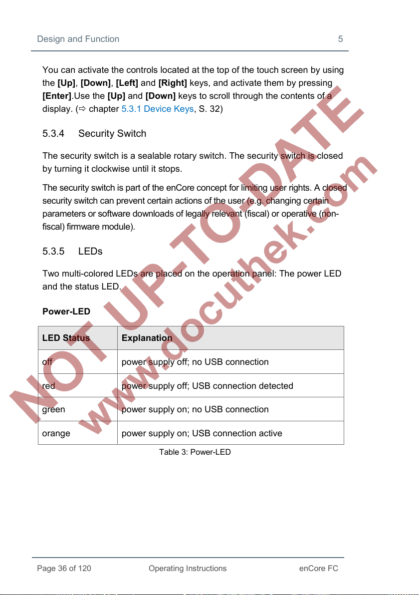
5.3.5 LEDs
Two multi-colored LEDs are placed on the operation panel: The power LED
and the status LED.
Power-LED
LED Status Explanation
off power supply off; no USB connection
red power supply off; USB connection detected
green power supply on; no USB connection
orange power supply on; USB connection active
Table 3: Power-LED
Page 37
5 Design and Function
enCore FC
Operating Instructions
Page 37 of 120
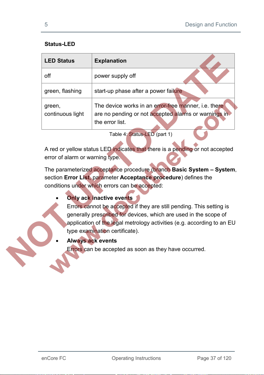
Status-LED
LED Status Explanation
off power supply off
green, flashing start-up phase after a power failure
green,
continuous light
The device works in an error-free manner, i.e. there
are no pending or not accepted alarms or warnings in
the error list.
Table 4: Status-LED (part 1)
A red or yellow status LED indicates that there is a pending or not accepted
error of alarm or warning type.
The parameterized acceptance procedure (branch Basic System – System,
section Error List, parameter Acceptance procedure) defines the
conditions under which errors can be accepted:
• Only ack inactive events
Errors cannot be accepted if they are still pending. This setting is
generally prescribed for devices, which are used in the scope of
application of the legal metrology activities (e.g. according to an EU
type examination certificate).
• Alwa ys ack events
Errors can be accepted as soon as they have occurred.
Page 38
Design and Function 5
Page 38 of 120
Operating Instructions
enCore FC
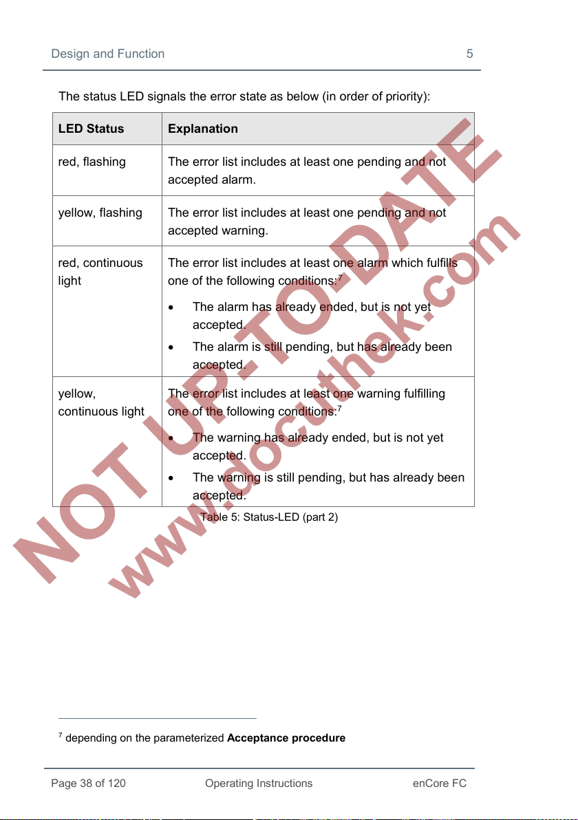
The status LED signals the error state as below (in order of priority):
LED Status Explanation
red, flashing The error list includes at least one pending and not
accepted alarm.
yellow, flashing The error list includes at least one pending and not
accepted warning.
red, continuous
light
yellow,
continuous light
The error list includes at least one alarm which fulfills
7
one of the following conditions:
• The alarm has already ended, but is not yet
accepted.
• The alarm is still pending, but has already been
accepted.
The error list includes at least one warning fulfilling
one of the following conditions:
7
• The warning has already ended, but is not yet
accepted.
• The warning is still pending, but has already been
accepted.
Table 5: Status-LED (part 2)
7
depending on the parameterized Acceptance procedure
Page 39

5 Design and Function
enCore FC
Operating Instructions
Page 39 of 120
1
2
3
4
1
2
5.4 Interfaces (Rear Side of Device)
1
Fig. 5-3: Rear of device (example 1/3 overall width)
LAN interface (Ethernet network)
serial interfaces
24 V DC power supply
optional process boards
Page 40

Design and Function 5
Page 40 of 120
Operating Instructions
enCore FC
5.5 Available Process Boards
The configuration of the I/O board assignment is variable. In principle, any
I/O board can be inserted into any slot. If there are any kind of technical
limitations – depending on the board type, they are listed in the following
chapters (descriptions individual boards):
6.3 Installation and Conversion of Process Boards (p. 48)
This chapter describes the ways you can change the I/O board
equipment.
6.4 Connection Diagrams (p. 54)
This chapter includes connection diagrams for typical applications.
5.5.1 ExMFE5 Process Board
WARNING!
Risk of explosion
A risk of explosion exists if lines are connected to the
ExMFE5 board while the device is connected to the power
supply!
The transmitter-, pulse- and signal lines are connected only to the
ExMFE5 board if the enCore FC is connected in a voltage-free
manner.
Page 41

5 Design and Function
enCore FC
Operating Instructions
Page 41 of 120
WARNING!
Risk of explosion
A risk of explosion exists if the enCore FC (FC1 or MC1) is
improperly assembled and connected!
• The enCore FC must be installed outside of Ex zones 0, 1
and 2.
• Assemblies which are authorized as associated category ib
electrical equipment with intrinsically safe electrical circuits in
accordance with EN 60079-11 can be installed in the enCore
FC, e.g. input boards with the label ExMFE5. The enCore FC
is therefore suitable for connecting to transmitters, pulse and
signal sensors that are located in the potentially explosive
area e.g. in zone 1. A mixed connection of intrinsically safe
and non-intrinsically safe circuits is not permitted for these
assemblies.
• Only measurement transmitters and pulse sensors that follow
at least the requirements of the intrinsically safe protection
class [Ex ib Gb] II C may be connected to the ExMFE5
assembly terminals provided for that purpose.
• When using input boards of ExMFE5 type, it is not permitted
(according to the EC type examination certificate ATEX) to
include more than one ExMFE5 board (i.e. more than one
associated apparatus) into the same intrinsically safe circuit.
• All signals from the potentially explosive area (zone 0,
zone 1, zone 2) must be regulated using suitable Ex isolators,
if they are connected to some other assembly group that is
not the input board ExMFE5
• The regulations in the relevant standards, especially
EN 60079-0, EN 60079-11, EN 60079-17 and EN 60079-25,
must be obeyed unconditionally.
Page 42

Design and Function 5
Page 42 of 120
Operating Instructions
enCore FC
Comply with the safety- and risk instructions of the ExMFE5
input boards!
4.1 General Safety Instructions (p. 23)
6.1 Line Connection (p. 45)
The process board ExMFE5 is an “associated electrical
equi
pment” according to EN50020, which provides five
intrinsically safe input circuits of the category [Ex ib Gb] II C:
• Three NAMUR inputs (Z1+/Z1-, Z2+/Z2-, Z3+/Z3-) for
signals, LF pulses and HF pulses.
As an alternative, the first channel is suitable for
connecting an encoder index.
• A resistance input in 4-wire technology (I+/U+/U-/I-).
• An analog current input 4 … 20mA (P+/P-), alter-
natively usable as a HART interface.
Fig. 5-4
Page 43

5 Design and Function
enCore FC
Operating Instructions
Page 43 of 120
5.5.2 MFE7 Process Board
The process board MFE7 provides seven input circuits:
• A resistance input in 4-wire technology
(RI+/RU+/RU-/RI-).
• Two analog current inputs (A1+/A1-, A2+/A2-) in
operational modes 0…20 mA or 4...20 mA, alter-
natively usable as a HART interface.
• Three pulse inputs or signal inputs (D1, D2, D3/GND)
for signals, LF pulses or HF pulses. As an alter-
native, the third channel (D3/GND) is suitable for
connecting an encoder index. As an alternative,
channels 2 and 3 (D2, D3/GND) can be used as a
frequency input
• A RS485 serial interface (RSA/RSB/GND).
Fig. 5-5
5.5.3 MSER4 Process Board
The process board MSER4 provides for four serial interfaces,
each for one protocol channel (CH1, CH2, CH3, CH4). Every
protocol channel alternatively supports RS485, RS422 or
RS232.
For a device in 1/3 overall width, a maximum of
one MSER4 board can be installed in slot 4 only.
For a device in 1/2 overall width, up to two
MSER4 boards can be installed in slots 6 and 7
only.
Fig. 5-6
Page 44

Design and Function 5
Page 44 of 120
Operating Instructions
enCore FC
5.5.4 ESER4 Process Board
The process board ESER4 provides for three serial interfaces,
each for one protocol channel (CH1, CH2, CH3). Every
protocol channel alternatively supports RS485, RS422 or
RS232. Moreover, one LAN interface (Ethernet network) is
available.
For a device in 1/3 overall width, a maximum of one
ESER4 board can be installed in slot 4 only. For a
device in 1/2 overall width, up to two ESER4 boards
can be installed in slots 6 and 7 only.
Fig. 5-7
5.5.5 MFA8 Process Board
The process board MFA8 provides eight output circuits:
• One digital message output (D1a/D1b).
• Three digital outputs (D2+/D2-, D3+/D3-, D4+/D4-)
for messages, trigger outputs or LF pulses.
• Four analog outputs (I1, I2, I3, I4/I-) 0... 20 mA or
4 … 20 mA for measurements.
Fig. 5-8
Page 45

Page 45 of 120
Operating Instructions
enCore FC
6 Assembly Instructions
The enCore FC is provided for assembly within a 19" cabinet, and is
available in either a 1/3 overall width or 1/2 overall width model. Compliance
with the device's installation depth of 170 mm (with plugs approx. 220 mm) is
necessary so the connection terminals located on the rear of the device
remain accessible.
The enCore FC must be installed in an Ex free plant room
(electrical room) outside of Ex zones 0, 1 and 2, in accordance
with protection class IP 20.
It is recommended that the enCore FC be installed in a swivel
frame.
6.1 Line Connection
WARNING!
Risk of explosion
A risk of explosion exists if lines are connected to the
ExMFE5 board while the device is connected to the power
supply!
Only connect transmitter, pulse and signal lines to the ExMFE5
board when power supply of the enCore FC is disconnected
completely.
Page 46

Assembly Instructions 6
Page 46 of 120
Operating Instructions
enCore FC
ATTENTION!
Risk of short circuit
The enCore FC device can be damaged if lines are connected
while the device is connected to the power supply.
Always make sure the enCore FC is free of voltage before making
any changes to device wiring or before connecting sensor, supply,
signal or data lines.
The transmitter, pulse, signal and data lines are connected to the enCore FC
by using plug-in screw terminals that are located in a cable housing. Fixed
screw terminals are used for the power supply connection.
Special attention must be paid to the intrinsically safe electrical circuits.
Before switching on the power supply, the operator must ensure that the
plug connections for the gas meter, pressure and temperature inputs of the
ExMFE5 input board are inserted, since this is the only way the minimum
distance of 50 mm required in the relevant guidelines can be maintained.
The relevant installation guidelines must be observed when arranging the
wiring.
The device lines must be free of tensile stress and must be provided with a
kink protection if the enCore FC is being installed in a swivel frame.
Enough length must be allocated to cables so no tensile stress occurs in
cables when the swivel frame is opened up.
It is recommended that the lines be placed on transfer terminals in a switch
cabinet, and then be connected with the enCore FC from that point.
However, these terminals must sometimes fulfill Ex regulations, and must
also be sealable if applicable, for example in order to fulfill the requirements
of an applicable approval.
Page 47

6 Assembly Instructions
enCore FC
Operating Instructions
Page 47 of 120
Hazard ous A rea Safe A rea enCore device
CPU board
24V
0V
PE
+24V DC
Fuse 1A slow
0V
6.2 Power Supply and Grounding
Fig. 6-1: Power supply
The enCore FC must be operated with a rated voltage of 24 V DC (max.
permissible range: 20.4 V to 28.8 V).
The 24 V power supply is connected via the (+) and (–) terminals at the rear
of the device, and must be protected externally using a 1A time-delay fuse.
It is recommended to operate the process computer in conjunction with an
uninterruptible power supply. Its design must comply with EN 60654-2 for
direct current; nominal voltage 24 V DC, permitted range 20.4 V DC to
28.8 V DC, switching time not exceeding 10 ms. The external power supply
must provide at least 12 W power. With a mains voltage of 100 V up to
230 V for the uninterruptible power supply, the switching time must not be
greater than a mains period (50 or 60 Hz), based on the nominal value of the
mains frequency.
The device is protected internally by means of a self-resetting over-current
protection component.
Page 48

Assembly Instructions 6
Page 48 of 120
Operating Instructions
enCore FC
The grounding system is connected to the power supply socket PE for
potential equalization.
6.3 Installation and Conversion of Process Boards
The process board configuration of the device is in correspondence with the
order at the time of delivery. Owing to the modular hardware concept it is
now possible to insert additional process boards in free board slots even
later or to change the compilation of the process boards.
For safety reasons, any modifications of the process board
configuration should be carried out only by the manufacturer's
service department or by an appropriately trained specialist
working for the plant operator.
The housing of the device must be opened in order to add or
change process boards. The presence of a metrology expert may
be required for this purpose when the device is being used within
the scope of legal metrology.
ATTENTION!
Risk of short circuit
The device may damage if it is opened in case of connected
power supply.
Always make sure the enCore FC is free of voltage before
opening the device.
Page 49
6 Assembly Instructions
enCore FC
Operating Instructions
Page 49 of 120
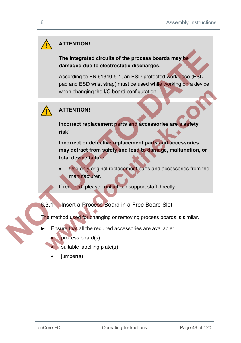
ATTENTION!
The integrated circuits of the process boards may be
damaged due to electrostatic discharges.
According to EN 61340-5-1, an ESD-protected workplace (ESD
pad and ESD wrist strap) must be used while working on a device
when changing the I/O board configuration.
ATTENTION!
Incorrect replacement parts and accessories are a safety
risk!
Incorrect or defective replacement parts and accessories
may detract from safety and lead to damage, malfunction, or
total device failure.
• Use only original replacement parts and accessories from the
manufacturer.
If required, please contact our support staff directly.
6.3.1 Insert a Process Board in a Free Board Slot
The method used for changing or removing process boards is similar.
► Ensure that all the required accessories are available:
• process board(s)
• suitable labelling plate(s)
• jumper(s)
Page 50

Assembly Instructions 6
Page 50 of 120
Operating Instructions
enCore FC
A
A
► If necessary, install or update to the next enSuite on the work computer
( enSuite installation guide
► Read out the enCore FC device's parameterization with enSuite.
► Disconnect the power supply.
► Remove all the external cable connections from the device.
► Remove the 4 mounting screws present on the rear of the device
8).
(Positions A).
8
The installation guide is located on the enSuite installation CD. Alternatively, you can
download the PDF from the Elster website in the software downloads section:
www.elster-instromet.com/en/software-downloads.
Fig. 6-2: Rear side of the device (example),
mounting screws are removed
Page 51
6 Assembly Instructions
enCore FC
Operating Instructions
Page 51 of 120
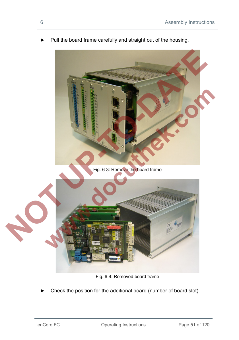
► Pull the board frame carefully and straight out of the housing.
Fig. 6-3: Remove the board frame
Fig. 6-4:
Removed board frame
Check the position for the additional board (number of board slot).
►
Page 52

Assembly Instructions 6
Page 52 of 120
Operating Instructions
enCore FC
(slot no.)
Set up the board number on the board
Note that the number of the board slot as well as the board
number on the board must be set; this is essential for further
functioning of the internal I/O bus communication.
► Insert the relevant jumpers in the suitable pin connector in order to
define the number on the board ( Fig. 6-5 and 6-6).
=
jumper
board position
►
Remove the cover plate of the respective slot (2 screws).
► Insert the board with the side meant for the process connection in the
1 2 3 4 5 6 7
Fig. 6-5: Pin connector with jumper positions
slot on the rear panel (blue plug for Ex boards, otherwise green plug,
Fig. 6-2).
Page 53
6 Assembly Instructions
enCore FC
Operating Instructions
Page 53 of 120
C B
C
B
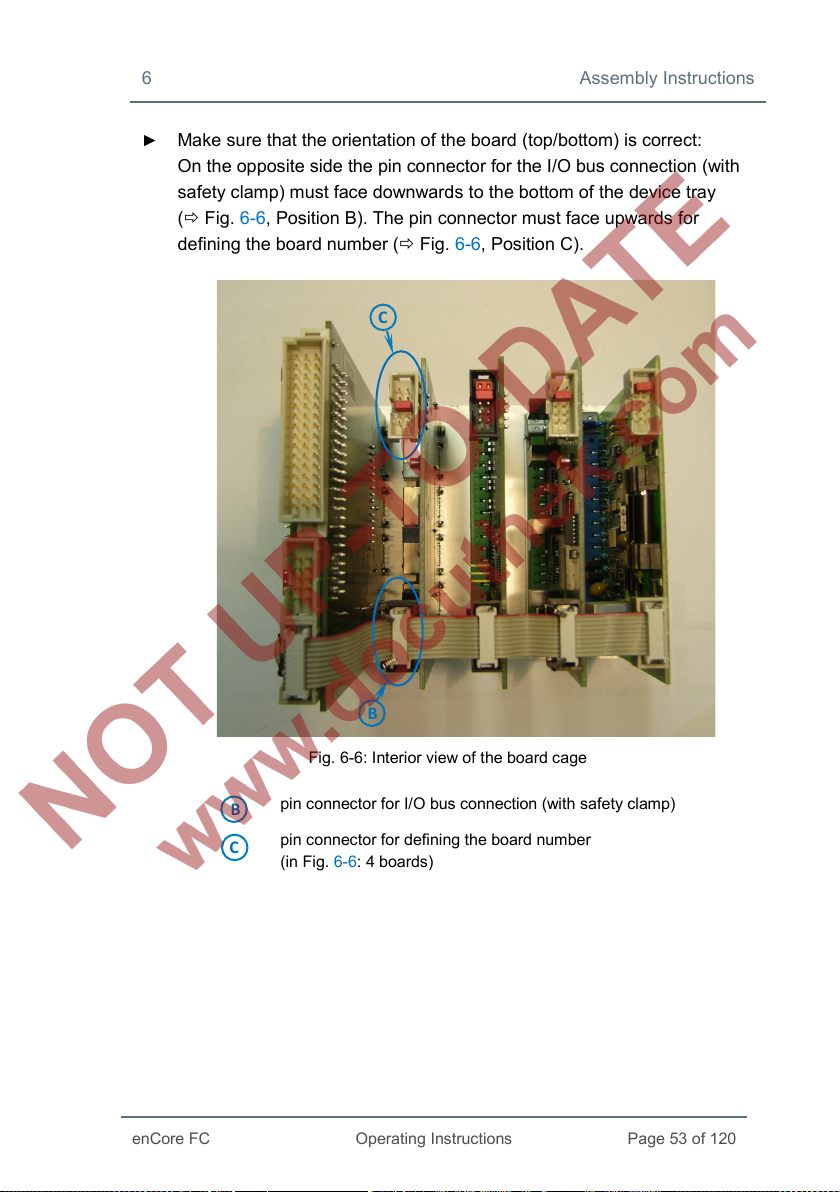
► Make sure that the orientation of the board (top/bottom) is correct:
On the opposite side the pin connector for the I/O bus connection (with
safety clamp) must face downwards to the bottom of the device tray
( Fig. 6-6, Position B). The pin connector must face upwards for
defining the board number ( Fig. 6-6, Position C).
Fig. 6-6: Interior view of the board cage
pin connector for I/O bus connection (with safety clamp)
pin connector for defining the board number
(in Fig. 6-6: 4 boards)
Page 54
Assembly Instructions 6
Page 54 of 120
Operating Instructions
enCore FC
► Position the labelling plate of the board on the rear side of the device
and screw the board firmly on to the labelling plate.
► Insert the plug for the internal I/O bus on the other side of the board.
The safety clamp closes automatically. Check whether all the other bus
plugs are still plugged in properly.
► Re-insert the board frame carefully inside the device. Press gently on
the board frame in order to re-establish a connection between CPU and
the display board.
► Close the device with the help of the 4 mounting screws
(Positions A in Fig. 6-2).
► Restore all external cable connections with enCore FC.
► Connect the power supply.
► Use the enSuite to edit the imported parameterization by taking into
consideration the new board configuration.
Add the new board to the parameterization (parameter branch Basic
System – I/O boards, section Board <x>) and adjust all settings for its
process connection.
► Transfer the edited parameterization to the device.
Details on parameterization
For details on the parameterization procedure refer to volume
“Configuration of Device Software” of the enCore FC manual.
6.4 Connection Diagrams
This section shows connection diagrams for those measurement devices that
are typically connected to an enCore FC flow computer (e.g. temperature and
pressure transmitter, gas meter and gas quality measurement devices).
Moreover, typical connection diagrams for processing devices such as station
control or remote transfer device are illustrated here.
Page 55

6 Assembly Instructions
enCore FC
Operating Instructions
Page 55 of 120
Minimum requirements
If a special setting is required for connecting a specific board or a
specific board channel with a measuring device, you get only the
minimum required settings below the respective connection
diagram.
For details on parameterization refer to the online help.
6.4.1 General Recommendations for Signal and Data Cable
Signal Connection
The following standard minimum requirements for the used type of cable are
recommended for the signal connection with external transmitters and sen-
sors as well as for the signal connection of external devices:
• signal cable with a line-to-line capacity smaller than 120 pF/m and
an inductance smaller than 0.7 µH/m
• Wire diameter greater or equal to 0.5 mm
ding to the application, stranded cable, shielded together. Screen at
just one place (preferably on enCore FC) connected with PE.
• The maximum cable length is dependent on the type of the signal;
refer to the following section for exact specifications.
2
, number of wires accor-
Data Communication Connection
The following standard minimum requirements for the used type of cable are
recommended for the data communication connection with external sensors
as well as for the data communication connection of external devices accor-
ding to RS232, RS422 or RS485:
• signal cable with a line-to-line capacity smaller than 120 pF/m and
an inductance smaller than 0.7 µH/m
• Wire diameter greater or equal to 0.25 mm
2
, number of wires accor-
ding to the application, stranded cable, shielded together. Screen at
just one place (preferably on enCore FC) connected with PE.
Page 56
Assembly Instructions 6
Page 56 of 120
Operating Instructions
enCore FC
• The maximum cable length is 30 m for RS232, and 500 m for
RS422 and RS485.
RS485
According to RS485, resistors are required for resting potential generation at
any places in case of data communication connections, for every 470 Ω
between R/TA and +U and also between R/TB and SGND. Other bus resis-
tors at every 120 Ω between R/TA and R/TB on both the physical ends of the
cable are recommended for cable length from 200 m onwards.
Ethernet
A standard type of cable is recommended for data communication connec-
tion via Ethernet according to Category 5 (Cat 5), the maximum cable length
is 100 m.
Page 57
6 Assembly Instructions
enCore FC
Operating Instructions
Page 57 of 120
Hazard ous A rea Safe Area enCore device
ExMFE 5 board
I+
U+
U−
I−
SH
Pt100, EEx i
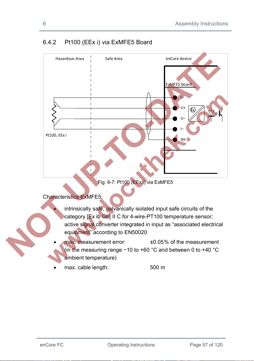
6.4.2 Pt100 (EEx i) via ExMFE5 Board
Fig. 6-7: Pt100 (EEx i) via ExMFE5
Characteristics ExMFE5:
• intrinsically safe, galvanically isolated input safe circuits of the
category [Ex ib Gb] II C for 4-wire-PT100 temperature sensor;
active signal converter integrated in input as “associated electrical
equipment” according to EN50020
• max. measurement error: ±0.05
(in the measuring range −10 to +60 °C and between 0 to +40 °C
ambient temperature)
• max. cable length: 500 m
% of the measurement
Page 58

Assembly Instructions 6
Page 58 of 120
Operating Instructions
enCore FC
Hazard ous A rea Safe Area enCore device
MFE7 bo ard
RI+
RU+
RU−
RI−
SH
Pt100, EEx d
6.4.3 Pt100 (EEx d) via MFE7 Board
Fig. 6-8: Pt100 (EEx d) via MFE7
Characteristics MFE7:
• a galvanically isolated input safe circuit for 4-wire-PT100
temperature sensor
• max. measurement error: ±0.05
(in the measuring range −40 to +120 °C and between −10 to +55 °C
ambient temperature)
• max. cable length: 500 m
% of the measurement
Page 59

6 Assembly Instructions
enCore FC
Operating Instructions
Page 59 of 120
Ha zardous Area Safe Area
enCore device
ExMFE 5 board
P+
SH
Analog pressure
transmitter
4...20 mA, EEx i
P−
6.4.4 Analog Measurement Transmitter (EEx i) via ExMFE5 Board
Fig. 6-9: analog pressure transmitter (EEx i) via ExMFE5 – example
Characteristics ExMFE5:
• intrinsically safe, galvanically isolated input safe circuits of the
category [Ex ib Gb] II C for transmitter with 4 ... 20mA interface
• active signal converter integrated of the category “associated
electrical equipment” according to EN50020 in input:
− open-curcuit voltage: approx. 18 V
− voltage at 20mA: approx. 10.6 V
− max. load: 300 Ω
• max. measurement error: ±0.05
(in the measuring range 4 to 20 mA and between 0 to +40 °C
ambient temperature)
• max. cable length: 500 m
% of the measurement
Page 60

Assembly Instructions 6
Page 60 of 120
Operating Instructions
enCore FC
Ha zardous Area Safe Area enCore device
MFE7 bo ard
A1+ or A2+
A1− or A2−
SH
Analog pressure
transmitter
4...20 mA, EEx d
(so ur ce m od e)
Hints on parameterization
Branch <device> – Basic System – I/O boards –
Board <x>: ExMFE5
Set the following value:
• channel P1+ P1−: type Current input
6.4.5 Analog Measurement Transmitter (EEx d) via MFE7 Board (without barrier)
Fig. 6-10: Analog pressure transmitter (EEx d) via MFE7 – example
Characteristics MFE7:
• a galvanically isolated input safe circuit with 4 ... 20 mA interface:
− open-circuit voltage: approx. 21 V
− voltage at 20 mA: approx. 12.6 V
− max. load: 600 Ω
• max. measurement error: ±0.05
(in the measuring range 4 ... 20 mA and between −10 to +55 °C
ambient temperature)
% of the measurement
Page 61

6 Assembly Instructions
enCore FC
Operating Instructions
Page 61 of 120
Ha zardous Area Safe Area
enCore device
MFE7 bo ard
A1+ or A2+
A1− or A2−
SH
Analog pressure
transmitter
4...20 mA, EEx i
Isola ted cu rrent
repeater barrier
(sink mode)
+
−
(so ur ce m od e)
• max. cable length: 500 m
Hints on parameterization
Branch <device> – Basic System – I/O boards –
Board <x>: MFE7
Set the following values:
• channel A1+ A1− or A2+ A2−: type Current input
• parameter Power supply: value On (source mode)
6.4.6 Analog Measurement Transmitter (EEx i) via MFE7 Board (barrier in sink mode)
Characteristics MFE7:
Fig. 6-11: Analog pressure transmitter (EEx i) via MFE7 – example
• a galvanically isolated input safe circuit with 4 ... 20 mA interface:
− open-circuit voltage: approx. 21 V
− voltage at 20mA: approx. 12.6 V
− max. load: 600 Ω
Page 62

Assembly Instructions 6
Page 62 of 120
Operating Instructions
enCore FC
Ha zardous Area Safe Area
enCore device
MFE7 bo ard
A1+ or A2+
A1− or A2−
SH
Analog pressure
transmitter
4...20 mA, EEx i
0V 24V
Isola ted cu rrent
repeater barrier
(so ur ce m od e)
+
−
(sink mode)
• max. measurement error: ±0.05 % of the measurement
(in the measuring range 4 ... 20 mA and between −10 to +55 °C
ambient temperature)
• max. cable length: 500 m
Hints on parameterization
Branch <device> – Basic System – I/O boards –
Board <x>: MFE7
Set the following values:
• channel A1+ A1− or A2+ A2−: type Current input
• parameter Power supply: value On (source mode)
6.4.7 Analog Measurement Transmitter (EEx i) via MFE7 Board (barrier in source mode)
Fig. 6-12: Analog pressure transmitter (EEx i) via MFE7 – example
Characteristics MFE7:
• a galvanically isolated input safe circuit with 4 ... 20 mA interface:
Page 63

6 Assembly Instructions
enCore FC
Operating Instructions
Page 63 of 120
Ha zardous Area Safe Area enCore device
ExMFE 5 board
P+
SH
HART pressure
transmitter, EEx i
HART temperature
transmitter, EEx i
HART
comm unicator
P−
− load: approx. 50 Ω
• max. measurement error: ±0.05
% of the measurement
(in the measuring range 4 ... 20 mA and between −10 to +55 °C
ambient temperature)
• max. cable length: 500 m
Hints on parameterization
Branch <device> – Basic System – I/O boards –
Board <x>: MFE7
Set the following values:
• channel A1+ A1− or A2+ A2−: type Current input
• parameter Power supply: value Off (sink mode)
6.4.8 HART Measurement Transmitter (EEx i) via ExMFE5 Board
Fig. 6-13: HART pressure and temperature transmitter (EEx i) via ExMFE5 – example
Page 64

Assembly Instructions 6
Page 64 of 120
Operating Instructions
enCore FC
Characteristics ExMFE5:
• an intrinsically safe, galvanically isolated input safe circuits of the
category [Ex ib Gb] II C for transmitter with HART interface
• an active signal and protocol converter integrated in input as
“associated electrical equipment” according to EN50020
− open-circuit voltage: approx. 18 V
− voltage at 20 mA: approx. 10.6 V
− max. load: 300 Ω
• max. 4 transmitters:
thereof max. 1 transmitter in burst mode
9, 10
• max. cable length: 250 m
Hints on parameterization
Branch <device> – Basic System – I/O boards –
Board <x>: ExMFE5
Set the following value:
• channel P1+ P1−: type HART channel
9
Up to and including basic system version 03-24, you could use either up to
4 × transmitters in multidrop mode or 1 × transmitters in burst mode.
10
Burst mode is not supported by all transmitters.
With this, the operating mode of the channel is set correctly for
connecting the HART transmitters.
If you are using the basic system version 03-24 and earlier, refer
to FAQ 11.2 Limitations for multidrop and burst mode up to basic
system version ≤ 03-24 (p. 116).
Page 65
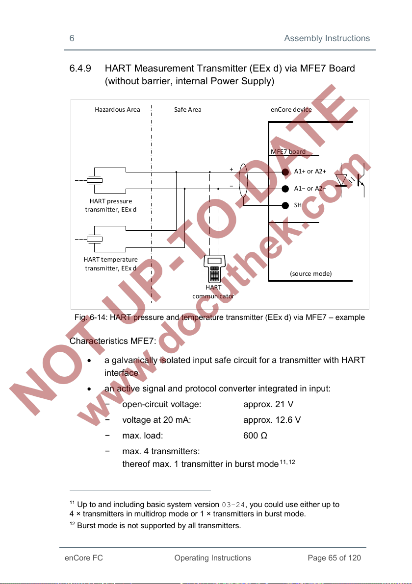
6 Assembly Instructions
enCore FC
Operating Instructions
Page 65 of 120
Ha zardous Area Safe Area enCore device
MFE7 bo ard
A1+ or A2+
A1− or A2−
SH
HART pressure
transmitter, EEx d
HART temperature
transmitter, EEx d
HART
comm unicator
+
−
(so ur ce m od e)
6.4.9 HART Measurement Transmitter (EEx d) via MFE7 Board (without barrier, internal Power Supply)
Fig. 6-14: HART pressure and temperature transmitter (EEx d) via MFE7 – example
Characteristics MFE7:
• a galvanically isolated input safe circuit for a transmitter with HART
interface
• an active signal and protocol converter integrated in input:
− open-circuit voltage: approx. 21 V
− voltage at 20 mA: approx. 12.6 V
− max. load: 600 Ω
− max. 4 transmitters:
thereof max. 1 transmitter in burst mode
11
Up to and including basic system version 03-24, you could use either up to
ransmitters in multidrop mode or 1 × transmitters in burst mode.
4 × t
12
Burst mode is not supported by all transmitters.
11, 12
Page 66

Assembly Instructions 6
Page 66 of 120
Operating Instructions
enCore FC
• max. cable length: 250 m
Hints on parameterization
Branch <device> – Basic System – I/O boards –
Board <x>: MFE7
Set the following values:
• channel A1+ A1− or A2+ A2−: type HART channel
• parameter Power supply: value On (source mode)
With this, the operating mode of the channel is set correctly for
connecting the HART transmitters.
If you are using the basic system version 03-24 and earlier, refer
to FAQ 11.2 Limitations for multidrop and burst mode up to basic
system version ≤ 03-24 (p. 116).
Page 67

6 Assembly Instructions
enCore FC
Operating Instructions
Page 67 of 120
Ha zardous Area Safe Area enCore device
MFE7 bo ard
A1+ or A2+
A1− or A2−
SH
HART pressure
transmitter, EEx d
HART temperature
transmitter, EEx d
HART
comm unicator
0V24V
+
−
(sink mode)
6.4.10 HART Measurement Transmitter (EEx d) via MFE7 Board (without barrier, external Power Supply)
Fig. 6-15: HART pressure and temperature transmitter (EEx d) via MFE7 – example
Characteristics MFE7:
• a galvanically isolated input safe circuit for a transmitter with HART
interface
− load: approx. 300 Ω
• protocol converter integrated in input:
max. 4 transmitters:
thereof max. 1 transmitter in burst mode
• max. cable length: 250 m
13
Up to and including basic system version 03-24, you could use either up to
ransmitters in multidrop mode or 1 × transmitters in burst mode.
4 × t
14
Burst mode is not supported by all transmitters.
13, 14
Page 68

Assembly Instructions 6
Page 68 of 120
Operating Instructions
enCore FC
Hints on parameterization
Branch <device> – Basic System – I/O boards –
Board <x>: MFE7
Set the following values:
• channel A1+ A1− or A2+ A2−: type HART channel
• parameter Power supply: value Off (sink mode)
With this, the operating mode of the channel is set correctly for
connecting the HART transmitter.
If you are using the basic system version 03-24 and earlier, refer
to FAQ 11.2 Limitations for multidrop and burst mode up to basic
system version ≤ 03-24 (p. 116).
Page 69

6 Assembly Instructions
enCore FC
Operating Instructions
Page 69 of 120
Ha zardous Area Safe Area enCore device
MFE7 bo ard
A1+ or A2+
A1− or A2−
SH
Isola ted cu rrent
repeater barrier
(HAR T co mpat ible,
sink mode)
HART pressure
transmitter, EEx i
HART temperature
transmitter, EEx i
HART
comm unicator
+
−
(so ur ce m od e)
6.4.11 HART Measurement Transmitter (EEx i) via MFE7 Board (barrier in sink mode)
Fig. 6-16: HART pressure and temperature transmitter (EEx i) via MFE7 – example
Characteristics MFE7:
• a galvanically isolated input safe circuit for a transmitter with HART
interface
− open-circuit voltage: approx. 21 V
− voltage at 20 mA: approx. 12.6 V
− max. load: 600 Ω
• protocol converter integrated in input:
max. 4 transmitters:
thereof max. 1 transmitter in burst mode
15
Up to and including basic system version 03-24, you could use either up to
ransmitters in multidrop mode or 1 × transmitters in burst mode.
4 × t
15, 16
Page 70

Assembly Instructions 6
Page 70 of 120
Operating Instructions
enCore FC
• max. cable length: 250 m
Hints on parameterization
Branch <device> – Basic System – I/O boards –
Board <x>: MFE7
Set the following values:
• channel A1+ A1− or A2+ A2−: type HART channel
• parameter Power supply: value On (source mode)
With this, the operating mode of the channel is set correctly for
connectingthe HART transmitters.
If you are using the basic system version 03-24 and earlier, refer
to FAQ 11.2 Limitations for multidrop and burst mode up to basic
system version ≤ 03-24 (p. 116).
16
Burst mode is not supported by all transmitters.
Page 71
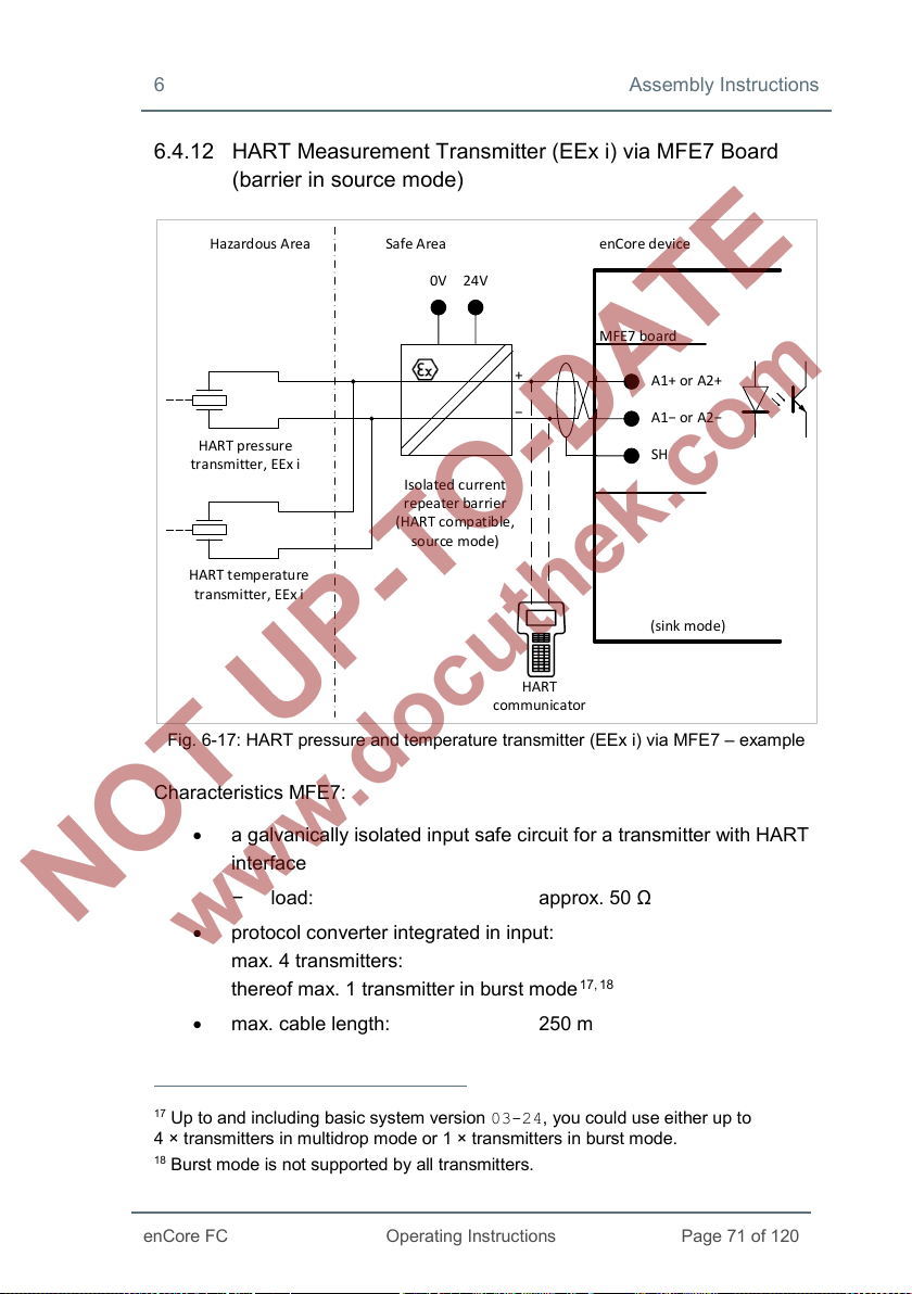
6 Assembly Instructions
enCore FC
Operating Instructions
Page 71 of 120
Ha zardous Area Safe Area enCore device
MFE7 bo ard
A1+ or A2+
A1− or A2−
SH
0V 24V
Isola ted cu rrent
repeater barrier
(HAR T co mpat ible,
so ur ce m od e)
HART pressure
transmitter, EEx i
HART temperature
transmitter, EEx i
HART
comm unicator
+
−
(sink mode)
6.4.12 HART Measurement Transmitter (EEx i) via MFE7 Board (barrier in source mode)
Fig. 6-17: HART pressure and temperature transmitter (EEx i) via MFE7 – example
Characteristics MFE7:
• a galvanically isolated input safe circuit for a transmitter with HART
interface
− load: approx. 50 Ω
• protocol converter integrated in input:
max. 4 transmitters:
thereof max. 1 transmitter in burst mode
• max. cable length: 250 m
17
Up to and including basic system version 03-24, you could use either up to
ransmitters in multidrop mode or 1 × transmitters in burst mode.
4 × t
18
Burst mode is not supported by all transmitters.
17, 18
Page 72
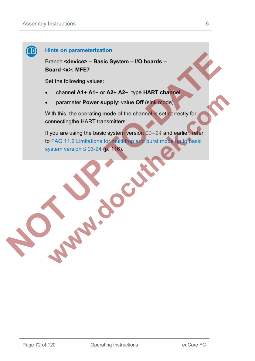
Assembly Instructions 6
Page 72 of 120
Operating Instructions
enCore FC
Hints on parameterization
Branch <device> – Basic System – I/O boards –
Board <x>: MFE7
Set the following values:
• channel A1+ A1− or A2+ A2−: type HART channel
• parameter Power supply: value Off (sink mode)
With this, the operating mode of the channel is set correctly for
connectingthe HART transmitters.
If you are using the basic system version 03-24 and earlier, refer
to FAQ 11.2 Limitations for multidrop and burst mode up to basic
system version ≤ 03-24 (p. 116).
Page 73
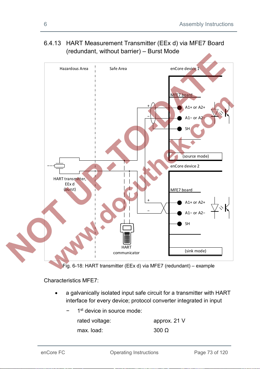
6 Assembly Instructions
enCore FC
Operating Instructions
Page 73 of 120
Ha zardous Area Safe Area enCore device 1
MFE7 bo ard
A1+ or A2+
A1− or A2−
SH
HART transmitter,
EEx d
(burs t)
enCore device 2
MFE7 bo ard
A1+ or A2+
A1− or A2−
SH
HART
comm unicator
+
−
(so ur ce m od e)
(sink mode)
+
−
6.4.13 HART Measurement Transmitter (EEx d) via MFE7 Board (redundant, without barrier) – Burst Mode
Fig. 6-18: HART transmitter (EEx d) via MFE7 (redundant) – example
Characteristics MFE7:
• a galvanically isolated input safe circuit for a transmitter with HART
interface for every device; protocol converter integrated in input
− 1st device in source mode:
rated voltage: approx. 21 V
max. load: 300 Ω
Page 74

Assembly Instructions 6
Page 74 of 120
Operating Instructions
enCore FC
With this, the operating mode of the channel is set correctly for the
− 2nd device in sink mode:
load: approx. 50 Ω
• This operating mode can only be used with one transmitter in burst
mode
19.
• max. cable length: 250 m (total)
Hints on parameterization
Branch <device> – Basic System – I/O boards –
Board <x>: MFE7
Set the following values:
• channel A1+ A1− and A2+ A2−: type HART channel
• each channel with parameter Power supply:
− for device 1: value On (source mode)
− for device 2: value Off (sink mode)
redundant connection of both the HART transmitters with the
ignition protection category EEx d.
19
Burst mode is not supported by all transmitters.
Page 75

6 Assembly Instructions
enCore FC
Operating Instructions
Page 75 of 120
Ha zardous Area Safe Area enCore device 1
MFE7 bo ard
A1+ or A2+
A1− or A2−
SH
HART transmitter,
EEx i
(burs t)
enCore device 2
MFE7 bo ard
A1+ or A2+
A1− or A2−
SH
0V 24V
Isola ted cu rrent
repeater barrier
(HAR T co mpat ible,
so ur ce m od e)
HART
comm unicator
+
−
+
−
(sink mode)
(sink mode)
6.4.14 HART Measurement Transmitter (EEx i) via MFE7 Board (redundant, barrier in source mode) – Burst Mode
Fig. 6-19: HART transmitter (EEx i) via MFE7 (redundant) – example
Characteristics MFE7:
• a galvanically isolated input safe circuit for a transmitter with HART
interface for every device
• both devices in sink mode:
load: approx. 50 Ω
Page 76

Assembly Instructions 6
Page 76 of 120
Operating Instructions
enCore FC
With this, the operating mode of the channel is set correctly for the
• this operating mode can only be used with just one transmitter in
burst mode
20.
• max. cable length: 250 m (total)
Hints on parameterization
Branch <device> – Basic System – I/O boards –
Board <x>: MFE7
Set following values:
• channel A1+ A1− and A2+ A2−: type HART channel
• each channel with parameter Power supply:
− for device 1: value Off (sink mode)
− for device 2: value Off (sink mode)
redundant connection of both the HART transmitters with the
ignition protection category EEx i.
20
Burst mode is not supported by all transmitters.
Page 77

6 Assembly Instructions
enCore FC
Operating Instructions
Page 77 of 120
Ha zardous Area Safe Area enCore device 1
MFE7 bo ard
A1+ or A2+
A1− or A2−
SH
HART pressure
transmitter, EEx d
(multi drop )
enCore device 2
MFE7 bo ard
A1+ or A2+
A1− or A2−
SH
+
−
(so ur ce m od e;
primary master)
(sink mode;
seconda ry master)
+
−
HART temperatur
transmitter, EEx d
(multi drop )
6.4.15 HART Measurement Transmitter (EEx d) via MFE7 Board (Multi-Master, without barrier) – Multidrop Mode (from Basic System 03-25)
Abb. 6-20: HART pressure and temperature transmitter (EEx d)
via MFE7 (primary and secondary master) – example
Characteristics MFE7:
• a galvanically isolated input safe circuit for a transmitter with HART
interface for every device; protocol converter integrated in input
− 1st device in source mode:
Page 78

Assembly Instructions 6
Page 78 of 120
Operating Instructions
enCore FC
rated voltage: approx. 21 V
max. load: 300 Ω
nd
− 2
device in sink mode:
load: approx. 50 Ω
• max. cable length: 250 m (total)
A HART communicator cannot be used in this operating
mode!
Note that for technical reasons it is not possible to use HART
communicator in a HART loop for diagnostic purposes in this
operating mode.
Hints on parameterization
Branch <device> – Basic System – I/O boards –
Board <x>: MFE7
Set the following values:
• channel A1+ A1− and A2+ A2−: type HART channel
• each channel with parameter Power supply:
− for device 1: value On (source mode)
− for device 2: value Off (sink mode)
In folder <channel>: HART loop <x>:
• parameter Master address:
− for device 1: value Primary
− for device 2: value Secondary
• For each transmitter, set the parameter device <x> to used
and parameterize all other settings for the individual
transmitters.
Page 79

6 Assembly Instructions
enCore FC
Operating Instructions
Page 79 of 120
enCore device 1
MFE7 bo ard
A1+ or A2+
A1− or A2−
SH
HART pressure
transm itter, EEx i
(Multi drop)
enCore device 2
MFE7 bo ard
A1+ or A2+
A1− or A2−
SH
0V 24V
Isola ted cu rrent
repeater barrier
(HAR T co mpat ible,
so ur ce m od e)
Ha zardous Area Safe Area
+
−
+
−
(sink mode;
primary master)
(sink mode;
seconda ry master)
HART temperature
transm itter, EEx i
(Multi drop)
6.4.16 HART Measurement Transmitter (EEx i) via MFE7 Board (Multi-Master, barrier in source mode) – Multidrop Mode (from Basic System 03-25)
• a galvanically isolated input safe circuit for a transmitter with HART
• both devices in sink mode:
• max. cable length: 250 m (total)
Abb. 6-21: HART pressure and temperature transmitter (EEx i)
via MFE7 (primary and sekundary master)
interface for every device
load: approx. 50 Ω
Page 80
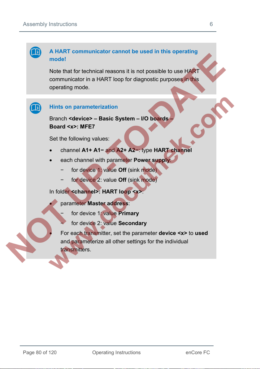
Assembly Instructions 6
Page 80 of 120
Operating Instructions
enCore FC
A HART communicator cannot be used in this operating
mode!
Note that for technical reasons it is not possible to use HART
communicator in a HART loop for diagnostic purposes in this
operating mode.
Hints on parameterization
Branch <device> – Basic System – I/O boards –
Board <x>: MFE7
Set the following values:
• channel A1+ A1− and A2+ A2−: type HART channel
• each channel with parameter Power supply:
− for device 1: value Off (sink mode)
− for device 2: value Off (sink mode)
In folder <channel>: HART loop <x>:
• parameter Master address:
− for device 1: value Primary
− for device 2: value Secondary
• For each transmitter, set the parameter device <x> to used
and parameterize all other settings for the individual
transmitters.
Page 81

6 Assembly Instructions
enCore FC
Operating Instructions
Page 81 of 120
Ha zardous Area Safe Area enCore devic e
Turbi ne:
enco der and
2 LF/HF sensors
Z1+
Z1−
SH
Z2+
Z2−
Z3+
Z3−
12345 67 ,8
ExMFE 5 board
6.4.17 Gas Meter (Turbine): Encoder Index, 2 LF/HF Sensors (EEx i) via ExMFE5 Boards
Fig. 6-22: Interface for turbine meter
encoder index, 2 LF/HF sensors (EEx i) via ExMFE5
Characteristics ExMFE5:
• three intrinsically safe, galvanically isolated input safe circuits of the
category [Ex ib Gb] II C for HF- or LF pulse sensor according to
NAMUR;
active isolated pulse amplifier integrated in the inputs as
“associated electrical equipment” according to EN50020
• Alternatively, one encoder index can be connected with NAMUR
interface on channel 1.
• max. input frequency depending on the operating mode:
− LF: 2 Hz,
− HF: 5 kHz
min. pulse length 200 ms
Page 82

Assembly Instructions 6
Page 82 of 120
Operating Instructions
enCore FC
Hazard ous A rea Safe Area enCore devic e
Turbi ne:
enco der and
2 LF/HF sensors
24V
0V
Isolated pulse
amplifier
(activ e outp ut)
MFE7 bo ard
D1+
SH
D2+
D3+
GND
12345 67 ,8
• max. cable length depending on the operating mode:
− message, LF or encoder: 500 m
− HF (up to 2 kHz): 250 m
− HF (up to 5 kHz): 100 m
6.4.18 Gas Meter (Turbine): Encoder Index, 2 LF/HF Sensors (EEx i) via MFE7 Board
Fig. 6-23: Interface for turbine meter
encoder index, 2 LF/HF sensors (EEx i) via MFE7
Characteristics MFE7:
• three galvanically isolated input safe circuits for HF or LF pulse
sensor
• passive isolated pulse amplifier integrated in the inputs
• Alternatively, one encoder index or a transmitter can be connected
with frequency interface on channel 3.
Page 83
6 Assembly Instructions
enCore FC
Operating Instructions
Page 83 of 120
• max. load: 24 V DC
6 mA
• switching point:
− > 15 V DC: (1)
− < 6.5 V DC: (0)
• max. input frequency depending on the operating mode:
− LF: 8 Hz,
min. pulse length 50 ms
− HF: 5 kHz
− frequency (only channel 3): 5 kHz
(accuracy better than 1 ppm)
• max. cable length depending on the operating mode:
− message, LF or encoder: 500 m
− HF up to 2 kHz: 250 m
− HF up to 5 kHz: 100 m
− frequency: 100 m
Page 84
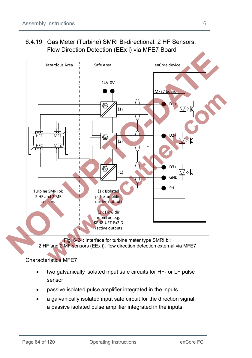
Assembly Instructions 6
Page 84 of 120
Operating Instructions
enCore FC
Hazard ous A rea Safe Area enCore device
MFE7 bo ard
D1+
Turbi ne SMR I bi:
2 HF and 2 MF
sensors
24V
0V
(1): Isola ted
pulse amplifier
(activ e outp ut)
SH
GND
D3+
D2+
MF1
MF2
HF2
HF1
(1)
(2)
(1)
(2): Flow dir
monitor, e.g.
KFU8-UF T-Ex2.D
(activ e outp ut)
6.4.19 Gas Meter (Turbine) SMRI Bi-directional: 2 HF Sensors, Flow Direction Detection (EEx i) via MFE7 Board
Characteristics MFE7:
2 HF and 2 MF sensors (EEx i), flow direction detection external via MFE7
• two galvanically isolated input safe circuits for HF- or LF pulse
Fig. 6-24: Interface for turbine meter type SMRI bi:
sensor
• passive isolated pulse amplifier integrated in the inputs
• a galvanically isolated input safe circuit for the direction signal;
a passive isolated pulse amplifier integrated in the inputs
Page 85

6 Assembly Instructions
enCore FC
Operating Instructions
Page 85 of 120
MFE7 bo ard
D1+
SH
D2+
D3+
GND
24V
0V
Hazard ous A rea Safe Area enCore device
Turbi ne SMR I bi:
2 HF sensor s
Isolated pulse
amplifier
(activ e outp ut)
• max. load: 24 V DC
6 mA
• switching point:
− > 15 V DC: (1)
− < 6.5 V DC: (0)
• max. input frequency in operating mode:
− HF: 5 kHz
• max. cable length depending on the operating mode:
− message: 500 m
− HF (up to 2 kHz): 250 m
− HF (up to 5 kHz): 100 m
6.4.20 Gas Meter (Turbine) SMRI Bi-directional: Flow Direction Detection Internal (EEx i) via MFE7 Board
Fig. 6-25: Interface for turbine meter type SMRI bi:
2 HF sensors (EEx i), flow direction detection internal via MFE7
Page 86
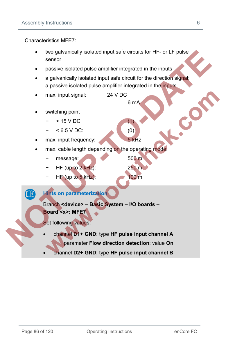
Assembly Instructions 6
Page 86 of 120
Operating Instructions
enCore FC
Characteristics MFE7:
• two galvanically isolated input safe circuits for HF- or LF pulse
sensor
• passive isolated pulse amplifier integrated in the inputs
• a galvanically isolated input safe circuit for the direction signal;
a passive isolated pulse amplifier integrated in the inputs
• max. input signal: 24 V DC
6 mA
• switching point
− > 15 V DC: (1)
− < 6.5 V DC: (0)
• max. input frequency: 5 kHz
• max. cable length depending on the operating mode:
− message: 500 m
− HF (up to 2 kHz): 250 m
− HF (up to 5 kHz): 100 m
Hints on parameterization
Branch <device> – Basic System – I/O boards –
Board <x>: MFE7
Set following values:
• channel D1+ GND: type HF pulse input channel A
− parameter Flow direction detection: value On
• channel D2+ GND: type HF pulse input channel B
Page 87

6 Assembly Instructions
enCore FC
Operating Instructions
Page 87 of 120
Hazard ous A rea Safe Area enCore d evice
MFE7 bo ard
RSA
UFM Q.So nic
(EEx d)
SH
GND
RSB
0V24V
+12/30V DC
Grou nd
Lin e A
Lin e B
0V
24V
RS232C
ser vice
RS485 to RS 232
converter
e.g. ADAM 4520
Data +
Data -
6.4.21 Q.Sonic Ultrasound Gas Meter: Serial RS485 (EEx d) via MFE7 Board
Fig. 6-26: Interface for ultra sound gas meter (Q.Sonic):
serial RS485 (EEx d) via MFE7
Consider the recommendations made with regards to cable length
and connection resistors in refer to chapter 6.4.1 General
Recommendations for Signal and Data Cable (p. 55).
Page 88
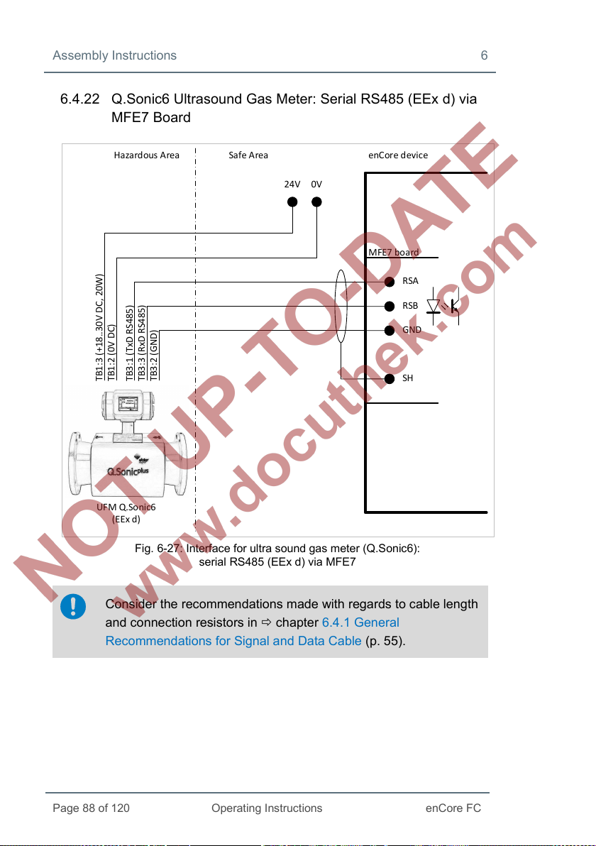
Assembly Instructions 6
Page 88 of 120
Operating Instructions
enCore FC
Ha zardous Area Safe Area
enCore device
MFE7 bo ard
RSA
SH
GND
RSB
0V24V
TB1:3 (+18..30V DC, 20W)
TB1:2 (0V DC)
TB3:1 (TxD RS485)
TB3:3 (RxD RS485)
TB3:2 (GND)
UFM Q.So nic6
(EEx d)
6.4.22 Q.Sonic6 Ultrasound Gas Meter: Serial RS485 (EEx d) via MFE7 Board
Fig. 6-27: Interface for ultra sound gas meter (Q.Sonic6):
serial RS485 (EEx d) via MFE7
Consider the recommendations made with regards to cable length
and connection resistors in chapter 6.4.1 General
Recommendations for Signal and Data Cable (p. 55).
Page 89

6 Assembly Instructions
enCore FC
Operating Instructions
Page 89 of 120
Hazard ous A rea Safe Area
enCore device
MFE7 bo ard
RSA
USM
FLOWSIC600
(EEx d)
RSB
0V24V
1+ (12..24V ±20%)
2-3433
RS232C
ser vice
RS485 to RS 232
converter
e.g. ADAM 4520
0V 24V
Data +
Data -
81
82
RSA
SH
GND
RSB
6.4.23 FLOWSIC600 Ultrasound Gas Meter: Serial RS485 (EEx d) via MFE7 Board
Fig. 6-28: Interface for ultra sound gas meter (FLOWSIC600):
serial RS485 (EEx d) via MFE7
Consider the recommendations made with regards to cable length
and connection resistors in refer to chapter 6.4.1 General
Recommendations for Signal and Data Cable (p. 55).
Page 90

Assembly Instructions 6
Page 90 of 120
Operating Instructions
enCore FC
Hazard ous A rea Safe Area enCore device
COM port RJ45
(CPU or MSER4 bo ard)
6.4.24 Serial Interface through COM Port (CPU or MSER4-Board)
Fig. 6-29: Serial interface through COM port (via CPU or MSER4)
Cable length and the connection resistors
Consider the recommendations made with regards to cable length
and connection resistors in refer to chapter 6.4.1 General
Recommendations for Signal and Data Cable (p. 55).
Hints on parameterization
Branch <device> – Basic System – I/O boards –
Board <x>: MSER4
Select the following values:
• channels CH1/CH2 of the CPU: appropriate Driver mode:
RS232, RS422 or RS485
Page 91

6 Assembly Instructions
enCore FC
Operating Instructions
Page 91 of 120
The following table indicates signal assignment depending on the Driver
mode:
RJ45
Pair no./color RS485 RS422 RS232
Pin no.
1 3/white-orange data A data A TXD
2 3/orange data B data B RTS
3 2/white-green - data A’ RXD
4 1/blue VAUX VAUX VAUX
5 1/white-blue SGND SGND SGND
6 2/green - data B’ CTS
7 4/white-brown VAUX VAUX VAUX
8 4/brown SGND SGND SGND
Table 6: Pin assignment and color coding acc. to standard EIA/TIA 568B21
21
Note that other color coding standards are also usual and commonly used.
Page 92

Assembly Instructions 6
Page 92 of 120
Operating Instructions
enCore FC
Host
enCore device
MFA8 bo ard
SH
I1+
I2+
I3+
I4+
I−
Analog input
boa rd
0/4...20mA
0/4...20mA
0/4...20mA
0/4...20mA
max . 300Ω
max . 300Ω
max . 300Ω
max . 300Ω
6.4.25 Analog Output over MFA8 Board (0/4 ... 20 mA)
Characteristics MFA8:
Fig. 6-30: Analog output via MFA8
• four common galvanically isolated active output safe circuits
(“common ground”) with 0 ... 20 mA- or 4 ... 20 mA interface:
− max. rated voltage: approx. 9 V
− max. permissible load: 300 Ω (in the trough)
• max. measurement error: ±0.1
(in the measuring range 4 ... 20 mA and 0 up to 40 °C ambient
temperature)
• max. cable length: 500 m
% of the measurement
Page 93

6 Assembly Instructions
enCore FC
Operating Instructions
Page 93 of 120
Host enCore device
MFA8 bo ard
SH
D1a
D1b
D2+ or D3+ or D4+
D2− or D3− or D4−
Messa ge input
boa rd
nc,
max . 120 mA
0V
max .
28,8V
Fuse 0,2A
no,
max . 120 mA
Hints on parameterization
Branch <device> – Basic System – I/O boards –
Board <x>: MFA8
Set the following values:
• for the relevant channel I1+ I−, I 2+ I−, I3+ I− or I4+ I−: type
Current output
− parameter Current range: current output range:
0 to 20 mA or 4 to 20 mA
6.4.26 Message Output over MFA8 Board
Fig. 6-31: Message output via MFA8
Page 94

Assembly Instructions 6
Page 94 of 120
Operating Instructions
enCore FC
Characteristics MFA8:
• four galvanically isolated passive output safe circuits for displaying
messages:
− channel D1 interpreted as opener (nc, “normally closed”)
− channel D2, D3 and D4 interpreted as closer (no, “normally
open”)
• max. load per channel: 28.8 V DC
120 mA
• max. cable length: 250 m
Hints on parameterization
Branch <device> – Basic System – I/O boards –
Board <x>: MFA8
Set the following values:
• channel D2+ D2−, D3+ D3− and D4+ D4−: type Message
output
Page 95

6 Assembly Instructions
enCore FC
Operating Instructions
Page 95 of 120
Host
enCore device
MFA8 bo ard
SH
D2+ or D3+ or D4+
D2- or D3- or D4-
Messa ge input
boa rd
max . 120 mA
max . 25 Hz
0V
max .
28,8V
Fuse 0,2A
6.4.27 Pulse Output over MFA8 Board
Fig. 6-32: Pulse output via MFA8
Characteristics MFA8:
• three galvanically isolated passive output safe circuits for displaying
pulses
• max. load per channel: 28.8 V DC
120 mA
• max. pulse rate: 25 Hz
• max. cable length: 250 m
Hints on parameterization
Branch <device> – Basic System – I/O boards –
Board <x>: MFA8
Set the following values:
• channel D2+ D2−, D3+ D3− and D4+ D4−: type Pulse output
Page 96
Page 96 of 120
Operating Instructions
enCore FC
7 Device Configuration and Commissioning
All newly delivered devices are factory-configured so as to support all
available interfaces.
Setting enCore device parameters, i.e. configuring device functions and
adapting the device to the actual measuring point, is done on site using the
enSuite software.
enSuite system requirements and installation
System requirements and details about how to install enSuite are
available in a separate installation guide. The currently valid
version of the file is always located on the enSuite installation CD.
Alternatively you can download the PDF from the Elster Instromet
website from the section Software downloads:
www.elster-instromet.com/en/software-downloads
A gas specialist must be consulted for this procedure. The presence of a
metrology expert is also required when the device is being used within the
scope of legal metrology.
The online help function in enSuite software contains instruc-
tions for operating enSuite as well as a detailed description of its
parameters.
Page 97
7 Device Configuration and Commissioning
enCore FC
Operating Instructions
Page 97 of 120
7.1 Device Configuration
This section gives brief instructions on how to create a complete confi-
guration for enCore devices and how to transfer the configuration into the
device on-site via USB. For details refer to volume ”Configuration of
Device Software” of the enCore FC manual.
Opening the security switch
As a general rule, there are parameters which cannot be
changed, if the security switch is closed – especially if the device
is used within the scope of legal metrology. If a new
parameterization refers to such a parameter, then the security
switch must be opened, such that the presence of a metrology
expert may be required in some instances.
The following steps are required:
► Start enSuite on your computer.
► Establish the USB connection with your enCore device.
► Use enSuite to create a suitable device parameterization.
► Open the security switch if required.
► Transfer the parameterization to the device.
As soon as the transfer of the parameterization begins, a login dialog
appears on the computer screen.
► Login as an administrator.
Standard login
A standard login as an administrator (user name admin1 and an
empty password) typically works here if you have not changed the
start-up settings for user administration. Otherwise follow the
individual user configuration of the device.
After a successful login the data transfer begins.
Page 98
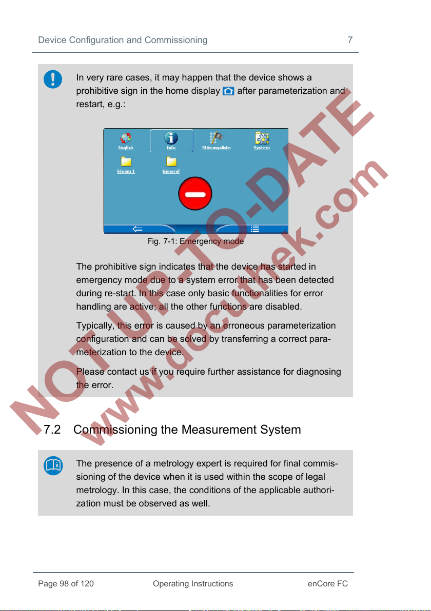
Device Configuration and Commissioning 7
Page 98 of 120
Operating Instructions
enCore FC
In very rare cases, it may happen that the device shows a
prohibitive sign in the home display after parameterization and
restart, e.g.:
Fig. 7-1: Emergency mode
The prohibitive sign indicates that the device has started in
emergency mode due to a system error that has been detected
during re-start. In this case only basic functionalities for error
handling are active; all the other functions are disabled.
Typically, this error is caused by an erroneous parameterization
configuration and can be solved by transferring a correct para-
meterization to the device.
Please contact us if you require further assistance for diagnosing
the error.
7.2 Commissioning the Measurement System
The presence of a metrology expert is required for final commis-
sioning of the device when it is used within the scope of legal
metrology. In this case, the conditions of the applicable authori-
zation must be observed as well.
Page 99
7 Device Configuration and Commissioning
enCore FC
Operating Instructions
Page 99 of 120
7.2.1 Checking Device Settings
The legally relevant parameters can be checked in special device displays
( volume “Use in Legal Metrology” of the enCore FC manual). The enSuite
software will allow you to carry out a complete check of the current device
parametrization when the software has an online connection to the device.
7.2.2 Checking Measurement Input Values
Input measurements, in particular input values for flow conversion
(measurement data from gas meters, pressure transmitters, temperature
transmitters and, if applicable, gas composition measurement devices) can
be checked on the device display ( volume “Use in Legal Metrology” of the
enCore FC manual).
7.2.3 Checking Output Signals
Parameterized output signals can be measured using appropriate measure-
ment devices and checked in that way.
7.2.4 Checking Digital Communication (Modbus, etc.)
Appropriate tools (e.g. a protocol analyzer) can be used to check digital
communication.
7.2.5 Checking Measurements and Calculations
A final check of the accuracy of measurement results and calculations must
be executed when the device is used within the scope of legal metrology. A
metrology expert is required for this process, and the applicable legal regu-
lations must be observed.
7.2.6 End of Commissioning (from Basic System 03-24)
enSuite provides a convenient function to prepare an enCore flow computer
for operation at the end of commissioning. This function combines different
actions (e.g. the action Erase fiscal audit trail or Set counters) per stream.
Page 100

Device Configuration and Commissioning 7
Page 100 of 120
Operating Instructions
enCore FC
This function is available in normal mode during online parametrization only.
Requirement is that the calibration switch is open. Depending on the action
you want to execute, you need the user right Erase fiscal audit trail/fiscal
archives and/or the rights for the individual counters on parameter level.
Call:
<Stream 1/Stream 2>, tab End of commissioning
7.2.7 Sealing (if necessary)
It may be necessary for the device as well as sensor and signal lines to be
sealed by a metrology expert when it is used within the scope of legal metro-
logy. The conditions of the applicable authorization must be observed in this
case.
 Loading...