

Page 1
Smile SDC heating and
district heating controller
SERVICE MANUAL
EN2H-0221GE51 R0808
Page 2

EN2H-0221GE51 R0808
Page 3

SDC / DHC Contents
Contents
1 Software version ..........................................................................................................11
2 Safety instructions.......................................................................................................11
2.1 Intended use .....................................................................................................11
2.2 Requirements for start-up..................................................................................11
2.2.1 Power supply ........................................................................................12
2.2.2 Connection conditions ..........................................................................12
2.2.3 Cable cross-sections ............................................................................12
2.2.4 Maximum cable lengths........................................................................12
2.2.5 Cable installation ..................................................................................12
2.2.6 Grounding and zeroing .........................................................................13
2.3 Hot-water temperature greater than 60 °C ........................................................13
2.4 Connection of accessory parts ..........................................................................14
2.5 Maintenance and cleaning ................................................................................14
2.6 Safety precautions for EMC-compliant installation ............................................15
3 Overview.......................................................................................................................20
4 Abbreviations ...............................................................................................................21
5 Operation......................................................................................................................22
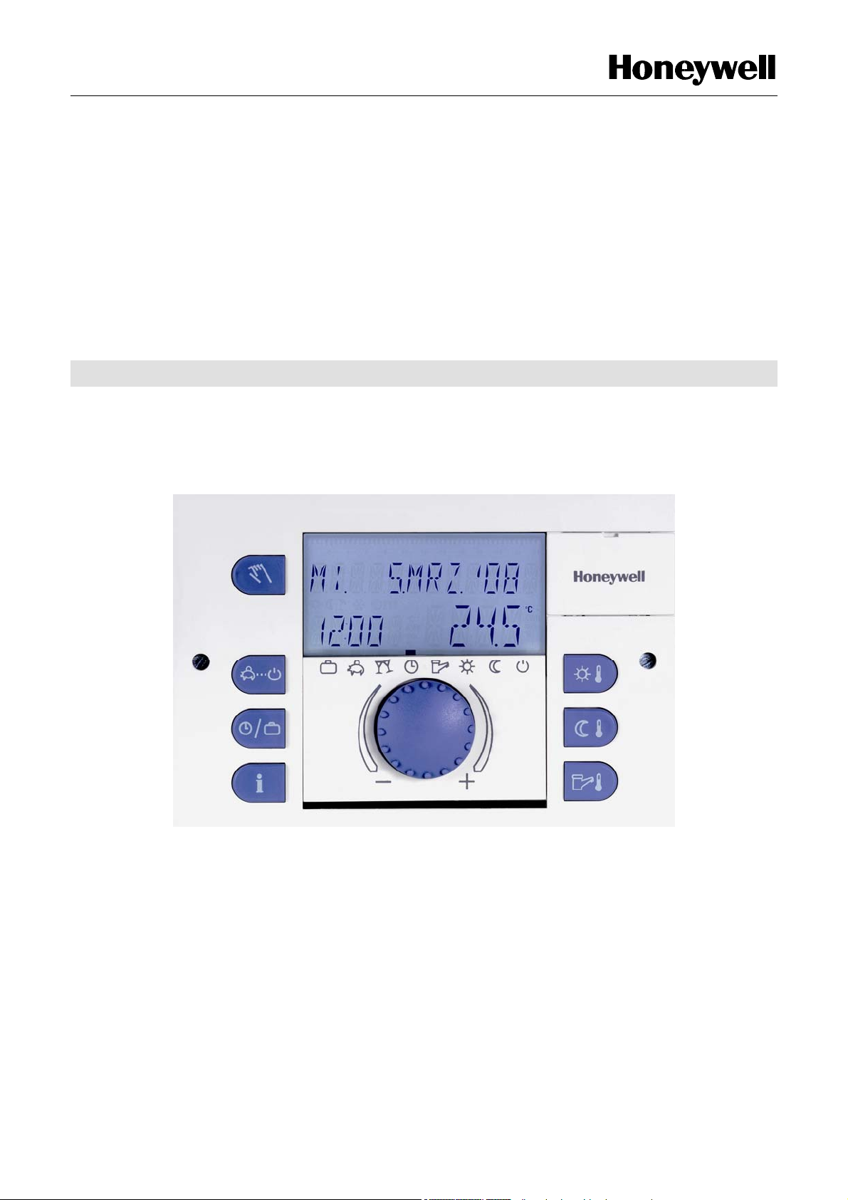
5.1 Display and operating elements ........................................................................22
5.1.1 Display (basic display)..........................................................................23
5.1.2 Operating elements ..............................................................................24
5.1.2.1 Input button (press / turn)........................................................24
5.1.2.2 "Daytime room temperature" button ........................................24
5.1.2.3 "Night-time room temperature" button.....................................25
5.1.2.4 "Daytime hot-water temperature" button .................................25
5.1.2.5 "Operating mode" button (basic display) .................................26
5.1.2.6 "Switching time programs / Holiday programs" button ............33
5.1.2.7 "System information" button....................................................35
5.1.2.8 "Manual mode" / "Emission measurement" button ..................44
EN2H-0221GE51 R0808 3
Page 4

Contents SDC / DHC
5.1.2.9 Access to the technician / OEM area ......................................46
5.1.2.10 Heating curve..........................................................................47
5.2 Menu-selection level..........................................................................................48
5.2.1 "Time - Date" menu ..............................................................................54
5.2.2 "Timeprograms" menu ..........................................................................55
5.2.2.1 Selection of the control circuit .................................................56
5.2.2.2 Selection of the program .........................................................56
5.2.2.3 Selection of day of the week and cycle ...................................56
5.2.2.4 Programming switching times and cycle temperatures ...........57
5.2.3 "System Parameters" menu..................................................................72
5.2.3.1 Language selection .................................................................72
5.2.3.2 Time program..........................................................................73
5.2.3.3 Operating mode ......................................................................74
5.2.3.4 Parameter reset ......................................................................76
5.2.3.5 Complete reset........................................................................77
5.2.4 "DHW" menu ........................................................................................77
5.2.4.1 Night-time hot-water temperature............................................78
5.2.4.2 Legionella protection day ........................................................78
5.2.5 "Direct Heating Circuit" / "Mixed Heating Circuit 1" / "Mixed
Heating Circuit 2" menu........................................................................78
5.2.5.1 Reduced operation..................................................................79
5.2.5.2 Heating system .......................................................................80
5.3 Error messages.................................................................................................80
5.4 Parameter settings ............................................................................................81
5.4.1 "Hydraulics" menu (HYDRAULIC) ........................................................81
5.4.2 "System parameters" menu (SYSTEM)................................................85
5.4.3 "Hot-water circuit" menu (DHW) ...........................................................89
5.4.4 "Direct heating circuit" menu (UNMIXED CIRC) ...................................92
5.4.5 "Mixed heating circuit 1 / 2" (MIX.VALVE - 1 / MIX.VALVE - 2)
menus ...................................................................................................95
5.4.6 "Heat generator" menu (HEAT GENER................................................99
4 EN2H-0221GE51 R0808
Page 5

SDC / DHC Contents
5.4.7 "District hot water" menu (DIST.HEATING) ........................................104
5.4.8 "Return increase" menu (RETURN CONTR)......................................105
5.4.9 "Solar" menu (SOLAR) .......................................................................106
5.4.10 "Solid" menu (SOLID FUEL) ...............................................................107
5.4.11 "Buffer" menu (BUFFER)....................................................................108
5.4.12 "Total flow regulation" menu (MAIN SUPPLY)....................................109
5.4.13 "Cascading" menu (CASCADE) .........................................................110
5.4.14 "Data bus" menu (BUS) ......................................................................111
5.4.15 "Relay test" menu (RELAY TEST ) ....................................................111
5.4.16 "Error messages" menu (ALARM) ......................................................112
5.4.17 "Error messages 2" menu (ALARM 2) ................................................113
5.4.18 "Sensor calibration" menu (SENSOR ADJ.) .......................................113
6 Control Functions ......................................................................................................114
6.1 Variable adjustment of the hydraulic parameters (variable inputs and
outputs) ...........................................................................................................114
6.1.1 Connection and settings table ............................................................116
6.2 Switching time program enabling ....................................................................117
6.3 Suppressing the cycle temperature on time program level..............................118
6.4 Enabling "Separate Control Mode"..................................................................118
6.5 Switching from SDC to DHC ...........................................................................119
6.6 Selection of hydraulic parameter presettings ..................................................119
6.7 The variable inputs and outputs of device series SDC/DHC 43 ......................119
6.8 General functions and their operation .............................................................120
6.8.1 Outside temperature sensing..............................................................120
6.8.1.1 Building type .........................................................................120
6.8.2 Heating circuit outside temperature assignment.................................121
6.8.3 Outside temperature emergency operation value...............................121
6.8.4 Outside temperature disable...............................................................122
6.8.5 Climate zone.......................................................................................122
6.8.6 Design temperature ............................................................................122
6.8.7 Summer switch-off..............................................................................123
EN2H-0221GE51 R0808 5
Page 6

Contents SDC / DHC
6.8.8 System frost protection.......................................................................124
6.8.9 Pump forced operation .......................................................................127
7 Hydraulic Components..............................................................................................128
7.1 Heat generator: Boiler .....................................................................................128
7.1.1 Heat generator start-up protection......................................................128
7.1.2 Heat generator minimum temperature limit.........................................129
7.1.3 Maximum temperature limit heat generator ........................................130
7.1.4 Heating circuits minimum temperature limit ........................................130
7.1.5 Heat generator sensor control mode ..................................................130
7.1.6 Minimum burner runtime.....................................................................131
7.1.7 Switching: Multi-stage heat generator/Switching differential...............131
7.1.8 Operation for modulating burners .......................................................136
7.1.9 Modulation of P part (Xp)....................................................................137
7.1.10 Modulation of sample time Ta.............................................................137
7.1.11 Modulation of integral action time Tn ..................................................138
7.1.12 Modulation of runtime .........................................................................138
7.1.13 Modulation of start time ......................................................................138
7.1.14 Modulation of start power ...................................................................139
7.1.15 OpenTherm ........................................................................................140
7.1.16 Use of boiler sensor 2.........................................................................141
7.1.17 External heat generator cut-off ...........................................................141
7.1.18 Heat generator forced discharge ........................................................141
7.1.19 Exhaust gas temperature monitoring ..................................................142
7.1.20 Burner counter mode ..........................................................................143
7.2 Heat generation, heat exchanger, district heating ...........................................144
7.2.1 On/Off operation of the district heating valve......................................145
7.2.2 Continuous heat exchanger valve control...........................................145
7.2.3 District heating return temperature limit..............................................147
7.2.4 Return temperature limit for hot-water loading....................................149
7.2.5 Hot-water pre-regulator with district heating systems .........................150
7.2.6 Mode of operation: Hot-water pre-control ...........................................151
6 EN2H-0221GE51 R0808
Page 7

SDC / DHC Contents
7.2.7 Quick hot-water control.......................................................................152
7.2.8 Mode of operation of hot-water control mode "external
operation" ...........................................................................................154
7.2.9 Conditional parallel operation for mixed heating circuits.....................155
7.2.10 Circulation pump control mode ...........................................................155
7.2.11 Switch-off of district heating control ....................................................156
7.2.12 Return interval flushing .......................................................................156
7.2.13 Heat meter for additional limitation according to the volume flow
or thermal output ................................................................................156
7.2.14 Charging pump (CHP) ........................................................................157
7.2.15 Primary pump .....................................................................................158
7.2.16 Boiler circuit pump ..............................................................................158
7.2.17 Return increase ..................................................................................159
7.2.17.1 Bypass pump (RBP)..............................................................160
7.2.17.2 Return maintenance through controlled feed water
addition 160
7.2.17.3 Indirect return increase .........................................................161
7.3 Heating circuit .................................................................................................161
7.3.1 General heating circuit functions ........................................................161
7.3.1.1 Heating curve........................................................................161
7.3.1.2
7.3.1.3 Reduced operation................................................................164
7.3.1.4 Heating system .....................................................................164
7.3.1.5 Heating circuit temperature limit............................................164
7.3.1.6 Heating circuit temperature offset .........................................165
7.3.1.7 Heating circuit pump extended running time .........................165
Heating curve setting (heating curve)....................................162
7.3.1.8 Screed function .....................................................................165
7.3.2 Heating circuit constant temperature control ......................................168
7.3.3 Fixed-value control .............................................................................168
7.3.4 Consideration of the room temperature/room influence......................169
7.3.4.1 Heating circuit room connection............................................169
7.3.4.2 Heating circuit room factor ....................................................170
EN2H-0221GE51 R0808 7
Page 8

Contents SDC / DHC
7.3.4.3 Heating circuit room controller ..............................................171
7.3.4.4 Switch-on/switch-off optimisation ..........................................171
7.3.4.5 Room setpoint ramp..............................................................175
7.3.4.6 Heating limit function.............................................................175
7.3.4.7 Heating circuit room frost protection limit ..............................177
7.3.4.8 Mixed heating circuits cooling switch-over ............................177
7.3.4.9 Heating circuit name .............................................................180
7.3.4.10 Room thermostat function (maximum room
temperature limit) ..................................................................181
7.3.5 Hot-water production ..........................................................................187
7.3.5.1 Hot-water tank loading (SLP) ................................................187
7.3.5.2 Circulation pump (CIR.).........................................................194
7.3.6 Solar/Solid fuel/Buffer.........................................................................196
7.3.6.1 Solar function ........................................................................196
7.3.6.2 Buffer tank function ...............................................................199
7.3.6.3 Solid fuel function..................................................................212
7.3.7 Tank loading switch-over....................................................................213
7.3.8 Hydraulic buffer relief (HBR)...............................................................215
Easy enabling and disabling of a heating pump .................................216
7.3.9
7.3.10 Other system components..................................................................217
7.3.10.1 Global fault message input....................................................217
7.3.10.2 Global fault message output .................................................217
7.3.10.3 Timer 217
7.3.10.4 External switching modem ....................................................218
7.3.10.5 External information ..............................................................219
7.3.10.6 Demand contact....................................................................219
7.3.11 Bus communication ............................................................................221
7.3.11.1 Bus address of central device ...............................................221
7.3.11.2 Control functions via the data bus.........................................222
7.3.11.3 Operation of wall devices ......................................................227
7.3.12 Cascading of heat generators in the bus system................................232
8 EN2H-0221GE51 R0808
Page 9

SDC / DHC Contents
7.3.12.1 General description of cascading of control devices .............232
7.3.12.2 Function of the cascade parameters.....................................233
7.3.12.3 Mode of operation of cascade control ...................................234
7.3.13 Commissioning, maintenance and troubleshooting help ....................237
7.3.13.1 Automatic set function...........................................................237
7.3.13.2 Emission measurement (not for DHC 43) .............................238
7.3.13.3 Relay/function test.................................................................239
7.4 Error messages...............................................................................................243
7.4.1 Basic display/fault stack fault messages ............................................248
7.4.1.1 Sensor calibration .................................................................249
7.4.1.2 Full controller reset................................................................249
7.4.1.3 Controller time correction ......................................................249
8 Technical data............................................................................................................250
8.1 General ...........................................................................................................250
8.1.1 Installation recommendations .............................................................251
8.2 Sensor resistance values ................................................................................251
8.2.1 NTC 20 ...............................................................................................251
8.2.2 PT 1000 ..............................................................................................252
8.3 Sensor measurement ranges ..........................................................................252
8.4 Digital inputs....................................................................................................253
9 Log ..............................................................................................................................254
Index....................................................................................................................................255
EN2H-0221GE51 R0808 9
Page 10

Contents SDC / DHC
10 EN2H-0221GE51 R0808
Page 11

SDC / DHC Software version
1 Software version
This documentation is valid for software version V 3.0 of your
control device. The software version is displayed after switch-on
for approx. 8 s. If you are using an older software version, please
contact your heating technician.
2 Safety instructions
2.1 Intended use
The SDC / DHC Smile family of controllers was designed for the
sole purpose of regulating and controlling hot-water, heating and
district heating systems (including hot-water production) that do
not exceed a maximum flow temperature of 120 °C.
2.2 Requirements for start-up
ATTENTION
The heating system must be complete and filled with water
so that the pumps do not run dry and the heating boiler is not
damaged.
The control equipment must be installed in accordance with
the installation instructions.
All electrical connections (voltage supply, burner, mixer
motor, pumps, sensor wiring etc.) must be carried out by the
technician in accordance with the applicable VDE regulations
and correspond with the circuit diagrams.
If floor heating is connected, a limiting thermostat must also
be installed in the flow line after the heating circuit pump.
This switches off the pumps at excessive flow temperatures.
Before starting up the controller, have the heating technician
check all requirements listed above.
NOTE
The current time and date are already set at the factory and are
backed up by a battery.
The time switch functions based on a basic program and the
control functions are preset for common heating systems with lowtemperature boilers.
EN2H-0221GE51 R0808 11
Page 12

Safety instructions SDC / DHC
2.2.1 Power supply
Do not disconnect the controller from the mains supply!
The battery for saving all individualised data is otherwise
unnecessarily strained. The frost-protection function of the
controller is deactivated.
2.2.2 Connection conditions
All electrical connection work may only be carried out by qualified
personnel!
2.2.3 Cable cross-sections
1.5 mm2 for all cables carrying 230 V (power supply, burner,
pumps, actuator).
0.6 mm2 for bus cables (recommended type J-Y(St)Y 2 x 0.6).
0.5 mm2 for sensors, selectors and analog signal cables.
2.2.4 Maximum cable lengths
Sensor, selector and analog inputs
We recommend using cables no longer than 200 m. Longer
connection lines could be used, but increase the risk of
interference.
Relay outputs
Unlimited cable length.
Bus connections
Max. length of 100 m from the first bus subscriber to the last one
(incl. wall modules).
2.2.5 Cable installation
Install cables for sensors apart from the cables carrying 230 V!
Branch boxes in the sensor cable must be avoided!
12 EN2H-0221GE51 R0808
Page 13

SDC / DHC Safety instructions
2.2.6 Grounding and zeroing
Local regulations on the connection of equipment must be
observed!
2.3 Hot-water temperature greater than 60 °C
ATTENTION
Note that there is a danger of scalding at all hot-water drawoff points (kitchen, bathroom etc.) in the following cases.
Add sufficient cold water in these cases.
Automatic anti-
legionella mechanism
When the automatic anti-legionella mechanism is activated, the
hot water is automatically heated to the anti-legionella
temperature (65 °C at the factory) on the selected day and at the
selected time to kill any legionella bacteria found in the hot-water
tank.
Manual mode /
Emission
measurement
In the manual mode / emission measurement operating mode, the
hot water is heated up to the highest possible boiler temperature,
as the burner and all pumps are switched on and the mixer is
opened fully. There is an acute danger of scalding at all
connected hot-water draw-off points! Add sufficient cold water or
switch off the hot-water loading pump (at the switch of the pump,
if present). Heating and hot water are in unregulated continuous
operation. This operating mode is for special use by the chimney
sweep for emission measurement or if the controller is defective.
The high hot-water temperatures can be prevented, however, by
setting the boiler thermostat to a max. boiler temperature of
approx. 60 °C.
EN2H-0221GE51 R0808 13
Page 14

Safety instructions SDC / DHC
2.4 Connection of accessory parts
WARNING
According to VDE 0730, a separator for each mains terminal
is to be provided in the voltage supply to the control
equipment. Observe the local regulations regarding
grounding and zeroing.
As soon as the mains voltage is applied to terminals 21, 22,
2, 6, 12 and 18, headers X3 and X4 can also carry mains
voltage.
If the heating circuit and hot-water loading pumps do not
have an On / Off switch, but manual switch-on and switch-off
capability is still desired, the appropriate switches must be
installed by the customer. All accessory parts (sensors,
selectors etc.) are to be connected to the respective circuit
diagram.
2.5 Maintenance and cleaning
The controller is maintenance-free. The device can be cleaned
externally with a moist (not wet) cloth.
14 EN2H-0221GE51 R0808
Page 15
SDC / DHC Safety instructions
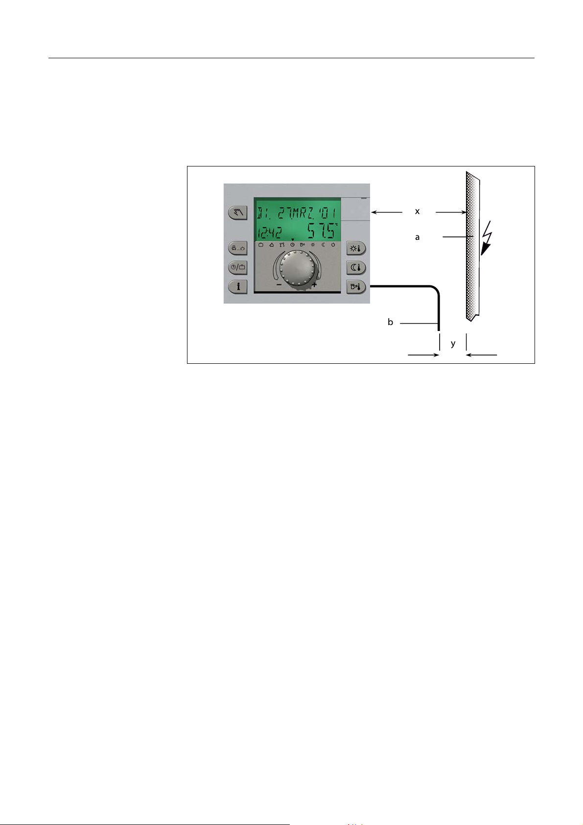
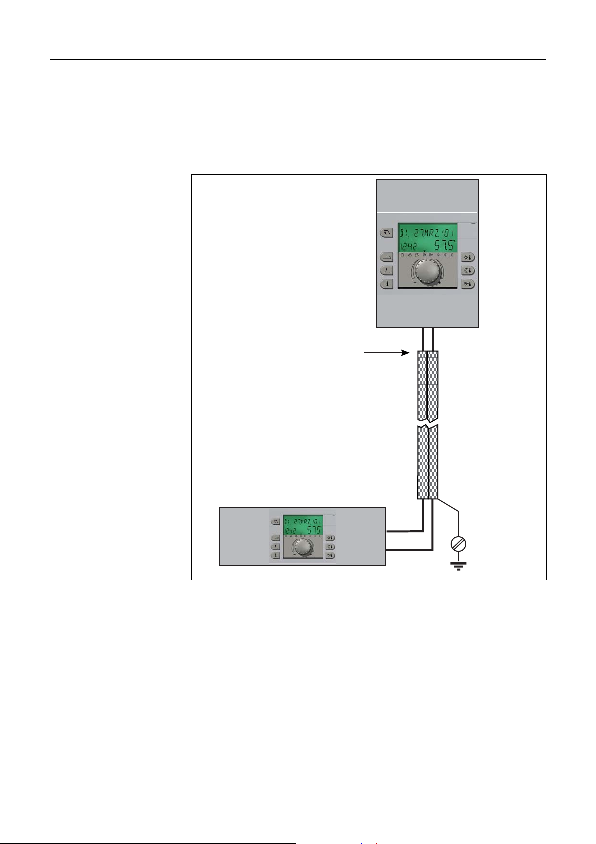
2.6 Safety precautions for EMC-compliant installation
Mains lines and sensor/data bus lines must be installed separate
from each other. A minimum of 2 cm space must be present
between the lines. It is permissible to cross lines.
x
a
ç
é
æ
b
y
a Mains 230 V AC x 15 cm
b Data bus line 12 V AC y 2 cm
For control devices with their own mains connection, separate
installation of mains and sensor/bus lines must absolutely be
ensured. If cable ducts are used, they are to be provided with cutoff bridges.
EN2H-0221GE51 R0808 15
Page 16
Safety instructions SDC / DHC
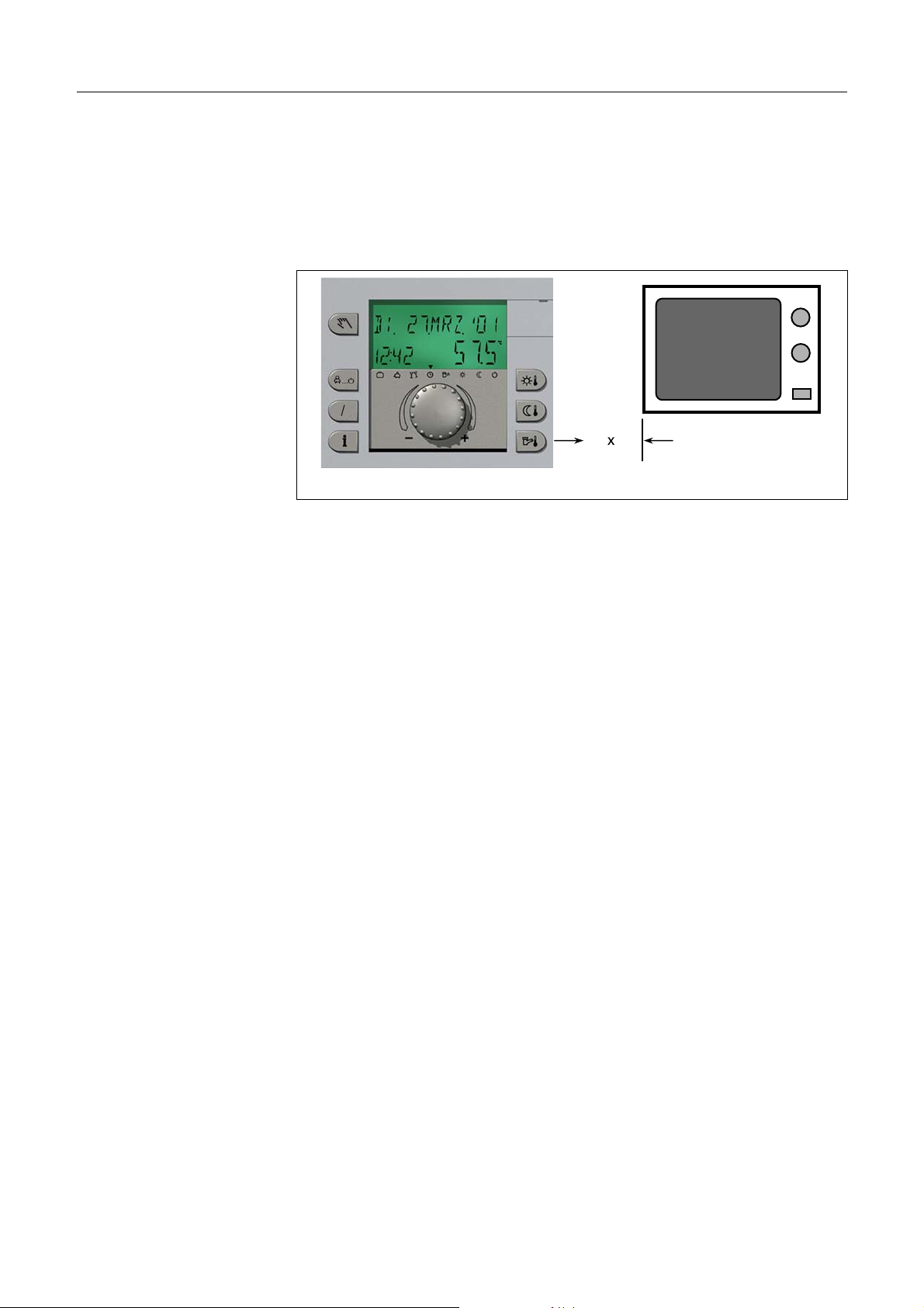
When installing control or wall devices, a minimum spacing of
40 cm to other electrical equipment with electromagnetic
emissions, e.g. relays, motors, transformers, dimmers, microwave
ovens and televisions, audio speakers, computers, cordless
telephones etc., is to be ensured.
ç
é
æ
x
x 40 cm
A minimum spacing of 40 cm is to be ensured between wall
devices and central devices. Multiple central devices in the data
bus system can be mounted directly next to one another.
16 EN2H-0221GE51 R0808
Page 17
SDC / DHC Safety instructions
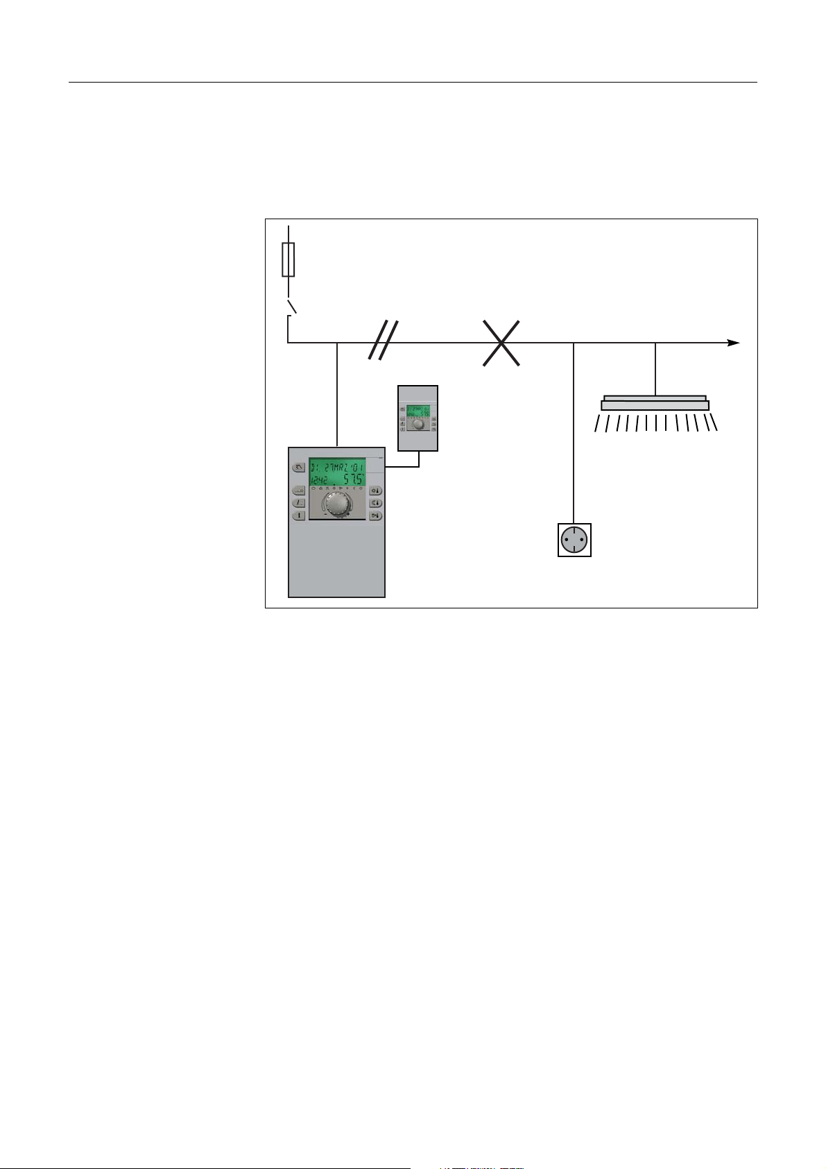
The mains connection of the heating system (boiler – panel –
control equipment) must be designed as a separate circuit.
Neither fluorescent lamps nor any machines which are potential
sources of interference may be connected/connectable.
a
c
b
ç
é
æ
ç
é
æ
d
e
a Safety fuse 16 A
b Boiler room emergency switch
c Connect boiler room lighting and electrical outlets to
separate circuits only!
d Wall devices
e Heat generator
Shielded cables must be used for the data bus lines.
For a recommended layout, see 8 Technical data, pg. 250
EN2H-0221GE51 R0808 17
Page 18
Safety instructions SDC / DHC
The earth connection of the cable shielding must occur on one
side at the protective conductor connection, e.g. at the cladding
plate of the heat generator, protective conductor terminal etc.
Multiple earth connections of a single cable are not permissible
(buzzing loop).
ç
é
æ
a
b
ç
é
æ
PE
a No earth connection here! b Central device
18 EN2H-0221GE51 R0808
Page 19
SDC / DHC Safety instructions
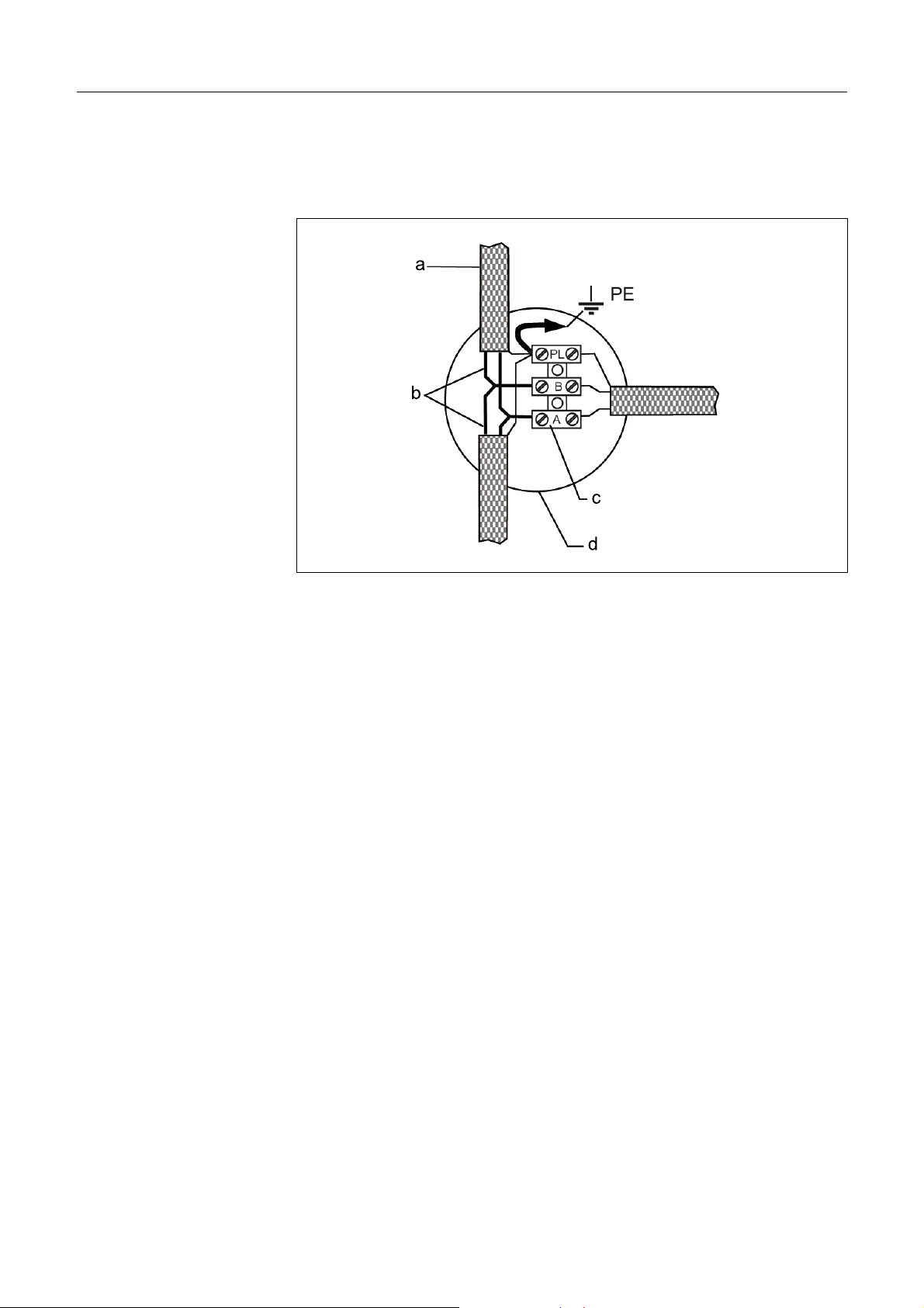
With star-topology data bus systems, double earth connections
may not be made. The earth connection must be made on one
side of the star!
a Shielding b Two-lead data bus line
c Distributor terminal d Branch box
The outside sensor may not be installed near transmitters or
receivers (e.g. on garage walls near garage door opener
receivers, amateur radio antennas, radio alarm systems or directly
next to large transmission equipment etc.).
EN2H-0221GE51 R0808 19
Page 20
Overview SDC / DHC
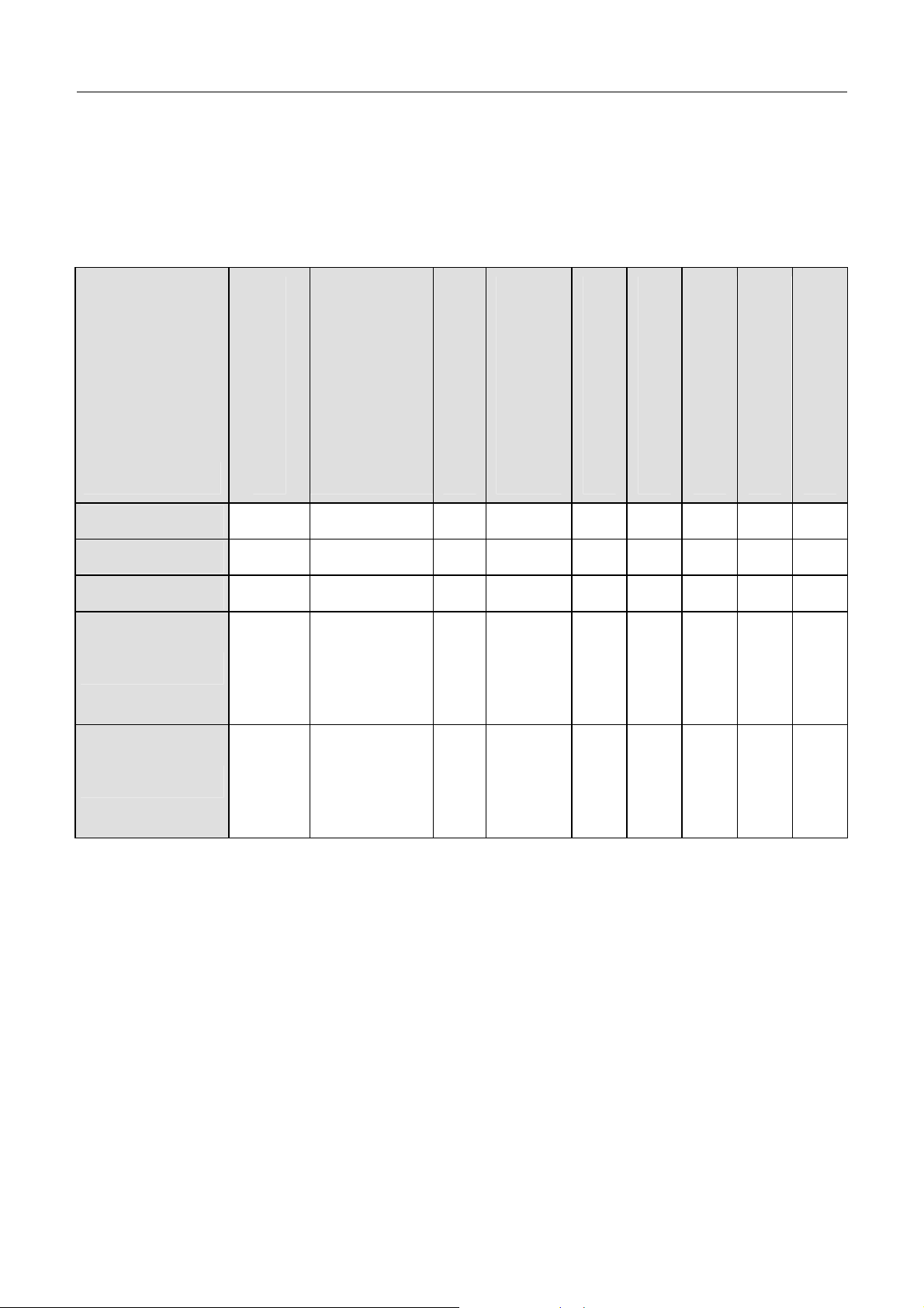
3 Overview
The modular SDC / DHC control device is available in an
installable switch cabinet version and a surface-mounted wall
version with the following equipment features:
Type
SDC 3-10
SDC 3-40
SDC 7-21 1)
SDC 9-21 2)
SDC 12-31 3)
Number of output relays
Burner stage 2
or
District heating valve
CLOSED
Burner stage 1
Direct heating circuit
Variable output 3
Mixed heating circuit 1
Mixed heating circuit 2
Tank loading pump
Variable output 2
3 – x x – – x –
3 – – – x – – – –
7 – x x x – x – –
7
x x x x – x x x
+ two
variable
relays
10
x x x x x x x x
+ two
variable
relays
1)
DHC 43-1
2)
DHC 43-2
3)
DHC 43-3
Variable output 1
20 EN2H-0221GE51 R0808
Page 21

SDC / DHC Abbreviations
4 Abbreviations
The following abbreviations are used in this documentation/in the
display of the control device:
RED
OS
OS2
FGS
OT
BUS
OC1
OC2
DC
DCP
ECO
EHR
SFB
SFR
FC
Lowering operation
Outside sensor
Outside sensor 2
Flue gas sensor
Outside temperature
System data bus
Burner stage 1 operating hour
counter
Burner stage 2 operating hour
counter
Direct heating circuit
Direct heating circuit pump
Switch-off operation
Electric heating rod
Solid fuel boiler sensor
Solid fuel buffer sensor
Fixed-value control
BS 2
BLP
RBP
RP
SD I
SD II
TS
TLP
SLS
SLSS
SFD
SLP
STL
VO
VO1
Buffer sensor 2 (bottom)
Buffer loading pump
Return bypass pump
Return pump
Switching differential I
Switching differential II
Tank sensor
Tank loading pump
Solar loading switch-over
Solar loading switch-over sensor
Solar forced dissipation
Solar loading pump
Stratified tank loading pump
Variable output (general)
Variable output 1
SFP
PI
BP
CC
CRS
CTBS
CFS
MM
MC
MHP
P1
P2
P3
BS
Solid fuel pump
Pulse input
Boiler circuit pump
Constant control
Collector return sensor
Collector tank/buffer sensor
Collector flow sensor
Mixer motor
Mixed heating circuit
Mixed heating circuit pump
Switching time program
Switching time program
Switching time program
Buffer sensor (top)
VO2
VI
VI1
VI2
VI3
FM1
FM2
PHE
HG
HGS
WD
HW
CIR
CHP
Variable output 2
Variable input (general)
Variable input 1
Variable input 2
Variable input 3
Flow sensor of mixed heating
circuit 1
Flow sensor of mixed heating
circuit 2
Parallel heat generator enable
Heat generator
Heat generator sensor
Wall device for room temperature
sensing
Hot water
Circulation pump
Charging pump
EN2H-0221GE51 R0808 21
Page 22
Operation SDC / DHC
5 Operation
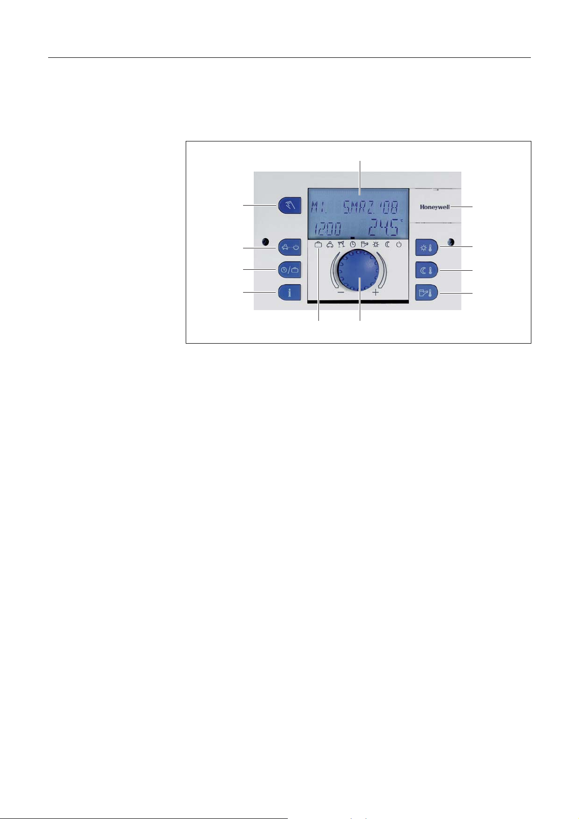
5.1 Display and operating elements
5
1
2
3
4
1011
6
7
8
9
1 "Manual mode" / "Emission measurement" button (not on
district heating controllers)
2 "Operating modes" button (basic display)
3 "Switching time programs" / "Holiday programs" button
4 "System information" button
5 Display
6 Cover clip for service socket
7 "Daytime room temperature" button
8 "Night-time room temperature" button
9 "Daytime hot-water temperature" button
10 Input button (press / turn)
11 Operating mode symbols (heating programs)
22 EN2H-0221GE51 R0808
Page 23
SDC / DHC Operation
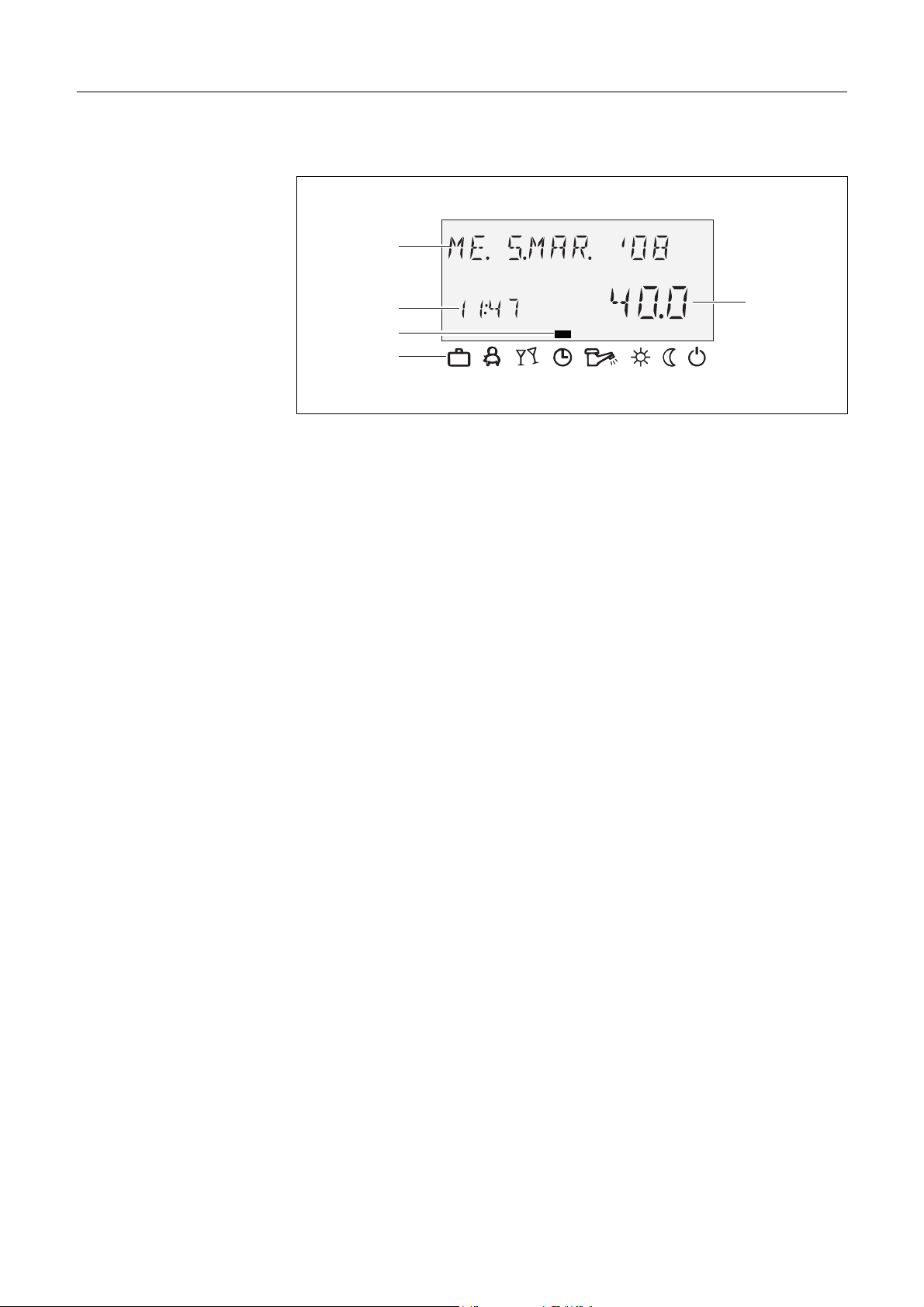
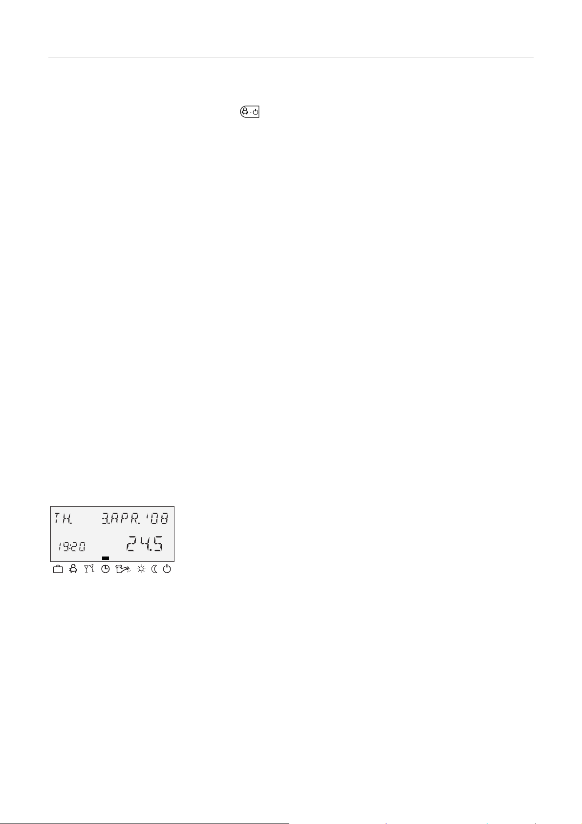
5.1.1 Display (basic display)
1
C
2
5
3
4
1 Day of the week / Date 4 Operating mode symbols
2 Time 5 Heat generator temperature
3 Active operating mode
The illumination of the display is switched on by pressing any
button or using the input button î and switches off automatically
if no buttons are pressed for a longer period of time.
During start-up of the unit and after a power failure, a segment
test with automatic fault diagnosis is carried out. The respective
device type and the software version number then appear briefly.
The basic display that then appears shows the day of the week,
the date, the time and the heat generator temperature in
automatic mode. Different values appear in the basic display
depending on the set operating mode (AUTOMATIC, PARTY
etc.). Thus, for example, in the ABSENT operating mode, the
indication ABSENT TIL appears instead of the date and the return
date instead of the temperature. Active summer deactivation is
indicated by a beach umbrella symbol
protection is indicated by a snowflake symbol
À, and active frost
Á.
EN2H-0221GE51 R0808 23
Page 24

Operation SDC / DHC
5.1.2 Operating elements
5.1.2.1 Input button (press / turn)
By pressing once, you can:
ð
• Confirm input / values
By pressing and holding (approx. 3 s), you can:
• Switch to the menu-selection level
• Move up one menu level
By turning the input button î, you can:
• Change values (clockwise increases called-up values,
anticlockwise decreases them)
• Navigate through menus
5.1.2.2 "Daytime room temperature" button
Sets the desired room temperature (room setpoint) in automatic
¥
mode during the heating cycles and in the PARTY and HEATING
operating modes. In operating mode 1, the set value for all
heating circuits is the same. In operating mode 2, the set value
applies for the respective heating circuit. To set the operating
mode, see 5.2.3.3 Operating mode, pg. 74.
Setting
► Press ¥ button.
► Set flashing room temperature specification to the desired
C
value by turning the input button î.
► Confirm set value by pressing the
button î.
¥ button or the input
Alternative: Automatic acceptance of the value after the set
information time (see 5.1.2.7 "System information" button, pg. 35).
Factory setting
Setting range
20 °C
5 ... 30 °C
24 EN2H-0221GE51 R0808
Page 25
SDC / DHC Operation
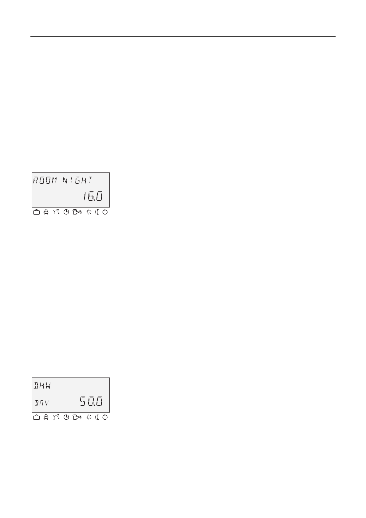
5.1.2.3 "Night-time room temperature" button
Sets the lowered room temperature in automatic mode between
¦
the heating cycles and in the ABSENT and RED. HEATING
operating modes.
In operating mode 1, the set value for all heating circuits is the
same. In operating mode 2, the set value applies for the
respective heating circuit. To set the operating mode, see
5.2.3.3 Operating mode, pg. 74.
Setting
► Press ¦ button.
► Set flashing room temperature specification to the desired
C
Factory setting
Setting range
5.1.2.4 "Daytime hot-water temperature" button
§
Setting
value by turning the input button
î.
► Confirm set value by pressing the ¦ button or the input
button î.
Alternative: Automatic acceptance of the value after the set
information time (see 5.1.2.7 "System information" button, pg. 35).
16 °C
5 ... 30 °C
Sets the daytime hot-water temperature during the hot-water
operational-readiness times in automatic mode and in the PARTY
and HEATING operating modes. This set value also applies for
exclusively hot-water operation (manual summer operation).
► Press § button.
► Set flashing hot-water temperature to the desired value by
C
turning the input button î.
► Confirm set value by pressing the § button or the input
button î.
Alternative: Automatic acceptance of the value after the set
information time (see 5.1.2.7 "System information" button, pg. 35).
Factory setting
50 °C
EN2H-0221GE51 R0808 25
Page 26

Operation SDC / DHC
Setting range
One-time hot-water
circuit loading
5.1.2.5 "Operating mode" button (basic display)
5 °C (hot-water economy temperature) ... Maximum hot-water
heater temperature limit (service setting)
Pressing and holding (approx. 3 s) the § button brings you to
the reload function, where the reload time can be set in minutes.
With a reload time of 0 minutes, loading is started once and the
hot-water tank is loaded to the daytime setpoint. The time for this
superimposed hot-water circuit loading can be set between 0 and
240 minutes. The current week program is superimposed here.
Sets the operating mode and returns to the basic display from
every operating level.
26 EN2H-0221GE51 R0808
Page 27
SDC / DHC Operation
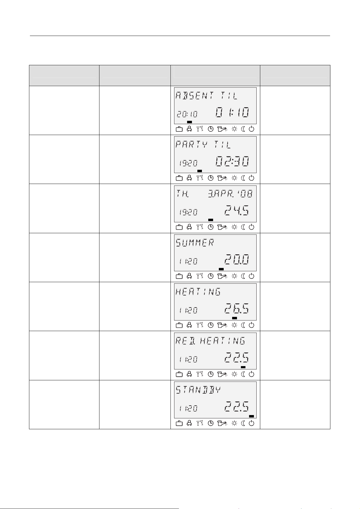
Overview of the operating modes
Symbol Operating mode Display Setting
ç
è
é
ê
ABSENT
PARTY
AUTOMATIC
SUMMER
P1 (P2, P3)*, return
date
P1 (P2, P3)*,
party end time
P1 (P2, P3)*
C
P1(P2, P3)*
C
ë
ì
í
HEATING
RED. HEATING
STANDBY
* P2 and P3 only after enabling, see "System Parameters"
menu, parameter 2 = P1 to P3
C
C
C
EN2H-0221GE51 R0808 27
Page 28
Operation SDC / DHC
The selected operating mode appears in plain text, whereby a
marking at the bottom edge of the display points to the respective
operating mode symbol at the same time. In operating mode 1,
the set value for all heating circuits is the same. In operating
mode 2, the set value applies for the respective heating circuit. To
set the operating mode, see 5.2.3.3 Operating mode, pg. 74.
Setting
► Press button.
► Select operating mode by turning the input button î. The
marking is located above the corresponding operating mode
symbol.
► Confirm set operating mode by pressing the button or the
input button î.
► With short-term operating modes (ABSENT, PARTY), set the
Return to the basic
display
NOTE
5.1.2.5.1 Absence mode (short-term program)
desired value by turning the input button î and confirm with
the button or the input button î.
Alternative: Automatic acceptance of the value after the set
information time (see 5.1.2.7 "System information" button, pg. 35).
Press the button for approx. 3 s to return to the basic display
from any operating level.
Holiday mode is set via the "Switching time programs / Holiday
programs" button (see 5.1.2.6 "Switching time programs / Holiday
programs" button, pg. 33).
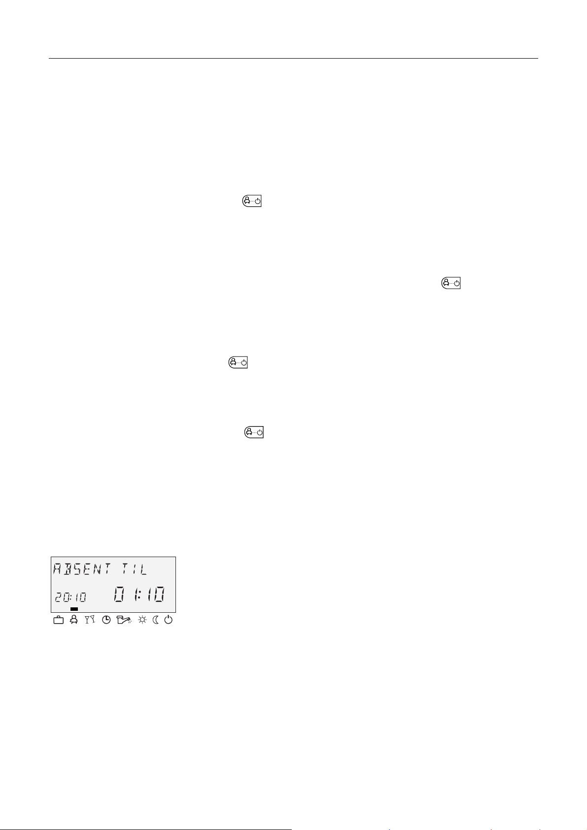
With the ABSENT operating mode, heating operation is
temporarily deactivated and protected from frost during brief
absences. During the absence, all heating circuits are adjusted to
the specified lowered room temperature. Once the set time
expires, the heating circuits automatically return to the operating
mode that was active before the switch to the absence operation.
Short-term programs such as PARTY or ABSENT are skipped
here.
Setting
Application
See 5.1.2.5 "Operating mode" button (basic display) , pg. 26
Short absence while heating operation is active.
28 EN2H-0221GE51 R0808
Page 29
SDC / DHC Operation
Cancellation
Factory setting
Setting range
An active absence program can be cancelled in case of early
return.
► Press button.
► Turn input button î and switch to automatic operation.
The active absence program has been cancelled.
P1 as from activation
P1 (P2, P3) / 0.5 to 24 h to the current time
P1 (P2, P3)
Program-controlled resumption of heating operation. After
activation of the absence program, heating operation is
interrupted until the following switch-on time of the current
automatic program P1 (or P2 or P3, if enabled).
0,5 ... 24 h
The set value is added on to the current time and represents the
return time. When the absence program is called up again, the
last set value is saved and suggested as the initial value.
Display
An active absence program appears in the basic display with
information on the return time.
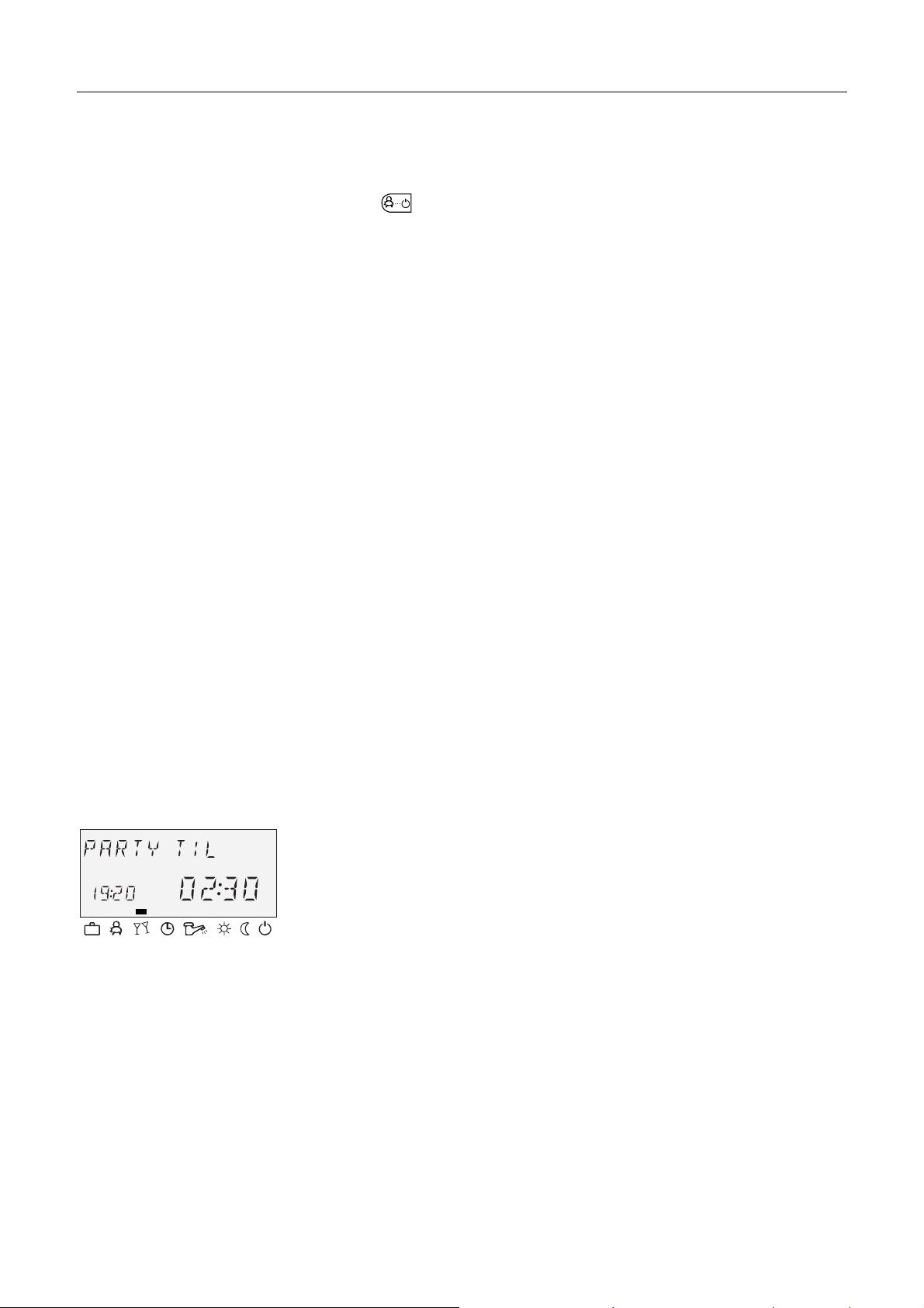
5.1.2.5.2 Party mode (short-term program)
Party mode causes one-time intermediate heating of all heating
circuits up to a specified point in time and bridges an upcoming or
already active absence cycle totally or partially. Once the set time
expires, the heating circuits automatically return to the operating
mode that was active before the party program. Short-term
programs such as ABSENT or PARTY are skipped here.
Setting
Application
See 5.1.2.5 "Operating mode" button (basic display) , pg. 26
One-time extension of heating operation or intermediate heating
during lowering operation outside the schedule.
EN2H-0221GE51 R0808 29
Page 30
Operation SDC / DHC
Cancellation
Factory setting
Setting range
Display
An active party program can be cancelled early.
► Press button.
► Turn input button î and switch to automatic mode.
The active party program has been cancelled.
P1 as from activation
P1 (P2, P3) / 0.5 to 24 h to the current time P1
P1 (P2, P3)
Program-controlled resumption of heating operation. After
activation of the party program, heating operation is continued
until the following switch-on time of the current automatic program
P1 (or P2 or P3, if enabled)
0,5 ... 24 h
The set value is added on to the current time and represents the
end of the party time. When the party program is called up again,
the last set value is saved and suggested as the initial value.
An active party program appears in the basic display with
information on the party end time.
5.1.2.5.3 Automatic mode
In automatic operation, max. three time programs with different
heating operation times are available. They are called up during
C
start-up as factory-set and unlosable default programs P1, P2 or
P3 and can, if necessary, be overwritten with their own switching
times in the "Timeprograms" menu (see 5.2.2 "Timeprograms"
menu, pg. 55).
NOTE
Default programs P2 and P3 cannot be selected until the
PROGRAM = P1 to P3 parameter is enabled in the "System
Parameters" menu. Without enabling, only program P1 is active.
Setting
See 5.1.2.5 "Operating mode" button (basic display) , pg. 26
30 EN2H-0221GE51 R0808
Page 31

SDC / DHC Operation
Disabling / enabling default program P2 to P3
Disabling
"System Parameters" menu, program parameter = P1. All heating
circuits and the hot-water circuit solely refer to the default /
C
individually programmed switching times in the program P1
parameter. Program P1 does not appear in the display in this
operating mode (see 5.2.2 "Timeprograms" menu, pg. 55 and
5.2.3.2 Time program, pg. 73).
Enabling
"System Parameters" menu, program parameter = P1 to P3 (see
5.2.2 "Timeprograms" menu, pg. 55 and 5.2.3.2 Time program,
C
pg. 73).
Display
An active automatic program appears in the basic display with the
current date and time. If default programs P2 and P3 were
enabled, the corresponding symbol, Â,Ã or Ä, is also
displayed depending on the selected program. The symbols are
only displayed with the time program P1 to P3 active.
5.1.2.5.4 Manual summer operation (excluding heating operation)
With manual summer operation, only the hot-water circuit remains
operation and controls the heat generator temperature based on
C
the specified hot-water temperature and the specified hot-water
switching time program. Heating operation is stopped, and
protection from frost is provided. This feature is only available
when control mode is set to 1.
Setting
See 5.1.2.5 "Operating mode" button (basic display) , pg. 26
Disabling / enabling default programs P2 to P3
Disabling
"System Parameters" menu, program parameter = P1. All heating
circuits and the hot-water circuit solely refer to the default /
C
individually programmed switching times in the time program = P1
parameter. Program P1 does not appear in the display in this
operating mode (see 5.2.2.1 Selection of the control circuit, pg. 56
and 5.2.3.2 Time program, pg. 73).
EN2H-0221GE51 R0808 31
Page 32

Operation SDC / DHC
Enabling
"System Parameters" menu, program parameter = P1 to P3 (see
5.2.2.1 Selection of the control circuit, pg. 56 and 5.2.3.2 Time
C
program, pg. 73).
Display
Manual summer operation appears in the basic display with the
information SUMMER. If default programs P2 and P3 were
enabled, the corresponding symbol, Â, Ã or Ä, is also
displayed depending on the selected program. The symbols are
only displayed with the time program P1 to P3 active.
5.1.2.5.5 Continuous heating operation
The HEATING operating mode ensures continuous heating
operation without time limitations based on the specified daytime
C
room temperature. Hot-water production occurs continuously
based on the specified daytime hot-water temperature.
NOTE
The HEATING operating mode remains active until another
operating mode is activated.
Display
Activated continuous heating operation appears in the basic
display with the information HEATING.
5.1.2.5.6 Continuous lowering operation
The RED. HEATING operating mode causes continuously
reduced heating operation based on the specified lowered room
C
temperature. On the heating circuit levels, the reduced operating
mode ECO (frost-protected deactivation mode) or RED (lowering
mode) is set accordingly. The minimum temperature limit of the
respective heating circuit must be taken into account.
See the "Direct Circuit" or "Mixed Heating Circuit 1" / "Mixed
Heating Circuit 2" menu, reduced parameter = reduced operation
and 12 parameter = minimum temperature limit.
Hot-water production occurs continuously based on the specified
hot-water economy temperature (see "DHW" menu, hot water
parameter = hot water at night).
32 EN2H-0221GE51 R0808
Page 33

SDC / DHC Operation
NOTE
Display
C
Application
NOTE
The RED. HEATING operating mode remains active until another
operating mode is activated.
Activated continuous lowering operation appears in the basic
display with the information RED. HEATING.
In standby mode, the entire system is switched off and protected
from frost (all frost-protection functions active).
Hot-water production is disabled and protected from frost. At
storage temperatures below 5 °C, a reload to up to 8 °C takes
place.
Total deactivation of heating and hot water with full building
protection.
The heat generator and hot-water production remain in operation
in case of external demand or demand by other heating circuits
on the bus network. The heating circuit pumps are switched on
briefly every day (pump anti-blocking protection).
The standby mode remains active until another operating mode is
activated.
Display
Activated continuous standby mode appears in the basic display
with the information STANDBY.
5.1.2.6 "Switching time programs / Holiday programs" button
Using this button, you can create individualised switching time
programs for heating and hot-water operation and set holiday
mode.
See 5.1.2.6.1 Holiday mode, pg. 34 and 5.2.2 "Timeprograms"
menu, pg. 55.
EN2H-0221GE51 R0808 33
Page 34

Operation SDC / DHC
5.1.2.6.1 Holiday mode
In holiday mode, the heating circuits can be switched off and
protected from frost or operated based on the settings for the RED.
HEATING operating mode for the duration of the holiday based on
the presetting ("Direct circuit" or "Mixed heating circuit 1" / "Mixed
heating circuit 2" menu, parameter 25 = holiday operating mode).
Setting
► Press button.
The menu-selection level Switching time programs / Holiday
programs appears in the display.
► Turn input button î to the left.
HOLIDAY appears in the display.
► Press input button î.
HOLIDAY 01 appears in the display.
Application
► Press input button î.
The year flashes in the display.
► Set year with the input button î.
► Press input button î.
The day on which the holiday is to begin flashes in the display.
► Set the day the holiday will begin with the input button î.
► Press input button î.
TIL - - appears in the display.
► Set the day you will return from holiday with the input
button î.
► Press input button î.
The desired holiday timeframe is saved.
You can now enter additional holiday timeframes (up to 15 holiday
blocks).
Longer absence while heating operation is active.
34 EN2H-0221GE51 R0808
Page 35

SDC / DHC Operation
Control during
holidays
Cancellation
Factory setting
Setting range
Display
At outside temperatures below the frost-protection limit (see
5.2.3 "System Parameters" menu, pg. 72) the heating circuits are
controlled as follows:
• Without wall devices: Based on a lowered room temperature
specification of 3 °C.
• With wall devices: Based on the room frost-protection limit of
the respective heating circuit of 10 °C (see "Direct Heating
Circuit" or "Mixed Heating Circuit 1", "Mixed heating circuit 2"
menu, parameter 08 = room frost-protection limit).
An active holiday program can be cancelled in case of early
return.
► Press and hold the button for approx. 3 seconds until the
following appears in the display: "Holiday off".
Current date
Current date... (current date + 250 days)
An active holiday program appears in the basic display with
information on the return date.
5.1.2.7 "System information" button
Calls up system information, such as temperatures and counter
¤
data.
The information on the outside temperature appears first after the
¤ button is pressed. Turning the input button î causes the
system temperatures and the counter and consumption states
and operating states of the connected system components to
appear. Pressing the input button
setpoint values to appear.
Exceptions
NOTE
Collector flow temperature: No setpoint
Solar tank temperature: No setpoint
Outside temperature: Averaged value
The displayed information (see the following example) is
independent of the installed or enabled system components and
control circuits.
î causes the respective
EN2H-0221GE51 R0808 35
Page 36

Operation SDC / DHC
Operating overview
Press button
Turn input button to the left Turn input button to the right
Program/operating mode
direct heating circuit/pump status
Program/operating mode
mixed heating circuit 1/pump status
Actuator of
mixed heating circuit 1/status
Program/operating mode
mixed heating circuit 2/pump status
Actuator of
mixed heating circuit 2/status
Average/current outside
temperature value
Outside temperature
min. to max. (0:00 to 24:00 hours)
Heat generator temperature
setpoint/actual value
Hot-water temperature
setpoint/actual value
Flow temperature
setpoint/actual value
Flow temp of mixed heating circuit 1
setpoint/actual value
Program/operating mode
hot-water circuit/pump status
Heat generator
status
Direct heating circuit
pump function/status
Variable output 1
function/operating state
Variable output 2
function/operating state
Flow temp of mixed heating circuit 2
setpoint/actual value
Variable input 1
setpoint/actual value
Variable input 2
setpoint/actual value
Variable input 2
setpoint/actual value
Operating hours
Activations of heat generator
36 EN2H-0221GE51 R0808
Page 37

SDC / DHC Operation
Setting time for
automatic return
Setting range
Factory setting
5.1.2.7.1 Temperature displays
If the ¤ button is pressed and held for approx. 3 s, the INFO
TIME parameter appears.
With this parameter, the time it takes for automatic return to the
basic display can be specified.
OFF No return. The last selected information display
continuously remains in the basic display until the
next change.
1 ... 10 min Automatic return from the information level after the
specified time (in 0.5 minute increments).
OFF
Information Display Condition Remarks
Outside
temperature (1)
Determined
value/Current
value
Outside
temperature (1)
Outside
temperature (2)
Min./max. value
(0:00 to 24:00
hours)
Determined
value/Current
Outside sensor
connected and no fault
message
Variable input
configured as OS2
Connection OS2 to variable
input VI1, VI2 or VI3
value
Outside
temperature (2)
Min./max. value
(0:00 to 24:00
OS2 connected, no fault
message
hours)
EM-SET (energy
management
setpoint)
Heat generator
temperature (1)
"EM-SET" Highest hot-water setpoint
and highest heating circuit
setpoint in the system
Setpoint/Actual
value
Heat generator
specified
Code 1 only appears if BS2
is present
Heat generator
temperature (2)
Setpoint/Actual
value
Variable input
configured as BS2
Connection BS2 to variable
input VI1, VI2 or VI3
EN2H-0221GE51 R0808 37
Page 38

Operation SDC / DHC
Information Display Condition Remarks
Return
temperature
Flow sensor of
district heating
valve VF1
Return sensor of
district heating
valve VFB
External heat
generator disable
Flue gas
temperature
Water heater
temperature (1)
Setpoint/Actual
value
Setpoint/Actual
value
Setpoint/Actual
value
Disabled mode
ON/OFF
Limit signal
value/Actual
value
Setpoint/Actual
value
Return sensor
connected and one of
the functions for return
increase is active
With district heating
With district heating
External heat generator
disable (VI1-VI3)
specified
Variable input
configured as AGF
If hot-water circuit is
present
Connection of return sensor
to associated variable input
1 or 2, VI can no longer be
called up
controllers
controllers
External contact to variable
input VI1, VI2 or VI3
Connection only to variable
input VI1
Code 1 only appears if SF2
is present
Water heater
temperature (2)
Water heater
temperature
controller
Demand via
switching contact
(VI1)
Demand via
switching contact
(VI2)
Demand via
switching contact
(VI3)
Mixed heating
circuit 1 flow
temperature
Setpoint/Actual
value
Load condition
ON/OFF
Demand
ON/OFF
Demand
ON/OFF
Demand
ON/OFF
Setpoint/Actual
value
Variable input
configured as SF2
Thermostat mode Thermostat instead of sensor
VI configured as
demand contact
VI configured as
demand contact
VI configured as
demand contact
Mixed heating circuit 1
specified
Connection to variable input
VI1, VI2 or VI3
(SF1 only)
External contact to variable
input VI1, VI2 or VI3
External contact to variable
input VI1, VI2 or VI3
External contact to variable
input VI1, VI2 or VI3
Mixed heating
circuit 1 return
temperature
38 EN2H-0221GE51 R0808
Actual value Return temperature with
return maximum limit
Page 39

SDC / DHC Operation
Information Display Condition Remarks
Mixed heating
circuit 2 flow
temperature
Mixed heating
circuit 2 return
temperature
Direct heating
circuit room
temperature
Mixed heating
circuit 1 room
temperature
Mixed heating
circuit 2 room
temperature
Setpoint/Actual
value
Actual value Return temperature with
Setpoint/Actual
value
Setpoint/Actual
value
Setpoint/Actual
value
Mixed heating circuit 2
specified
return maximum limit
Direct heating circuit
specified
Mixed heating circuit 1
specified
Mixed heating circuit 2
specified
Setpoint inquiry without room
temperature sensing:
Current room setpoint of
direct heating circuit
Setpoint inquiry without room
temperature sensing:
Current room setpoint of
mixer heating circuit 1
Setpoint inquiry without room
temperature sensing:
Current room setpoint of
mixed heating circuit 2
Direct heating
circuit thermostat
function
Mixed heating
circuit 1
thermostat
function
Mixed heating
circuit 2
thermostat
function
Solid fuel boiler
temperature
Solid fuel boiler
buffer
temperature
DC
THERMOSTAT
MC1
THERMOSTAT
MC2
THERMOSTAT
Actual value VO1/2 configured as
Actual value Solid fuel loading pump at
Thermostat function
specified
Thermostat function
specified
Thermostat function
specified
solid fuel loading pump
OFF = temperature limit
exceeded
OFF = temperature limit
exceeded
OFF = temperature limit
exceeded
Connection of FSKF to
associated variable input 1
or 2, VI can no longer be
called up
variable output, corresponds
to KSPF or FPF, depending
on configuration
EN2H-0221GE51 R0808 39
Page 40

Operation SDC / DHC
Information Display Condition Remarks
Buffer tank
temperature at
top
Buffer tank
temperature at
bottom
Solar collector
flow temperature
Solar tank
temperature
Solar collector
return
temperature
Solar tank switchover temperature
Setpoint/Actual
value
Setpoint/Actual
value
Actual value VO1/2 configured as
Actual value VO1/2 configured as
Actual value VO1/2 configured as
Actual value Solar loading valve activated
VO1/2 configured as
buffer tank loading
pump
VO1/2 configured as
buffer tank loading
pump
solar tank loading pump
solar tank loading pump
solar tank loading pump
Connection of PF1 to
associated variable input 1
or 2, VI can no longer be
called up
Connection of PF2 to
variable input VI1, VI2 or VI3
Special sensor
Connection of KRLF to
variable input VI1, VI2 or VI3
5.1.2.7.2 Operating states
An operating state inquiry occurs after the information menu is
called up by turning the input button anti-clockwise. The following
displays appear only under the specified conditions and may not
be available (depends on device version).
Information Display Condition Remarks
Direct heating
circuit operating
status
Mixed heating
circuit 1 operating
status
Direct heating circuit
specified
Mixed heating circuit 1
specified
Heating program: Holiday,
Absent Til, Party Til, Auto,
Summer, Heating, Red.
Heating, Standby
Switching time program:
P1 (P2, P3) control mode:
Day, RED, ECO
Heating program: Holiday,
Absent Til, Party Til, Auto,
Summer, Heating, Red.
Heating, Standby
Switching time program:
P1 (P2, P3) control mode:
Day, RED, ECO
40 EN2H-0221GE51 R0808
Page 41

SDC / DHC Operation
Information Display Condition Remarks
MC1 actuator
operating status
Mixed heating
circuit 2 operating
status
MC2 actuator
operating status
District heating
valve operating
status
Heat generator
operating status
(st. 1)
Mixed heating circuit 1
specified
Mixed heating circuit 2
specified
Mixed heating circuit 2
specified
District heating valve
opens, closes or does
not move
Heat generator specified Information on the switching
Mixed heating circuit 1
opens, closes or does not
move
Heating program: Holiday,
Absent Til, Party Til, Auto,
Summer, Heating, Red.
Heating, Standby
Switching time program:
P1 (P2, P3) control mode:
Day, RED, ECO
Mixed heating circuit 2
opens, closes or does not
move
With district heating
controllers
state of the multi-stage heat
generator
Heat generator
operating status
(st. 2)
Operating status
of modulating
heat generator
Hot-water circuit
operating status
Multi-stage heat
generator specified
Modulating burner
specified
Hot-water circuit
specified
Information on the switching
state of the second stage of
the heat generator
If a single-stage modulating
heat generator is set,
display of actual value and
setpoint occurs in %
Hot-water program: Holiday,
Absent Til, Party Til, Auto,
Summer, Heating, Red.
Heating, Standby
Switching time program:
P1 (P2, P3) control mode:
Day, RED, ECO
EN2H-0221GE51 R0808 41
Page 42

Operation SDC / DHC
Information Display Condition Remarks
Function and
status of direct
heating circuit
pump
Function and
status of variable
output 1
Outputs specified
based on function
Outputs specified
based on function
Solar (SOP), circulation
(CIR), electric heating rod
(ELH), feeder (CHP), boiler
circuit (KKP1, KKP2), fault
message (SMA), return
(RLP), buffer (PLP), solid
fuel (FSP), heating circuit
(HKP), constant (KP), timer
(CLOCK)
Solar (SOP), circulation
(CIR), electric heating rod
(ELH), feeder (CHP), boiler
circuit (KKP1, KKP2), fault
message (SMA), return
(RLP), buffer (PLP), solid
fuel (FSP), heating circuit
(HKP), constant (KP), timer
(CLOCK)
Function and
status of variable
output 2
District heating
valve volume flow
District heating
valve capacity
Heat generator
(1) start-ups
Outputs specified
based on function
Heat generator specified With district heating
Heat generator specified With district heating
Heat generator specified Information on the number
Solar (SOP), circulation
(CIR), electric heating rod
(ELH), feeder (CHP), boiler
circuit (KKP1, KKP2), fault
message (SMA), return
(RLP), buffer (PLP), solid
fuel (FSP), heating circuit
(HKP), constant (KP), timer
(CLOCK)
controllers
controllers
of heat generator switch-ons
(burner start-ups) of the
multi-stage heat generator.
Operating hours
of heat generator
(1)
42 EN2H-0221GE51 R0808
Heat generator specified Information on the number
of heat generator operating
hours of the multi-stage heat
generator.
Page 43

SDC / DHC Operation
Information Display Condition Remarks
Heat generator
switch-ons stage
2
Heat generator
operating hours
stage 2
Test temperature
for measurement
purposes
Operating status
of ext. switching
modem
Multi-stage heat
generator specified
Multi-stage heat
generator specified
KVT sensor connected
and VI configured.
VI configured as
switching modem
Information on the number
of heat generator switch-ons
(burner start-ups) of the
second stage.
Information on the number
of heat generator operating
hours of the second stage.
Controller-independent test
temperature, sensor
connection to variable input
VI1, VI2 or VI3
Control modes based on the
switching state of the
modem: AUTO (automatic)
STBY (standby), HEAT
(continuous heating), RED
(continuously reduced).
Solar heating
capacity
Solar heat
balance
Switch-ons
Solar loading
pump
Operating hours
Solar loading
pump
VO1/2 configured as
solar tank loading pump
VO1/2 configured as
solar tank loading pump
VO1/2 configured as
solar tank loading pump
VO1/2 configured as
solar tank loading pump
Solar loading pump at
variable output
Solar loading pump at
variable output
Solar loading pump at
variable output
Solar loading pump at
variable output
EN2H-0221GE51 R0808 43
Page 44

Operation SDC / DHC
5.1.2.8 "Manual mode" / "Emission measurement" button
5.1.2.8.1 Manual mode
If this button is pressed and held longer than 5 s in the basic
display, the controller is switched to manual mode. In this
operating mode, the required heat generator temperature is
specified manually with the input button î according to the
respective heating need.
A controller set to manual mode has no effect in heat circuit
expansion.
The heat generator setpoint is set between the minimum and
maximum heat generator temperatures and appears flashing at
C
C
the bottom left-hand side. The current heat generator temperature
appears statically on the right-hand side in the basic display. The
set switching differential corresponds to the value of automatic
control and is symmetrical to the set value.
Application
NOTE
Controller malfunctions (emergency operation), errors
The maximum heat generator temperature limit is paramount to
the heat generator switching differential and stops the heat
generator in case of exceedance.
Cancellation
With control devices operated purely as a heating circuit
expansion, the setting of the temperature has no effect.
The last value to which the control device adjusted the heat
generator temperature appears as a recommendation.
Press button or button, to return to the last selected
operating mode.
44 EN2H-0221GE51 R0808
Page 45

SDC / DHC Operation
5.1.2.8.2 Emission measurement (not with district heating controllers)
ATTENTION
Emission measurements may only be carried out by the
chimney sweep.
Pressing the button controls the heat generator for a duration
of 20 min based on the set maximum temperature limit. The
remaining time is displayed and counted down.
With two-stage heat generators, both stages are in operation
(measurement at nominal output).
Function
The heat generator is adjusted to the maximum heat generator
temperature. All heating circuits and the hot-water production
adjust their setpoint to the respective maximum temperature.
Application
Cancellation
ATTENTION
There is a danger of scalding by hot water, as the hot-water
temperature can exceed the set setpoint temperature.
Emission measurement by the chimney sweep.
Emission measurement can be cancelled at any time with the
or button.
EN2H-0221GE51 R0808 45
Page 46

Operation SDC / DHC
5.1.2.9 Access to the technician / OEM area
Entering a technician or OEM code enables additional setting
options in the parameter menu. The technician code is: 1234.
For access to the OEM area, please ask your field-service contact
partner.
Procedure:
► Press the and buttons simultaneously. The first
number of the 4-digit code flashes.
► Set the first code number by turning the input button.
► Press the input button. The second number flashes.
► Enter all remaining code numbers as described in Steps 2 and
3. After entering the last code number, the controller is
enabled for the respective area (technician or OEM).
► Press and hold the rotary button longer than 3 seconds. You
reach the menu-selection level and can enter / modify
parameters.
Pressing the button jumps back to the previous selection.
Pressing the button, pressing and holding the input button
longer than 3 seconds or waiting until the set info time expires
causes a jump back to the basic display.
46 EN2H-0221GE51 R0808
Page 47

SDC / DHC Operation
5.1.2.10 Heating curve
Determines the heating curve for the heating circuits.
The heating curve describes the relationship of the flow
C
temperature change to the outside temperature change. With a
larger heating surface, such as with floor heaters, the heating
curve has a less extreme slope than with a smaller heating
surface (e.g. radiators).
The set value refers to the lowest outside temperature used for
heat demand calculation.
ATTENTION
This parameter must be set by the technician and should no
longer be changed.
Setting
► Press and hold input button î for 3 s.
Setting range
► Turn the input button î to select the desired heating circuit (HC,
MC-1 or MC-2) and confirm it by pressing the input button î.
The design temperature (system) appears at the bottom righthand side of the display.
► Press input button î.
The slope of the heating curve appears at the bottom left-hand
side of the display.
► Set the flashing heating curve value by turning the input button
î (design temperature also flashes and is changed
automatically depending on the slope of the heating curve).
► Confirm by pressing the input button î.
Alternative: Automatic acceptance of the value after the set
information time (see 5.1.2.7 "System information" button, pg. 35).
► Press
0,2 ... 3,5
button to return to the basic display.
EN2H-0221GE51 R0808 47
Page 48

Operation SDC / DHC
Factory setting
Direct heating circuit (HC) = 1,5
Mixed heating circuit 1
(MC-1) =
Mixed heating circuit 2
(MC-2) =
1
1
x
x Boiler / flow temperature [°C]
y Outside temperature [°C]
a T
room
[°C]
5.2 Menu-selection level
The control device contains a menu-selection level that is
structured differently, depending on the respective device version.
Access
► Press and hold input button î for approx. 3 seconds.
The menu selection always begins with the TIME – DATE
menu.
► Turn input button î to select additional menus.
y
a
► Press input button
î to confirm the selected menu.
48 EN2H-0221GE51 R0808
Page 49
SDC / DHC Operation
9
Variable input 2
Climate zone
Temperature offset
of heat generator
during hot-water
circuit loading
Room thermostat
function
Room thermostat
function
Burner switching
differential II
Starting point of
flexible district
heating return
temperature
Heat balance
Buffer discharge
protection
Quick hot-water
connection
Variable output 2
test
Fault message 9
Sensor of variable
input 2
8
Variable input 1
Demand contact
module for variable
input 3
Tank discharge
protection
Room frost
protection limit
Room frost
protection limit
Burner switching
differential I
Max. return
temperature
setpoint
Priority parallel
switch-over
Buffer start-up
protection
Switch-over of
base load with
grouping
Variable output 1
test
Fault message 8
Sensor of variable
input 1
7
Variable output 2
Demand contact
module for variable
input 2
Hot-water circuit
control mode
Heating limit
Heating limit
Minimum burner
runtime
Runtime of district
heating valve 2
Heat generator
cycle disable
Follow-up switch-
off differential
Peak-load stage
Tank loading pump
test
Fault message 7
Buffer sensor of
collector
6
Variable output 1
Demand contact
module for variable
input 1
Max. temperature
limit for hot-water
circuit
Sensor control
mode
Runtime of district
heating valve 1
Control mode
Switch-on
differential
extension
Guidance stage
Mixer motor 2 test
Fault message 6
Collector sensor
5
Direct heating
circuit pump output
System frost
protection
Transducer for hot-
water circuit
Limit mode of
maximum limit
Adjustment time
Buffer maximum
temperature limit
Heat generator
cycle disable
Forced discharge
Stage reversal
Mixed heating
circuit pump 2 test
Fault message 5
Mixed heating
circuit 2 flow
sensor
4
Switch-over
Mixed heating
circuit 2 output
Summer/Heat limit
Legionella
protection
temperature
Room factor
Room factor
Maximum
temperature limit
Secondary flow
boost
Collector
maximum
temperature
Switch-off
differential
Buffer switching
differential
Switch-over
capacity of stage
sequence
Mixed heating
circuit 2 bus
authorisation
Mixer motor 1 test
Fault message 4
Mixed heating
circuit 1 flow
sensor
3
Day - Month
Mixed heating
circuit 1 output
Operating mode
Legionella
protection time
Room connection
Room connection
Minimum
temperature limit
District heating
valve minimum
travel
Follow-up time of
pump
Solar loading
pump minimum
runtime
Switch-on
differential
Boiler temperature
offset
Regulation
Switch-off delay
2
Year
Hot-water loading
pump output
Time program
Legionella
protection day
Heating system
Heating system
Start-up protection
Maximum flow
temperature
setpoint limit
Switch-off
differential
Switch-off
differential
Max. temperature
Max. temperature
Connection delay
1
Time
Hydraulic
schematic
Language
selection
Hot water at night
Reduced operation
Reduced operation
Design
0
Heating curve
slope
Heating curve
slope
Offset
Return
temperature
setpoint
Switch-on
differential
Min. temperature
Min. temperature
Regulation
Switching
differential
Mixed heating
Direct heating
circuit 1 bus
circuit bus
Central device
Mixed heating
authorisation
circuit pump 1 test
Fault message 3
Hot-water sensor
authorisation
Direct heating
circuit pump test
Fault message 2
Heat generator
sensor
address
Heat generator
test
Fault message 1
Outside sensor
Parameter
Date
Hydraulics
System parameter
Programming
Configuration
Hot water
Direct heating
circuit
Mixed heating
circuit 1/2
Heat generator
District heating
Return increase
Solar
Configuration
(heating circuits,
control paths)
Solid fuel
Buffer
Total flow control
Cascading
Data bus
Relay test
Fault messages 1/2
Sensor calibration
Service functions
EN2H-0221GE51 R0808 49
Page 50

Operation SDC / DHC
Behaviour
of
heat
Mi
d
h
ti
Mi
d
h
ti
B
ff
l
di
Max
return
loading
19
Frost protection
mode
Sample time Ta
Modulation of
proportional part
Xp
Fault message 19
18
Cycle temperature
enable
P-part Xp
17
16
generator during
extended running
time
Return maximum
Type code
Circulation pump
Screed function
temperature limit
Flue gas
Screed function
Flue gas
temperature
Fault message 18
temperature limit
Fault message 17
monitoring
Switch-over
temperature
Fault message 16
15
14
13
12
11
10
Locking code for
heating technician
Follow-up time of
pump
Follow-up time of
pump
Charging pump
extended running
time
Max. volume flow
Solar loading
switch-over test
cycle
Fault message 15
Automatic set
function
Economy interval
cycle
Temperature offset
of heating circuit
Temperature offset
of heating circuit
Boiler circuit pump
extended running
time
Max. thermal
output
Final switch-off
temperature
Fault message 14
ng
ea
Logical fault
messages
Circulation pump
economy interval
pause
Maximum
temperature limit
Maximum
temperature limit
Flow time of boiler
circuit pump or
parallel heat
generator enable
Calibration of
volume flow
Heat capacity of
medium
Anti-blocking
function
Circulation pump
switching time
program
Minimum
temperature limit
Minimum
temperature limit
Hot-water circuit
loading 1-2 stage
Calibration of
thermal output
Density of medium
ng
oa
er
Indirect return
increase via mixed
heating circuit
Automatic exit time
Hot-water loading
pump extended
running time
Constant
temperature
setpoint
Constant
temperature
setpoint
Boiler start-up
discharge stage II
District heating
valve return limit
Volume flow
.
Variable input 3
Building type
Switching
differential of hot-
water circuit
Assignment of
outside sensor
Assignment of
outside sensor
Connection delay
stage II
temperature
setpoint during
hot-water circuit
Reset heat
balance
u
pump extended
running time
Buffer control
mode
System
xe
Fault message 13
circuit 2 room
sensor
ng
ea
xe
Fault message 12
circuit 1 room
sensor
Fault message 11
Direct heating
circuit room sensor
Fault message 10
Sensor of variable
input 3
Parameter
Date
Hydraulics
System parameter
Programming
50 EN2H-0221GE51 R0808
Configuration
Hot water
Direct heating
circuit
Mixed heating
circuit 1/2
Heat generator
District heating
Return increase
Solar
Configuration
(heating circuits,
control paths)
Solid fuel
Buffer
Total flow control
Cascading
Data bus
Relay test
Fault messages 1/2
Sensor calibration
Service functions
Page 51

SDC / DHC Operation
r
g
Heating
circuit
differential
29
curve for
emergency
operation without
outside senso
Heat generator
forced discharge
28
27
26
Fault memory 2
temperature of
mixed heating
circuit
minimum
temperature limit
switching
Heating circuit
minimum
temperature limit
Room setpoint
ramp
Room setpoint
ramp
Base load offset
25
24
23
22
21
20
Cooling switch-on
temperature
Holiday control
mode
Holiday control
mode
Outside
temperature
disable
Locking code for
Adjustment of the
real time clock
Room control Tn
Room control Tn
Modulation of start
power
operating level
Room control C-
factor
Room control C-
factor
Modulation of start
time
Actuator end
position function
Modulation of
runtime
(RTC)
Actuator runtime
Modulation of
adjustment time Tn
Reset fault
messages
I-part Tn
Modulation of
sample time Ta
Fault message 20
Parameter
Date
Hydraulics
System parameter
Programming
Configuration
Hot water
Direct heating
circuit
Mixed heating
circuit 1/2
Heat generator
District heating
Return increase
Solar
Configuration
(heating circuits,
control paths)
Solid fuel
Buffer
Total flow control
Cascading
Data bus
Relay test
Fault messages 1/2
Sensor calibration
Service functions
EN2H-0221GE51 R0808 51
Page 52

Operation SDC / DHC
39
38
37
36
Hot-water circuit
pre-control spread
Resetting of stage
1 burner start-up
and operating hour
counters
Inverse outside
temperature
disable
Burner counter
mode
35
34
33
32
31
30
Parameter reset
Selection
Hot-water capacity
limit
Heating capacity
limit
SDC/DHC
Full-load control
OEM maximum
limit
Parameter
Date
Hydraulics
System parameter
Programming
Configuration
Hot water
Direct heating
circuit
Mixed heating
circuit 1/2
Heat generator
District heating
Return increase
Solar
Configuration
(heating circuits,
control paths)
Solid fuel
Buffer
Total flow control
Cascading
Data bus
Relay test
Fault messages 1/2
Sensor calibration
Service functions
52 EN2H-0221GE51 R0808
Page 53

SDC / DHC Operation
H
ti
i
it
Offset
valve
control
rcu
ng c
ea
name
47
46
45
Heating circuit
name
Heating circuit
name
Lowering ramp
Lowering ramp
Pre-heat time at
0°C
Pre-heat time at
0°C
Without room
sensor
Without room
sensor
44
43
42
41
40
Parameter
Date
Hydraulics
System parameter
Min. jump back
temperature
Min. jump back
temperature
Max. pre-heat time
Max. pre-heat time
Min. pre-heat time
Min. pre-heat time
Switch-on
optimisation
Switch-on
optimisation
position of hot-
water circuit pre-
Resetting of stage
2 burner start-up
Hot water
Direct heating
circuit
Mixed heating
circuit 1/2
OEM
Heating technician
User
and operating hour
counters
Heat generator
District heating
Return increase
Solar
Solid fuel
Buffer
Total flow control
Cascading
Data bus
Relay test
Fault messages 1/2
Sensor calibration
Programming
Configuration
Configuration
(heating circuits,
control paths)
Service functions
EN2H-0221GE51 R0808 53
Page 54

Operation SDC / DHC
5.2.1 "Time - Date" menu
The following current calendar values can be specified in this
menu:
• Time
• Year
• Day - Month
• Time change mode (summer / winter time)
NOTE
All listed daytime values are set at the factory and generally do
not need to be updated.
An internal, pre-programmed calendar ensures automatic time
change on the annually recurring summer / winter time switchover
dates. If necessary, the automatic time change can be
deactivated. The current weekday, Mo to Su is determined from
the calendar date and does not need to be set.
Application
Access
Setting
Corrections for rare fault cases
See 5.2 Menu-selection level, pg. 48
► Turn input button î and select the "Time - Date" menu.
Returning
► Turn input button î and select the desired calendar value
(time, year, day - month, change).
► Press input button
turning the input button
î and change the corresponding value by
î.
► Press input button î to confirm the set value.
► Turn input button î to select and change additional calendar
values.
Returning to the basic display takes place by pressing the
button or automatically after the set information time (see
5.1.2.7 "System information" button, pg. 35).
54 EN2H-0221GE51 R0808
Page 55

SDC / DHC Operation
5.2.2 "Timeprograms" menu
Individualised switching time programs for heating and hot-water
operation can be created in this menu. Here, the factory-set
default programs P1 (and, if enabled, P2 and P3 as well) of each
heating circuit and the hot-water circuit are overwritten by
individualised switching times and temperature specifications.
This is especially advantageous if correspondingly adapted
heating programs are to be created in case of periodically
recurring assignments with different assignment times (e.g. shift
work). Max. three heating cycles, each with a switch-on and
switch-off time, are available for each day of the week for
programming switching times. Each heating cycle can also be
combined with a freely-selectable temperature specification.
NOTE
The default programs are not lost when overwritten by individually
created programs. Individualised programs, however, are deleted
when default programs are reloaded and must be recreated. For
this reason, individualised switch-on / switch-off times and
temperature specifications should always be entered in the tables
provided for this purpose (see 9 Log, pg. 254).
Access
Returning
Press button.
Returning to the basic display takes place by pressing the
button or automatically after the set information time (see
5.1.2.7 "System information" button, pg. 35).
EN2H-0221GE51 R0808 55
Page 56

Operation SDC / DHC
5.2.2.1 Selection of the control circuit
After accessing the "Timeprograms" menu, the desired control
circuits can be selected with the input button î in the following
sequence:
• Direct heating circuit (HC)
• Mixed heating circuit 1 (MC-1)
• Mixed heating circuit 2 (MC-2)
• Hot-water circuit (DHW)
► Press input button î to access the selected circuit.
5.2.2.2 Selection of the program
If the switching time programs P2 and P3 have been enabled (see
"System Parameter" menu, program parameter = P1 to P3), the
program selection appears.
If switching time programs P2 and P3 are disabled, program
selection is automatically skipped (see "System Parameters"
menu, program parameter = P1).
5.2.2.3 Selection of day of the week and cycle
Once the program is selected, the first cycle of the first day of the
week (MO 1) and the relevant section in the top time bar flash.
The other cycles are selected by turning the input button î and
confirmed by pressing the input button î.
56 EN2H-0221GE51 R0808
Page 57

SDC / DHC Operation
5.2.2.4 Programming switching times and cycle temperatures
5.2.2.4.1 Switch-on time
The switch-on time is the start of heating or, with enabled switchon optimisation, the start of assignment.
After selecting the day of the week and the corresponding cycle,
the respective switch-on time appears flashing and can be set
with the input button î. The time bar in the top part of the display
provides an overview of all programmed cycles between 0:00 and
24:00 hours on the selected day of the week.
NOTE
The switch-on time cannot be set below the switch-off time of a
previous cycle or below 0:00 hours of the selected day of the
week.
If the switch-on time is changed, the corresponding time bar
display is adjusted to the left-hand side.
If the switch-on time is made equal to the switch-off time, the
corresponding cycle is deleted. A subsequent cycle is
automatically shifted to the position of the deleted cycle upon
acceptance.
With subsequent insertion of a cycle that has been bumped up,
the corresponding day of the week must be reprogrammed.
A flashing switch-on time is accepted by pressing the input button
5.2.2.4.2 Switch-off time
The switch-off time is the end of heating or, with enabled switchoff optimisation, the end of assignment.
Once the switch-on time is accepted, the associated switch-off time
appears flashing and can be changed with the input button î. The
time bar in the top part of the display provides an overview of all
programmed cycles between 0:00 and 24:00 hours on the
selected day of the week.
î.
EN2H-0221GE51 R0808 57
Page 58

Operation SDC / DHC
NOTE
5.2.2.4.3 Cycle temperature
The switch-off time cannot be set higher than the switch-on time
of a subsequent cycle.
If the switch-on time is changed, the corresponding time bar
display is adjusted to the right-hand side.
If the switch-off time is made equal to the switch-on time, the
corresponding cycle is deleted. A subsequent cycle is
automatically shifted to the position of the deleted cycle upon
acceptance.
With subsequent insertion of a cycle that has been bumped up,
the corresponding day of the week must be reprogrammed.
A flashing switch-off time is accepted by pressing the input button î.
Once the switch-off time is accepted, the associated cycle
temperature appears flashing and can be changed immediately
with the input button î. With heating circuits, the displayed cycle
temperature is always based on the desired room temperature;
with the hot-water circuit, it is based on the desired normal hotwater temperature in the selected cycle.
A flashing cycle temperature is accepted by pressing the input
button î.
At the same time, the last called-up cycle appears flashing so that
it may be monitored; additional cycles can then be selected
directly and edited in the same way in the order: switch-on time,
switch-off time, cycle temperature.
58 EN2H-0221GE51 R0808
Page 59

SDC / DHC Operation
Switching time programming (programs P2 and P3 disabled)
Upon accessing the menu-selection level, the "Timeprograms"
menu always appears first.
Enabling of programs P2 and P3 in the "System Parameters"
menu (see 5.2 Menu-selection level, pg. 48 ).
Select
heating circuit:
Select day
and cycle:
Change:
Change:
Change:
HC MC -1 MC -2 DHW
MoHcy-1
Start of
heating
End of
heating
Temperature
MoHcy-2
Monitoring
MoHcy-3
Only appears if there are switching
times in the second heating cycle.
TuHcy-1
We
Th
Fr
Sa
Default
time
SuHcy-3
Copy
circuit
Copy
day
Return:
3 s
Return to the basic display:
HC Direct heating circuit
MC-1 Mixed heating circuit 1
MC-2 Mixed heating circuit 2
DHW Hot-water heating circuit
Hcy Heating cycle
EN2H-0221GE51 R0808 59
Page 60

Operation SDC / DHC
Default switching time program (P1) for heating and hot
water
Uniform, continuous heating and hot-water operation on all days
of the week
Default program P1
Heating operation Heating circuit Day
from to
Heat generator heating
circuit
Hot-water circuit Mo to Su 5:00 22:00
Mixed heating circuit 1 / 2 Mo to Su 6:00 22:00
Mo to Su 6:00 22:00
60 EN2H-0221GE51 R0808
Page 61

SDC / DHC Operation
Switching time programming (program P2 and P3 enabled)
Upon accessing the menu-selection level, the "Timeprograms"
menu always appears first. Enabling of programs P2 and P3 in
the "System Parameters" menu (see 5.2 Menu-selection level, pg.
48 ).
Select
heating circuit:
Select
program:
Select day
and cycle:
Change:
Change:
Change:
HC
P1 P2 P3
MoHcy-1
Start of
heating
End of
heating
Temperature
MC -1 MC -2 DHW
MoHcy-2
Monitoring
Default
time
We
MoHcy-3
Only appears if there are switching
times in the second heating cycle
TuHcy-1
Th
Fr
Sa
SuHcy-3
Copy
circuit
Copy day
Return:
3 s
Return to the basic display:
HC Direct heating circuit
MC-1 Mixed heating circuit 1
MC-2 Mixed heating circuit 2
DHW Hot-water heating circuit
Hcy Heating cycle
EN2H-0221GE51 R0808 61
Page 62

Operation SDC / DHC
Default program P1
Heating operation Heating circuit Day
from to
Heat generator heat-
Mo to Su 6:00 22:00
ing circuit
Hot-water circuit Mo to Su 5:00 22:00
Mixed heating
Mo to Su 6:00 22:00
circuit 1 / 2
Default program P2
Heating operation Heating circuit Day
from to from to
Mo to Th 6:00 8:00 16:00 22:00
Boiler heating circuit
Fr 6:00 8:00 13:00 22:00
Sa to Su 6:00 22:00
Mo to Th 5:00 8:00 15:30 22:00
Hot-water circuit
Fr 5:00 8:00 12:30 22:00
Sa to Su 6:00 23:00
Mixed heating
circuit 1 / 2
Default program P3
ing circuit
circuit 1 / 2
Mo to Th 6:00 8:00 16:00 22:00
Fr 6:00 8:00 13:00 22:00
Sa to Su 7:00 23:00
Heating operation Heating circuit Day
from to
Mo to Fr 7:00 18:00 Heat generator heat-
Sa to Su Reduced
Mo to Su 6:00 18:00 Hot-water circuit
Sa to Su Reduced
Mo to Su 7:00 18:00 Mixed heating
Sa to Su Reduced
62 EN2H-0221GE51 R0808
Page 63

SDC / DHC Operation
5.2.2.4.3.1 Copying switching time programs (days)
Block programming enables the switching times and cycle
temperatures of any day of the week to be copied
1 – To any days within the week (Mo, Tu, We, ..., Su)
2 – To all weekdays (Mo to Fr)
3 – To the weekend (Sa to Su)
4 – To the entire week (Mo to Su)
Calling up the copy function (days)
See flowcharts on pg. 65
Source day
► Press input button î to confirm the copy function.
Target day
► Turn input button î to select the source day (MO to SU) to be
copied.
The respective automatic program P1 (P2, P3) of the source
day is copied in the display with the time switch symbol and
the program index.
► Press input button î to confirm the source day.
The source day appears flashing.
► Turn input button î to select the following setting values and
confirm by pressing the input button
î:
• The following target days (Mo to Su) individually
• All days of the week (1 to 7) as a week block
• All weekdays (1 to 5) as a weekday block
• The weekend days (6 to 7) as a weekend block
Acceptance is confirmed by acknowledging DAY COPY OK.
After acknowledgement, the following target days appear one
after another automatically with each additional press of the input
button
î and can be skipped and accepted if necessary.
Pressing the button causes an immediate return to the basic
display.
NOTE
Only complete days with all cycles and temperature specifications
and the respective program can be copied.
EN2H-0221GE51 R0808 63
Page 64

Operation SDC / DHC
5.2.2.4.3.2 Copying switching time programs (heating circuits)
Block programming also enables the copying of all switching
times and temperature specifications of a heating circuit to
another heating circuit.
Calling up the copy function (heating circuits)
See flowcharts on pg. 65
Source circuit
► Press input button î to confirm the copy function.
► Turn input button î to select the source circuit to be copied
(HC, MC-1, MC-2, DHW).
If automatic program P1, P2 or P3 (see "System Parameter"
menu, PROGRAM parameter = P1 to P3) was enabled, the
desired switching time program P1, P2 or P3 of the source
circuit can be selected. If not enabled, program selection is
skipped.
Target circuit
► Press input button î, to confirm the source circuit.
Based on the same chart, the desired target circuit and, if
enabled, the desired program can be selected and accepted.
NOTE
Acceptance is confirmed by acknowledging COPY OK. The copy
function is then called up again to copy additional circuits, if
necessary.
Heating circuits cannot be copied to hot-water circuits or the reverse due to the different temperature specifications. If a heating
circuit (HC, MC-1, MC-2) is selected as the source circuit, the hotwater circuit (DHW) switches off as the target circuit.
A hot-water circuit as the source circuit is also the target circuit. In
this case, only switching time programs P1 to P3 are copied
among one another.
Pressing the
button causes an immediate return to the basic
display.
64 EN2H-0221GE51 R0808
Page 65

SDC / DHC Operation
Block programming
The copy function enables a source day to be copied to any target
days or to all days of the week (week programming). All cycles of
the source day are copied. Individual heating cycles cannot be
copied.
ö
Select
heating circuit:
Select program:
Select
copy function:
HC
ö
î
P1 P2 P3
ö
î
Mo
Hcy-1
Mo
Hcy-2
MC -2MC -1
Mo
Hcy-3
DHW
1)
Tu
Hcy-1
We
Th
Fr
Sa
Default
time
Su
Hcy-3
Copy
circuit
Copy day
HC Direct heating circuit
MC-1 Mixed heating circuit 1
MC-2 Mixed heating circuit 2
DHW Hot-water heating circuit
1) Program selection for source and target circuits are
skipped if programs P2 and P3 are disabled in the
"System Parameter" menu.
EN2H-0221GE51 R0808 65
Page 66

Operation SDC / DHC
Copy day
Select
source day:
Example: Monday
Select
first target day:
Example: Tuesday
Copy source day
to first target day:
Acknowledge:
Select
second target day:
Example: Wednesday
Copy
from Mo
Copy Mo
to Tu
Copy
day OK
Copy Mo
to We
Mo ... Su
Source day
1 target day or
1-7 (Mo ... Su) or
1-5 (Mo ... Fr) or
6-7 (Sa ... Su)
Tuesday as with Monday
Source day
Second target day
Copy source day
to second target day
Acknowledge:
Copy
day OK
Wednesday as with Monday
Select and copy other
target days if necessary
Return to the basic display:
66 EN2H-0221GE51 R0808
Page 67

SDC / DHC Operation
Copying heating circuits
Select
copy function:
Select
source circuit:
Select
source circuit
program:
NOTE
Heating circuits cannot be copied to hot-water circuits since they
have different cycle temperatures: If a heating circuit is selected
as the source circuit, the hot-water circuit can no longer be called
up as the target circuit. The hot-water circuit as the source circuit
is also the target circuit. In this case, only programs of the hotwater circuit are copied among one another if they were enabled
in the "System Parameter" menu.
HC MC-1 MC-2 DHW
Source circuit
HC
Source circuit
HC P1
Source circuit
MC -1
Source circuit
MC -1 P2
Source circuit
MC -2
Source circuit
MC -2 P3
Default
time
1)
Copy
circuit
Select
target circuit:
Select
target circuit
program:
Copy:
Acknowledge:
Exit:
Target circuit
HC
Target circuit
MC -2 P1
Copy
-OK-
Basic display
Target circuit
MC -1
Target circuit
MC -2 P2
Target circuit
MC -2
Target circuit
MC -2 P3
1)
Program P1 (direct heating circuit) =
Program P2 (mixed heating circuit 2)
Copy additional heating circuits
if necessary
EN2H-0221GE51 R0808 67
Page 68

Operation SDC / DHC
HC Direct heating circuit
MC-1 Mixed heating circuit 1
MC-2 Mixed heating circuit 2
DHW Hot-water heating circuit
1) Program selection for source and target circuits are
skipped if programs P2 and P3 are disabled in the
"System Parameter" menu.
5.2.2.4.4 Reloading default programs
See flowchart on pg. 70
Individually created switching time program P1, P2 or P3 can be
overwritten with the original default switching time program P1, P2
or P3.
Resetting
For this purpose, select the DEFAULT-TIME function within the
heating circuit selection after accessing the "Timeprograms"
menu.
After confirming by pressing the input button î, the circuit
dedicated to reloading appears flashing (HC, MC-1, MC-2, ALL).
If the automatic programs P1, P2 and P3 (see "System
Parameter" menu, program parameter = P1 to P3) were enabled,
the desired switching time program P1, P2 or P3 of the heating
circuit affected by the reload can be selected. If not enabled,
program selection is skipped.
Resetting then occurs by pressing and holding the input button
approx. 5 s until acknowledgement appears in the display.
Resetting is confirmed by acknowledging COPY OK.
The DEFAULT-TIME function is then called up again to replace
other circuits with their default programs if necessary.
68 EN2H-0221GE51 R0808
Page 69

SDC / DHC Operation
ATTENTION
With the setting value ALL, all heating circuits and the hotwater circuit are overwritten with their default switching
times with regard to the selected program.
When overwriting occurs, individually created switching time
programs are permanently lost and must be recreated from
scratch.
Pressing the button causes an immediate return to the basic
display.
EN2H-0221GE51 R0808 69
Page 70

Operation SDC / DHC
Reloading default programs
Switching time programs P2 and P3 disabled
HC Direct heating circuit
MC-1 Mixed heating circuit 1
MC-2 Mixed heating circuit 2
DHW Hot-water heating circuit
70 EN2H-0221GE51 R0808
Page 71

SDC / DHC Operation
Reloading default programs
Switching time programs P2 and P3 enabled
DHW
HC Direct heating circuit
MC-1 Mixed heating circuit 1
MC-2 Mixed heating circuit 2
DHW Hot-water heating circuit
EN2H-0221GE51 R0808 71
Page 72

Operation SDC / DHC
5.2.3 "System Parameters" menu
The system parameters refer to general limiting parameters and
specification values within the heating system.
Access
Returning
See 5.2 Menu-selection level, pg. 48
Returning to the basic display takes place by pressing the
button or automatically after the set information time (see
5.1.2.7 "System information" button, pg. 35).
5.2.3.1 Language selection
Several languages can be selected for all information that
appears in the display.
Setting values
After selecting the language and confirming it by pressing the
input button î, additional communication takes place in the
respective language.
DE German
GB English
FR French
IT Italian
NL Dutch
ES Spanish
PT Portuguese
HU Hungarian
CZ Czech
PL Polish
RO Romanian
RU Russian
TR Turkish
S Swedish
N Norwegian
Factory setting
German
72 EN2H-0221GE51 R0808
Page 73

SDC / DHC Operation
5.2.3.2 Time program
This parameter specifies enabling of the switching time programs
for program selection and for individualised switching time
programming. In the state of delivery, only one switching time
program is enabled. This achieves simplification of operation with
a large portion of applications for which only one switching time
program is used.
Set values
P1 Program 1 = enabled, programs 2 and 3 = disabled
P1 to P3 All three programs enabled
Factory setting
Effects
P1
In contrast to the previous description, the following setting
options are available when programs P1 to P3 are enabled:
• Operating mode selection: In the AUTOMATIC and SUMMER
operating modes, switching time program P1, P2 or P3 can be
selected.
• Switching time programming: With switching time pro-
gramming, the three switching time programs, P1 to P3, can
be selected for each heating circuit.
5.2.3.2.1 Control mode selection
In the AUTOMATIC and SUMMER control modes, switching time
program P1, P2 or P3 can be selected.
5.2.3.2.2 Switching time programming
With switching time programming, the three switching time
programs, P1 ... P3 can be selected.
EN2H-0221GE51 R0808 73
Page 74

Operation SDC / DHC
5.2.3.3 Operating mode
Two operating modes can be selected. They determine whether
the operating mode, the daytime temperature and the night-time
temperature apply for all heating circuits or can be specified
individually for each heating circuit.
Setting range
Set values
1, 2
1 The selected setting applies for all heating circuits together.
2 Each heating circuit can be assigned an individualised set-
ting.
Factory setting
1
5.2.3.3.1 Individualised daytime room temperature for each heating
Setting
C
Setting range
Factory setting
circuit
► Press ¥ button.
► Select desired heating circuit (HC, MC-1 or MC-2) by turning
the input button î.
► Confirm selected circuit by pressing the input button î.
► Set flashing room temperature specification to the desired
value by turning the input button
î.
► Confirm set value by pressing the ¥ button.
Alternative: Automatic acceptance of the value after the set
information time (see 5.1.2.7 "System information" button, pg. 35).
5 ... 30 °C
20 °C
74 EN2H-0221GE51 R0808
Page 75

SDC / DHC Operation
5.2.3.3.2 Individualised night-time room temperature for each heating
circuit
Setting
C
Setting range
Factory setting
5.2.3.3.3 Individualised operating mode for each heating circuit
► Press ¦ button.
► Select desired heating circuit (HC, MC-1 or MC-2) by turning
the input button î.
► Confirm selected circuit by pressing the input button î.
► Set flashing room temperature specification to the desired
value by turning the input button î.
► Confirm set value by pressing the ¦ button.
Alternative: Automatic acceptance of the value after the set
information time (see 5.1.2.7 "System information" button, pg. 35).
5 ... 30 °C
16 °C
Setting
C
Each heating circuit can be assigned an individualised operating
mode.
► Press button.
► Select desired heating circuit (HC, MC-1 or MC-2) by turning
the input button
► Confirm selected circuit by pressing the input button
î.
î.
► Select flashing operating mode by turning the input button î.
► Confirm set operating mode by pressing the button or the
input button î.
► With short-term operating modes (ABSENT, PARTY), set
desired target value by turning the input button î and confirm
set value by pressing the input button î.
Alternative: Automatic acceptance of the value after the set
information time (see 5.1.2.7 "System information" button, pg. 35).
This parameter specifies the end of heating operation depending
on the outside temperature based on the following criteria:
EN2H-0221GE51 R0808 75
Page 76

Operation SDC / DHC
Quick increase in outside temperature
If the averaged outside temperature is below the set value and
the current outside temperature is 2 K above the set value,
heating operation is interrupted.
Slow increase in outside temperature
Deactivation is also initiated when the averaged and current
outside temperature exceeds the set value.
Undoing deactivation
Deactivation is undone when the averaged and current outside
temperature exceeds the set value by 1 K.
The summer deactivation function is undone:
NOTE
Factory setting
Setting range
• In case of an outside sensor defect
• In case frost protection is active
During deactivation phases (standby mode, manual summer
operation, summer deactivation) lasting longer than 24 hours all
pumps are switched on for approx. 20 s and the mixers are
temporarily opened during this time to protect against blocking by
corrosion.
In connection with a second outside sensor, the current averaged
outside temperature is accepted for summer deactivation if the
average value of both sensors is specified during outside sensor
assignment.
Active summer deactivation is represented by a beach umbrella
symbol in the basic display.
Only active in the AUTOMATIC operating mode.
20 °C
OFF, set value of system frost protection to 40 °C
5.2.3.4 Parameter reset
With the reset parameter, it is possible to reset any inadvertently
made changes in the parameter menu to the factory setting.
76 EN2H-0221GE51 R0808
Page 77

SDC / DHC Operation
ATTENTION
A reset should only be carried out if all individually entered
values are to be replaced by the values specified at the
factory.
Setting
► When the PARAM. RESET display flashes, press the input
button î.
SET flashes in the display.
► Press and hold the input button î for 5 s.
If a reset is carried out, the RESET OK confirmation appears
briefly. Verification is then started with a call-up of the first
parameter in the respective menu once again.
After the parameter values are reset, a return to the first
parameter in the "System Parameter" menu occurs.
5.2.3.5 Complete reset
To reset all settings, a complete reset of the device can be carried
out.
A complete reset is initiated when the , ¥, ¦ and § keys
are pressed simultaneously until the controller restarts.
5.2.4 "DHW" menu
This menu contains all parameters required to program the hotwater circuit, except the hot-water switching time programs.
EN2H-0221GE51 R0808 77
Page 78

Operation SDC / DHC
5.2.4.1 Night-time hot-water temperature
This parameter specifies the temperature in the hot-water
generator between the operational-readiness times in automatic
mode.
Factory setting
Setting range
NOTE
40 °C
5 °C to set normal hot-water temperature value
If a hot-water thermostat (see parameter 05 = transducer for hotwater circuit) is used to detect the hot-water temperature, this
parameter is skipped.
5.2.4.2 Legionella protection day
Factory setting
Setting range
Set values
NOTE
5.2.5 "Direct Heating Circuit" / "Mixed Heating Circuit 1" / "Mixed
OFF
OFF, MO to SU, ALL
OFF The legionella protection function is not active.
MO to SU Legionella protection is activated on the selected
day of the week at the legionella protection time set
in the following parameter.
ALL The legionella protection function is activated daily
at the legionella protection time set in the next
parameter.
If a hot-water thermostat (see 05 parameter = transducer for hotwater circuit) is used to detect the hot-water temperature, these
parameters are skipped.
Heating Circuit 2" menu
These menus contain all parameters required to program the
heating circuit, except the switch time programs. Max. one direct
heating circuit and two mixed heating circuits (mixed heating
circuit 1 and mixed heating circuit 2) are available as heating
circuits.
The following described heating circuit parameters are available
separately for setting for each heating circuit.
78 EN2H-0221GE51 R0808
Page 79

SDC / DHC Operation
5.2.5.1 Reduced operation
During reduced operation, you can select between two operating
modes.
Factory setting
Setting range
Set values
ECO
ECO, RED
RED (lowering operation)
The heating circuit pump of the direct heating circuit continues
functioning during reduced operation (see 5.2.3.2 Time program,
pg. 73). The flow temperature is determined based on the lowered
room temperature from the associated reduced heating curve.
The set maximum temperature is not undershot.
Application
Building with minimal insulation values and high cooling loss.
Application
NOTE
ECO (switch-off operation)
During reduced operation, the direct heating circuit is switched off
completely with outside temperatures above the set frostprotection limit. The maximum heat generator temperature is not
functional. The heating circuit pump is switched off after a delay to
avoid safety deactivation by reheating the heat generator (pump
follow-up).
If the outside temperature is or becomes lower than the specified
outside temperature frost-protection limit, the controller switches
from deactivated (deactivation mode) to lowered lowering
operation and controls the heating circuit temperature based on
the set lowering curve taking the set minimum heat generator
specification into account.
Building with high insulation values (full heating protection).
The mode set here also applies for the ABSENT and RED.
HEATING operating modes.
EN2H-0221GE51 R0808 79
Page 80

Operation SDC / DHC
5.2.5.2 Heating system
This parameter refers to the type of the heating system (floor,
radiator or convector heating) and can be matched to the
exponent of the respective heat distributor. Using its progressive
characteristics, the set value determines the curve characteristics
of the heating curve of the direct heating circuit and compensates
for the losses in output in the low-temperature range with it.
The following settings are recommend depending on the type of
heating system:
UFH Slightly progressive heating curves for floor or other
area heating.
RAD Progressive standard heating curves for all radiator
heating with m-values between 1.25 and 1.35.
Factory setting
Setting range
5.3 Error messages
Sensor error
messages
Heat generator error
messages
CONV Progressive heating curves for convector and
baseboard heating.
RAD (radiator systems)
UFH (floor heating) with mixed heating circuits
UFH, RAD, CONV
ATTENTION
Inform the heating technician whenever any fault messages
are output.
The control device contains substantial error-notification logic.
The error messages appear in continuous alteration with the basic
display. Multiple errors that occur at the same time appear one
after another in the order in which they occurred. The following
types of error message exist:
Sensor measured values that do not lie in the measurement
range are evaluated as an interruption or short-circuit. They
appear depending on the type and allocation with fault code 10 to
20 and index 0 for short-circuit or 1 for interruption.
These error messages evaluate the respective switching status.
They appear depending on the type and allocation with fault code
30 to 40 and index 0, 1 or 2.
80 EN2H-0221GE51 R0808
Page 81

SDC / DHC Operation
Logical error
messages
These error messages evaluate the control result to be expected.
They appear depending on the type and allocation with fault code
50 to 60 and index 0, 1 or 2.
Bus error messages
These error messages refer to address faults such as double
issuance or non-recognition of address settings on the data bus.
They appear with fault code 70 and index 0 or 1, depending on
the type and assignment.
5.4 Parameter settings
5.4.1 "Hydraulics" menu (HYDRAULIC)
The parameters in this menu refer to the general system
hydraulics and the functions and configuration of the
programmable inputs and outputs for the respective system
components. Representative of many individual settings, the
applications are only defined by the 1st parameter of this setting
table.
Example: The controller is to cover system No 0202. Provided
that the controller features enough relays, parameter 01 must be
set to value 0202.
Para-
Designation Setting range / Setting values Factory
meter
01 Hydraulic
0, 0101, 0102, ... n 0
schematic
02 Hot-water charging
pump output
OFF No function 1
1 Hot-water charging
4 Circulating pump
5 Electric heating rod
Setting
setting
pump
EN2H-0221GE51 R0808 81
Page 82

Operation SDC / DHC
Parameter
03 Mixed heating
Designation Setting range / Setting values Factory
circuit 1 output
Setting
setting
OFF No function 3
2 Direct heating circuit
controlled by weather
conditions
3 Mixed heating circuit
controlled by weather
conditions
6 Constant regulator
7 Fixed-value regulator
8 Return maintenance
30 Mixed heating circuit as
continuous hot-water
pre-regulator (district
heating)
04 Mixed heating
circuit 2 output
05 Direct heating
circuit pump output
39 Hot-water pre-regulator
(district heating)
For setting values, see parameter
03
OFF No function 2
2 Direct heating circuit
pump
4 Circulating pump
5 Electric heating element
6 Constant regulation
10 Feeder pump
11 Boiler circuit pump 1
12 Boiler circuit pump 2
13 Group alarm
14 Time switch
3
15 Solar charging pump
25 Cooling switchover
27 Hydraulic buffer relief
82 EN2H-0221GE51 R0808
Page 83

SDC / DHC Operation
Parameter
06 Variable output 1
Designation Setting range / Setting values Factory
Setting
setting
OFF No function OFF
4 Circulating pump
5 Electrical heating circuit
9 Bypass pump
10 Feeder pump
11 Boiler circuit pump 1
12 Boiler circuit pump 2
13 Group error message
15 Solar charging pump
16 Buffer charging pump
17 Solid fuel charging pump
18 Stratified tank charging
pump (DHC)
19 Solar charging
switchover
25 Cooling switchover
26 Primary pump
27 Hydraulic buffer relief
07 Variable output 2 For setting values, see parameter
06
OFF
EN2H-0221GE51 R0808 83
Page 84

Operation SDC / DHC
Parameter
08 Variable input 1
Designation Setting range / Setting values Factory
Setting
setting
OFF No function OFF
1 Outside sensor 2
2 Heat generator sensor 2
3 Tank sensor 2
4 Buffer sensor 2
5 Request contact
6 External error message
input
7 Return maximum limit of
mixed heating circuit 1
8 Return maximum limit of
mixed heating circuit 2
9 Return temperature
sensor
10 External heat generator
cutoff
11 External switching
modem
12 External information
13 Total flow sensor
14 Collector return sensor
15 District hot-water strat-
ified tank charge sensor
16 Exhaust gas sensor
18 Solids buffer sensor
19 Buffer sensor 1
29 Hygrostatic switch-off
30 Room sensor NTC 20 of
direct heating circuit
31 Room sensor NTC 20 of
mixed heating circuit 1
32 Room sensor NTC 20 of
mixed heating circuit 2
84 EN2H-0221GE51 R0808
Page 85

SDC / DHC Operation
Para-
Designation Setting range / Setting values Factory
meter
09 Variable input 2 For setting values, see parameter
08; does not include setting value
16 (exhaust gas sensor),
however
10 Variable input 3 For setting values, see parameter
08; does not include setting value
16 (exhaust gas sensor), limit
sensor of district heating VFB,
however
11 Indirect return lift-
OFF, ON OFF
ing via mixed
heating circuit
5.4.2 "System parameters" menu (SYSTEM)
Setting
setting
OFF
OFF
Parameter
Language
selection**
The parameters in this menu refer to general limit parameters and
specification values in the heating system used.
Designation Setting range / Setting values Factory
setting
Language
selection
DE German
GB English
FR French
IT Italian
NL Dutch
ES Spanish
PT Portuguese
HU Hungarian
CZ Czech
PL Polish
Setting
RO Romanian
RU Russian
TR Turkish
S Swedish
N Norwegian
EN2H-0221GE51 R0808 85
Page 86

Operation SDC / DHC
Parameter
program
ing
mode
Summer Summer switch-
05 System frost pro-
06 Request contact
Designation Setting range / Setting values Factory
Time program
Operating mode
off
tection
module
for variable
input 1
P1 Only one switching time
P1 to
P3
1 Common adjustment for
2 Separate adjustment for
OFF, setting value of parameter
05 to 30°C
OFF, –20°C to Setting value of
summer parameter
1 Direct heating circuit 1
2 Mixed heating circuit 1
3 Mixed heating circuit 2
4 Hot-water circuit
program enabled
Three switching time
programs enabled
all heating circuits
the individual heating
circuits
Setting
setting
P1 Time
1 Operat-
20
3
ALL All controllers
07 Request contact
module
for variable
input 2
08 Request contact
module
for variable
input 3
09 Climate zone –50 ... 0°C –12
10 Building type
For setting values, see parameter
06
For setting values, see parameter
06
1 Light construction 2
2 Medium construction
3 Heavy construction
1
1
86 EN2H-0221GE51 R0808
Page 87

SDC / DHC Operation
Parameter
13 Logical fault
14 Automatic set
15* Locking code for
Designation Setting range / Setting values Factory
time
protection
messages
function
heating technician
setting
OFF No automatic exit 2 11 Automatic exit
0,5 ...
5 min
ON Anti-blocking protection
OFF Anti-blocking protection
OFF, ON OFF
OFF, ON OFF
OFF, 0001 to 9999 1234
Automatic jump back to
the basic display occurs
after the set time
active
not active
ON 12 Anti-blocking
Setting
16* Type code Controller type corresponding to
type code table
OFF Cycle temperature
enable
ON Cycle temperatures
OFF Continuous frost
mode
0.5 to
60 min
disabled
enabled
protection as per
parameter 05
Cyclic operation
Type
ON 18 Cycle temperature
OFF 19 Frost-protection
EN2H-0221GE51 R0808 87
Page 88

Operation SDC / DHC
Parameter
21* Adjustment of the
Designation Setting range / Setting values Factory
setting
–10 ... 10 s 0
real time clock
(RTC)
23 Locking code for
OFF, 0000 ... 9999 OFF
operating level
25 Cooling switch-on
2 ... 10 K 6
temperature
28 Error memory 2 OFF, ON OFF
29* Characteristic
–50 to 30°C 0
curve for
emergency
operation without
outside sensor
Selection of
Selection of
SDC/DHC
SDC, DHC SDC
SDC/
DHC
Setting
Parameter
reset
Parameter reset SET by pressing the input button –
* OEM
** Other controllers also allow other language variants.
88 EN2H-0221GE51 R0808
Page 89

SDC / DHC Operation
5.4.3 "Hot-water circuit" menu (DHW)
This menu contains all parameters required to program the
hot-water circuit, except the switch time programs.
Parameter
Designation Setting range / Setting values Factory
setting
Setting
Hot
Hot water at night 10°C to normal hot-water
water
Legio
protect
Legionella
protection day
ion day
03 Legionella
protection time
04 Legionella
protection
temperature
water circuit
40
temperature
OFF No legionella protection OFF
Mon to
Sun
ALL Legionella protection
Legionella protection on
specified day of week
every day
00:00 ... 23:00 hours 02:00
10 °C to setting value of
65
parameter 06
1 Hot-water circuit
1 05 Transducer for hot-
temperature sensor
2 Hot-water circuit
temperature controller
(thermostat)
06 Maximum
temperature limit
for hot water circuit
20°C to heat generator maximum
temperature
If parameter 07 = 7:
65
20 to 90°C.
In automatic mode, from hotwater circuit minimum
temperature.
EN2H-0221GE51 R0808 89
Page 90

Operation SDC / DHC
Parameter
07 Hot-water circuit
Designation Setting range / Setting values Factory
1 Parallel operation 2
operating mode
protection
2 Priority operation
3 Conditional priority
4 Parallel operation based
5 Priority operation with
6 Priority isolating circuit
7 External operation
8 Conditional parallel
OFF No discharge protection ON 08 Tank discharge
ON Discharge protection
Setting
setting
on weather conditions
intermediate heating
operation for mixed
heating circuit (DHC
only)
activated
09 Temperature in-
crease of heat
generator with hotwater circuit
charging
10 Switching
differential of hotwater circuit
11 Hot-water charging
pump follow-up
time
0 ... 50 K
Difference between hot-water
circuit charging temperature and
hot-water circuit setpoint
temperature
2 ... 20 K
Value of hot-water circuit switching differential. Symmetrical
effect around the hot-water circuit
setpoint
0 ... 60 min 5
15
5
90 EN2H-0221GE51 R0808
Page 91

SDC / DHC Operation
Parameter
12 Circulation pump
Designation Setting range / Setting values Factory
AUTO Active hot-water circuit
switching time
program
1 P1, direct heating circuit
2 P2, direct heating circuit
3 P3, direct heating circuit
4 P1, mixed heating
5 P2, mixed heating
6 P3, mixed heating
7 P1, mixed heating
8 P2, mixed heating
Setting
setting
AUTO
time program
circuit 1
circuit 1
circuit 1
circuit 2
circuit 2
9 P3, mixed heating
10 P1, hot-water circuit
11 P2, hot-water circuit
12 P3, hot-water circuit
13 Economy interval
pause of circulating pump
14 Economy interval
cycle (period
duration)
0 ... setting value of parameter 14
Switch-on interval while the
circulating pump is running
1 ... 60 min 20
1 Normal operation 1 16 Circulating pump
2 Switched off during hot-
circuit 2
5
water circuit charging
EN2H-0221GE51 R0808 91
Page 92

Operation SDC / DHC
Parameter
Parameter
Heating
curve
Designation Setting range / Setting values Factory
setting
generator during
follow-up time
AUTO Setpoint at heat gen-
erator depending on
demand
OFF Heat generator off
AUTO 17 Behaviour of heat
during follow-up time of
solar charging pump
5.4.4 "Direct heating circuit" menu (UNMIXED CIRC)
This menu contains all parameters required to program the unmixed heating circuits, except the switching time programs.
Designation Setting range / Setting values Factory
setting
Slope OFF, 0.02 to 3.50 1.5
Setting
Setting
duced
Heating
system
Reduced operation
Heating system
ECO Switch-off operation ECO Re-
RED Lowering operation
UFH Under floor heating RAD
RAD Radiator
CONV Convector heater
92 EN2H-0221GE51 R0808
Page 93

SDC / DHC Operation
Parameter
03 Room connection
04 Room factor
Designation Setting range / Setting values Factory
OFF Display of heat
(in conjunction
with room sensor)
1 Display of room
2 Display of room
3 Display of room
OFF
Setting
setting
OFF
generator temperature,
room sensor off,
operation active
temperature, room sensor
active, operation active
temperature, room sensor
active, operation
disabled
temperature, room sensor
off, operation active
OFF
10 ...
500
%
RC Room controller active
07 Heating limit OFF, 0.5 to 40 K OFF
08 Room frost-
protection limit
09 Room thermostat
function
10 Assignment of
outside sensor
5 ... 30°C 10
OFF, 0.5 to 5 K OFF
0 Regulation to average
1 Regulation to outside
2 Regulation to outside
Influence active
0
value (outside sensor 1
+ outside sensor 2)
sensor 1
sensor 2
11 Constant
temperature
setpoint
EN2H-0221GE51 R0808 93
10 ... 95°C 20
Page 94

Operation SDC / DHC
Parameter
12 Minimum
13 Maximum
14 Temperature
15 Extended pump
16 Screed function
Designation Setting range / Setting values Factory
10°C to setting value of
temperature limit
temperature limit
increase of heating
circuit
over-run
parameter 13
Setting value of parameter 12 to
Setting value of parameter 30 in
"Heat generator" menu (OEM
maximum limit)
–5 ... 20 K Direct
0 ... 60 min 5
OFF OFF
1 Functional heating
2 Screed-drying heating
Setting
setting
20
75
heating
circuit = 0
23 Room control
C-factor (SDW 30
only)
24 Room control Tn
(SDW 30 only)
mode
26 Room setpoint
ramp
41 Switch-on
optimisation
42 Min. pre-heat time 0 ... setting value of parameter 43 0,5
43 Max. pre-heat time Setting value of parameter 42 to
1 ... 100 8
5 ... 240 min 35
STBY Standby STBY 25 Holiday operating
RED Lowering operation
OFF, 0.5 to 60 K/h OFF
OFF OFF
1 Adaption off
2 Adaption on
3 Adaption restart
5
30 h
44 Min. jump back
temperature
45 Without room
sensor
94 EN2H-0221GE51 R0808
0 ... 30°C 5
0 ... 10°C 1
Page 95

SDC / DHC Operation
Parameter
46 Pre-heat time at
Designation Setting range / Setting values Factory
setting
0 ... 30 h 1
0°C
47 Lowering ramp 0 ... 500 % 100
Heating
Heating circuit
name
00000 ... ZZZZZ –
circuit
name
5.4.5 "Mixed heating circuit 1 / 2" (MIX.VALVE - 1 / MIX.VALVE - 2)
menus
These menus contain all parameters required to program the
mixed heating circuit, except the switching time programs.
Parameter
Designation Setting range / Setting values Factory
setting
Setting
Setting
Heating
curve
duced
Heating
system
Slope OFF, 0.02 to 3.50 1
Reduced operation
ECO Switch-off operation ECO Re-
RED Lowering operation
Heating system
UFH Floor heating
RAD
RAD Radiator
CONV Convector heater
EN2H-0221GE51 R0808 95
Page 96

Operation SDC / DHC
Parameter
03 OFF Display of heat
1 Display of room
2 Display of room
Designation Setting range / Setting values Factory
setting
Room connection
(in conjunction
with room sensor)
generator temperature,
room sensor off,
operation active
temperature, room
sensor active, operation
active
temperature, room
sensor active, operation
disabled
3 Display of room
temperature, room
sensor off, operation
active
OFF
Setting
04 Room factor
07 Heating limit OFF, 0.5 to 40 K OFF
08 Room frost-
protection limit
09 Room thermostat
function
10 Assignment of
outside sensor
OFF
10 ...
500 %
RC Room controller active
5 ... 30 °C
OFF, 0.5 to 5 K OFF
0 Regulation to average
1 Regulation to outside
2 Regulation to outside
Influence active
value (outside sensor 1
+ outside sensor 2)
sensor 1
sensor 2
OFF
10
0
96 EN2H-0221GE51 R0808
Page 97

SDC / DHC Operation
Parameter
11 Constant tem-
12 Minimum
13 Maximum
14 Temperature
15 Follow-up time of
Designation Setting range / Setting values Factory
perature setpoint
(only if output was
set to constant
regulator)
temperature limit
temperature limit
increase of heating
circuit
pump
setting
10 ... 95°C
10°C to setting value of
parameter 13
Setting value of parameter 12 to
Setting value of parameter 30 in
"Heat generator" menu (OEM
maximum limit)
–5 ... 20 K Mixed
0 ... 60 min 5
20
20
75
heating
circuit = 4
Setting
16 Screed function
17 Return maximum
temperature limit
18* P part XP 1 ... 50 %/K 2
19* Sampling time Ts 1 ... 600 s 20
20* I part Tn 1 ... 600 s 270
21* Actuator runtime 10 ... 600 s 120
position function
OFF OFF
1 Functional heating
2 Screed-drying heating
10 ... 90 °C
1 Continuous control
signal in end position
2 Control signal
suppressed at end
position (actuator deenergised)
90
1 22* Actuator end
23 Room control C-
factor (SDW 30
only)
EN2H-0221GE51 R0808 97
1 ... 100 8
Page 98

Operation SDC / DHC
Parameter
24 Room control Tn
26 Room setpoint
28 Cooling
39 Spread of hot-
40 Offset valve
Designation Setting range / Setting values Factory
(SDW 30 only)
mode
ramp
temperature of
mixed heating
circuit
water circuit preregulator
position of hotwater circuit preregulator
Setting
setting
5 ... 240 min 35
STBY Standby STBY 25 Holiday operating
RED Lowering operation
OFF, 0.5 ... 60 K/h OFF
OFF, 18 to 24 OFF
2 ... 20 K 5
0 ... 100 % 0
41 Switch-on op-
timisation
42 Minimum pre-heat
time
43 Maximum pre-heat
time
44 Min. jump back
temperature
45 Without room
sensor
46 Pre-heat time at
0 °C
47 Lowering ramp 0 ... 500 % 100
OFF OFF
1 Adaptation off
2 Adaptation on
3 Adaptation restart
0 ... setting value of parameter 43 0.5
Setting value of parameter 42 to
30 h
0 ... 30 °C 5
0 ... 10 °C 1
0 ... 30 h 1
5
98 EN2H-0221GE51 R0808
Page 99

SDC / DHC Operation
Para-
Designation Setting range / Setting values Factory
meter
Heating
Heating circuit
name
circuit
name
5.4.6 "Heat generator" menu (HEAT GENER.
Para-
Designation Setting range / Setting values Factory
meter
01 Design
Setting
setting
00000 ... ZZZZZ –
* OEM
The parameters in this menu refer to the type of the respective
heat generator and the associated specific control functions.
Setting
setting
OFF Without heat generator 1
1 Oil/gas - one stage
2 Oil/gas - two stages
3 Oil/gas - 2 x one stage
4 Modulating burner
5 Open Therm
02 Start-up protection
(not if parameter
OFF No start-up protection 1
1 Unlimited start-up
01 = OFF)
2 Start-up protection
3 Start-up protection
03 Minimum tem-
perature limit (not
5°C to setting value of parameter
04
if parameter 01 =
OFF)
protection
controlled by weather
conditions
disconnected
38 (5 with
automatic
operation)
04 Maximal
temperature limit
(not if parameter
Setting value of parameter 03 to
setting value of parameter 30
(OEM maximum limit)
80
01 = OFF)
EN2H-0221GE51 R0808 99
Page 100

Operation SDC / DHC
Parameter
05 Limit mode
06 Sensor operating
07 Minimum burner
Designation Setting range / Setting values Factory
1 Minimum limit based on
minimum limit (not
if parameter 01 =
OFF)
mode
runtime
differential I
2 Limited minimum limit
3 Unlimited minimum limit
1 Burner switch-off in case
2 External burner switch-
3 Burner enable in case of
0 ... 20 min 2
One stage: 2 ... 30 K 6 08 Burner switching
Two stages: 2 ... (setting value of
parameter 09 – 0.5 K)
Setting
setting
1
request
1
of defect
off
defect
09 Burner switching
differential II (not if
parameter
01 = 2)
10 Connection delay
stage II
relief stage II
12 Storage charge
1–2 stages
(setting value of parameter 08 +
0.5) to 30 K
0 ... 60 min (0 = 10 s) 0
1 Unlimited enable during
2 Time-out during start-up
1 Two-stage hot-water
2 Two-stage hot-water cir-
3 One-stage hot-water
8
2 11 Boiler start-up
start-up relief
relief
1
circuit charge (with delay
of full-load stage)
cuit charge (unlimited)
circuit charge (partial
stage only)
100 EN2H-0221GE51 R0808
 Loading...