

Page 1

73021209
Issue date 2019-01 (f)
From software version 2.51
Volume Conversion Device
EK280
Operating Instructions
Page 2

Exclusion of liability
The information contained in this document is the property of Honeywell.
The following information may only be used for its intended purpose. This
document or its contents must not be copied, published or made accessible
to a third party in full or in part without the express consent of Elster GmbH.
All specifications and descriptions in these operating instructions have
been compiled following careful testing. In spite of this, errors cannot be
completely ruled out. Honeywell can therefore not provide any guarantee
that the content is complete or correct. The instructions must also not be
seen as a warranty of product features. Furthermore, features are also
described here which are only available as an option.
Honeywell cannot accept liability in any case for direct, special or
consequential damage suffered by third parties. The information and
specifications in this document may be amended without notice.
In view of extended product liability, the listed data and material
properties should only be regarded as reference values and must
always be checked for each individual case and corrected if
necessary. This is especially the case when safety aspects are
affected.
Further support is available from your local branch office or agent. The
address is available on the Internet or from Honeywell.
This manual or parts of it may only be disclosed or copied with written
consent from Honeywell.
If the product described here is improperly handled, repaired or changed by
unauthorized persons or if spare parts other than those supplied by
Honeywell are used, our warranty will be rendered void.
All rights reserved.
Copyright © 2019 Elster GmbH, D-55252 Mainz-Kastel. All rights
reserved.
Mainz-Kastel, January 2019
Page 3

3
Contents
1 General ................................................................................................. 7
1.1 Information about this manual ....................................................... 7
1.2 Warranty provisions ....................................................................... 7
1.3 Customer service and and Technical Support (TAC) ................... 7
1.3.1 Customer service and repairs ..............................................................8
1.3.2 Technical Assistance Center (TAC) .....................................................8
1.4 Meaning of symbols ...................................................................... 8
1.4.1 Safety information ................................................................................8
1.4.2 Tips and recommendations ..................................................................9
1.5 Limitationof liability ........................................................................ 9
1.6 Copyright protection .................................................................... 10
1.7 Scope of delivery ......................................................................... 10
1.8 Spare parts and accessories ....................................................... 10
1.9 Storage ........................................................................................ 11
2 Safety ................................................................................................. 12
2.1 General ........................................................................................ 12
2.2 Intended use ................................................................................ 15
2.3 Personnel .................................................................................... 16
2.4 Personal protective equipment .................................................... 17
2.5 Specific risks ............................................................................... 18
2.6 Environmental protection............................................................. 19
2.7 Operator's responsibility .............................................................. 19
3 Technical data ................................................................................... 20
3.1 General data ................................................................................ 20
3.1.1 Dimensions ........................................................................................ 21
3.2 Power supply for EK280 without integrated power supply unit ... 22
3.2.1 Battery power supply for the basic device .......................................... 22
3.2.2 Battery power supply for the integrated modem ................................. 22
3.2.3 External power supply for the basic device ........................................ 22
3.3 Power supply for EK280 with integrated power supply unit ........ 23
3.3.1 Battery power supply for the basic device .......................................... 23
3.3.2 External power supply ........................................................................ 23
3.3.3 Buffer batteries for the integrated modem .......................................... 23
3.4 Power supply for the EK280 with Power over Ethernet (PoE) .... 23
3.5 Pressure sensor .......................................................................... 24
3.5.1 CT30 Type Pressure Sensor .............................................................. 24
3.5.2 Pressure Sensor Type 17002 ............................................................ 25
3.6 Temperature sensor .................................................................... 25
3.7 Digital inputs ................................................................................ 25
3.7.1 LF pulse and signal inputs ................................................................. 25
3.7.2 HF pulse inputs (high frequency) ....................................................... 26
3.7.3 Encoder input ................................ ..................................................... 26
Page 4

4
3.8 Digital outputs .............................................................................. 27
3.8.1 Nominal data ..................................................................................... 27
3.8.2 LF pulse or signal outputs ................................................................. 27
3.8.3 HF pulse outputs ............................................................................... 27
3.9 Interfaces ..................................................................................... 28
3.9.1 Serial optical interface ....................................................................... 28
3.9.2 Serial electrical interface ................................................................... 28
3.9.3 Integrated modem ............................................................................. 28
3.9.4 Ethernet adapter ............................................................................... 29
3.10 Measurement conditions ............................................................. 29
3.10.1 Environment ...................................................................................... 29
3.11 Labelling ...................................................................................... 29
3.11.1 Type label of the volume corrector .................................................... 29
3.11.2 ATEX marking ................................................................................... 30
3.11.3 Device software identification ............................................................ 31
4 Construction and Function .............................................................. 32
4.1 External view ............................................................................... 32
4.2 Internal view ................................................................................ 32
4.3 Short description .......................................................................... 33
4.4 Connections ................................................................................. 33
5 Assembly, Connection and Putting into Operation ....................... 34
5.1 Assembly ..................................................................................... 34
5.1.1 Assembly on a gas meter .................................................................. 35
5.1.2 Assembly on a pipeline ..................................................................... 35
5.1.3 Assembly on a wall ........................................................................... 36
5.1.4 Three-way valve ................................................................................ 36
5.2 Connection .................................................................................. 37
5.2.1 Connecting the gas meter ................................................................. 38
5.2.2 Sealing the input terminals ................................................................ 40
5.2.3 Connecting the temperature sensor .................................................. 40
5.2.4 Connecting the pressure pipe ........................................................... 42
5.2.5 Connecting the power supply ............................................................ 43
5.2.6 Connect outputs of the EK280 .......................................................... 45
5.2.7 Earthing the EK280 housing.............................................................. 46
5.2.8 Earthing the cable connections of the EK280.................................... 47
5.2.9 Additional measures for installation in zone 2 ................................... 47
5.3 Putting into operation ................................................................... 48
5.3.1 Configuration of measurement parameters ....................................... 48
5.3.2 Sealing .............................................................................................. 59
5.3.3 Closing the housing ........................................................................... 60
5.3.4 Verifying assembly and connection ................................................... 61
5.3.5 Programming a data transfer............................................................. 61
6 Operation ........................................................................................... 62
6.1 Safety ........................................................................................... 62
6.1.1 Personal protective equipment .......................................................... 62
Page 5

5
6.2 Operating personnel .................................................................... 62
6.2.1 Instructed personnel........................................................................... 62
6.2.2 Qualified personnel ............................................................................ 62
6.2.3 Calibration officers ............................................................................. 63
6.3 Basic principles ........................................................................... 63
6.3.1 Display ............................................................................................... 64
6.3.2 Button functions ................................................................................. 65
6.3.3 Data recall, display navigation ........................................................... 66
6.3.4 Meaning of status symbols ................................................................. 67
6.3.5 Error messages when entering values ............................................... 68
6.3.6 Access rights ...................................................................................... 69
6.4 Data register content ................................................................... 72
6.4.1 Access rights ...................................................................................... 72
6.4.2 "Main" register (main display)............................................................. 72
6.4.3 "Cust." register (Customer) ................................................................ 74
6.4.4 "Admin" register (Administrator) ......................................................... 76
6.4.5 "Serv." register (service) .................................................................... 77
6.4.6 "Ctrl." register (Control) ...................................................................... 78
7 Maintenance ...................................................................................... 80
7.1 Safety .......................................................................................... 80
7.1.1 Personnel ........................................................................................... 82
7.1.2 Personal protective equipment ........................................................... 82
7.1.3 Environmental protection ................................................................... 82
7.2 Testing and changing device batteries ........................................ 83
7.2.1 Changing and connecting device batteries ........................................ 83
7.2.2 Entering the battery capacity .............................................................. 85
7.2.3 Display remaining battery power ........................................................ 86
8 Faults .................................................................................................. 87
8.1 Safety .......................................................................................... 87
8.1.1 Personnel ........................................................................................... 88
8.1.2 Personal protective equipment ........................................................... 88
8.1.3 Improper elimination of faults ............................................................. 88
8.1.4 Behaviour in the event of faults ................................ .......................... 89
8.2 Fault and other status messages ................................................ 89
9 Appendix ............................................................................................ 95
9.1 List of spare parts and accessories ............................................. 95
9.1.1 Fastening elements ............................................................................ 95
9.1.2 Pressure connections ......................................................................... 95
9.1.3 Temperature sensor pockets ............................................................. 95
9.1.4 Small parts and miscellaneous .......................................................... 96
9.1.5 Documentation ................................................................................... 96
9.2 EC Declaration of Conformity ...................................................... 97
9.3 ATEX Type Examination Certificate ............................................ 98
9.3.1 Zone 0, 1 ............................................................................................ 98
9.3.2 Zone 2 .............................................................................................. 106
Page 6

Page 7

General 7
i
The data and material properties indicated serve as
reference values. These must be verified on a case-by-case
basis and adjusted as necessary.
i
The EK280 Application Manual is available for you at
www.ek280.de (→ „Docuthek“) for the commissioning of the
various communication and device applications.
In general, you can download the manuals in various
languages directly from the Honeywell Docuthek. Enter
"EK280" as search term.
1 General
1.1 Information about this manual
This manual allows for safe and efficient use of the device.
Compliance with all safety information and instructions for use contained in
this operating manual is a prerequisite for safe working processes and
proper use of the device. Furthermore, the valid guidelines, standards, local
accident prevention regulations, and general safety regulations must be
complied with for the respective area of application of the device.
This manual forms a constituent part of the product and must be stored
within the immediate vicinity of the device and be accessible to installation,
service, maintenance, and cleaning personnel at all times. The graphic
illustrations used in this manual serve as a visual representation of the
described processes and are therefore not necessarily to scale and may
deviate from the actual design of the device.
1.2 Warranty provisions
The current warranty provisions can be found in the general terms and
conditions online under:
https://www.elster-instromet.com/en/general-terms-of-business
1.3 Customer service and and Technical Support (TAC)
Our customer service team is responsible for providing technical
information and repairs. Our employees are constantly striving to acquire
new information and gain experience, and these are both valuable sources
for improving our products.
Page 8

8 General
1.3.1 Customer service and repairs
– Phone: +49 (0) 61 34 / 605-0
– Fax: +49 (0) 61 34 / 605-390
– E-mail: PMT-Reparatur_Mainz-GE4N@honeywell.com
1.3.2 Technical Assistance Center (TAC)
Our Technical Support (TAC Technical Assistance Center) is at your
disposal in case of faults:
– Phone: +49 (0) 6134 / 605-123
– Website: www.elster-instromet.com/en/support
– E-Mail: ElsterSupport@honeywell.com
1.4 Meaning of symbols
1.4.1 Safety information
In this manual, safety information is denoted by the use of symbols. The
safety information is introduced by signal words which identify the level of
risk.
This safety information must be complied with and care should be taken to
prevent accidents, personal injury, and material damage.
DANGER!
... indicates an imminently dangerous situation which, if not
avoided, could lead to death or serious injury.
WARNING!
... indicates a potentially dangerous situation which, if not
avoided, could lead to death or serious injury.
CAUTION!
... indicates a potentially dangerous situation which, if not
avoided, may lead to minor or slight injuries.
Page 9

General 9
… indicates dangers resulting from electrical current. A
non-compliance of the safety information poses a risk of
serious or life-threatening injuries.
CAUTION!
... indicates a potentially dangerous situation which, if not
avoided, could lead to material damage.
1.4.2 Tips and recommendations
… provides useful tips and recommendations as well as
information for ensuring efficient and smooth operations.
1.5 Limitationof liability
All of the information contained in this manual has been compiled under
consideration of valid standards and regulations, the latest technological
developments, and our many years of experience and expertise. The
manufacturer shall accept no liability for damages resulting from:
– Non-compliance of the manual
– Improper use
– Deployment of unqualified personnel
– Unauthorized modifications
– Technical changes
– Use of unauthorized spare parts
The actual scope of delivery may deviate from the information and graphics
presented herein due to special designs, the selection of additional
ordering options, or the latest technological developments.
The obligations stipulated in the delivery contract, the general terms and
conditions and delivery conditions of the manufacturer, and the statutory
provisions valid at the time of signing the contract, shall apply.
This manual should be read carefully before commencing all
works on and with the device, particularly before putting the
device into operation! The manufacturer shall accept no
liability for damages and losses arising from non-compliance
with the manual.
We reserve the right to make technical changes within the scope of
improving usability and further development.
Page 10

10 General
1.6 Copyright protection
This manual is copyright-protected and is intended for internal use only. A
transfer of this manual to third parties, a reproduction of any kind, whether
partially or fully, and the use and/or disclosure of its content, are not
permitted without written consent from the manufacturer, except for internal
purposes. Contraventions to this provision shall result in damage
compensation. We reserve the right to assert further claims.
1.7 Scope of delivery
The scope of delivery for the EK280 includes:
– Electronic volume conversion device EK280
– Dispatch list
– Design data sheet
– Manual
– Bag of accessories
1.8 Spare parts and accessories
WARNING!
Incorrect use of spare parts and accessories may
present a risk to safety!
False or incorrect use of spare parts and accessories may
impair safety and lead to damage, malfunctions, or total
failures.
Therefore:
– Only use original spare parts and accessories produced
by the manufacturer.
– The manufacturer should always be contacted in the
event of uncertainty.
A list of spare parts and accessories can be found in the appendix. Spare
parts and accessories can be ordered from an authorized retailer or from
our customer service team directly.
The free "enSuite" program also belongs to the accessories for the EK280
and is available under www.elster-instromet.com. This can be used to
program the EK280 volume conversion device via its data interfaces to
perform advanced applications.
The EK280 can be supplied as a calibrated and non-calibrated device and
is also available in a number of different models. Further details can be
Page 11

General 11
found under www.elster-instromet.com and in the "Assembly, Connection
and Putting into Operation" chapter.
1.9 Storage
CAUTION!
Exceeding or falling below the valid temperature range
for the batteries may impair performance.
If the valid temperature range of the batteries during storage of the
device is exceeded or fallen below, the performance of the batteries may
be impaired.
Therefore:
– For long periods of storage, please ensure that the valid temperature
range for the fitted batteries does not fall below -25 °C or exceed +55
°C.
CAUTION!
Material damage caused by the formation of
condensation.
Fluctuations in temperature during storage may cause condensation to
form. This may lead to subsequent malfunctions of the device.
Therefore:
– After storage or transport in cold weather conditions or after having
been exposed to strong temperature fluctuations, the device should
slowly be adjusted to the room temperature before being put into
operation.
– If condensation has formed, wait at least 12 hours before putting the
device into operation.
If the power supply to the device is interrupted during
storage due to the batteries being disconnected, the time
and date have to be reprogrammed.
The following rules apply for storage:
– The relative humidity should be a maximum of 93%.
– Do not store packages in the open air.
– The storage temperature should not fall below -25 °C and should not
exceed +55 °C.
– Avoid mechanical vibrations during storage of the device.
Page 12

12 Safety
2 Safety
This chapter gives an overview of all of the most important safety aspects
in order to best protect personnel and to ensure a safe and smooth
operation of the device. A non-compliance with the safety information and
instructions for use specified in this manual could result in serious damage.
2.1 General
The EK280 is an intrinsically safe device as per the ATEX Product Directive
94/9/EC and the ATEX Operating Directive 1999/92/EC EN, and is suitable
for operation within the following explosive gas atmospheres:
– EK280 without integrated power supply unit or modem:
Zones 1 and 2 for gases in temperature class T4
– EK280 without integrated power supply unit and with modem:
Zones 1 and 2 for gases in temperature class T3
– EK280 with integrated power supply unit (with or without modem):
Zone 2 for gases in temperature class T6
– EK280 with or without integrated power supply unit with
Ethernet Adapter:
Zone 2 for gases in temperature class T…
Verification for use in zone 0, 1 as per the respectively valid technical rules
and standards: see chapter 9.3: EC type examination certificate no. LCIE
11 ATEX 3027 X
DANGER!
Using the wrong model presents a risk of explosion!
The EK280 is available in different models for use in zones 1 and 2.
The model designed for zone 2 should not be used in zone 0, 1 as this
presents a risk of explosion!
Therefore:
– Before installing the device in zone 0, 1, please check that the EK280
is suitable for use in zone 0, 1.
– The EK280 should only be operated in zone 0, 1, if category "II 1 G"
or "II 2 G" have been marked on the ATEX label.
– If category "II 3 G" has been marked on the ATEX label, the EK280
should not be used in zone 0, 1, but only in zone 2.
– The ATEX label is located on the top panel of the EK280 housing.
Page 13
Safety 13
DANGER!
The connection of non-intrinsically-safe or nonassociated equipment presents a risk of explosion!
Operating the EK280 in zone 0, 1 and connecting devices which are not
certified as "associated equipment" present a risk of explosion.
Therefore:
– When using the EK280 in zone 0, 1, it should only be connected to
certified associated equipment as per the ATEX Product Directive
94/9/EC.
– The EK280 should only be connected to the intrinsically-safe circuits
of associated equipment whose electrical data corresponds to those
requirements stipulated in the declaration of conformity for the EK280
(see Appendix).
DANGER!
Using incorrect batteries presents a risk of explosion!
Connect only the prescribed Elster battery-types to the
device (see chapter 9.1.4 .)
When connecting and operating the EK280 in explosive gas
atmospheres, the corresponding standards must be
observed:
DIN EN 60079-0
DIN EN 60079-14
The device may only be used in zone 0, 1 or zone 2, if
installation has been carried out according to the separate
requirements stipulated under DIN EN 60079-14 and the
operating conditions (see "Technical Data" chapter) as well
as the connection conditions (see "Assembly, Connection
and Putting into Operation" chapter).
The device may be dangerous if unqualified personnel use it incorrectly or
do not use it according to its intended purpose.
Page 14

14 Safety
– All of those persons who are charged performing works on or with the
device, must have read and understood the manual before
commencing such works. This shall also apply if the person in
question has already worked with the same or a similar device or has
been trained by the manufacturer.
– Being familiar with the content of the manual is a necessary condition
for protecting personnel against risks, preventing errors from
occurring, and therefore ensuring a safe and smooth operation of the
device.
– In order to avoid risks and to ensure optimal performance of the
device, neither modifications nor changes should be carried out
without express consent from the manufacturer.
– All operating instructions should be kept in a clearly legible condition
on the device. Damaged or illegible instructions should be replaced
immediately.
– The setting values and value ranges specified in this manual should
be complied with.
Page 15

Safety 15
2.2 Intended use
This device is solely designed and constructed for the intended use
described below.
The volume conversion device EK280 is used to convert the gas volume
read from a gas pipe under measurement conditions, into base
conditions, as well as to allocate the measured quantities to tariffs.
Furthermore, the device can also be used to measure, record and
monitor additional variables depending on the configuration set by the
user.
Intended use also refers to compliance with all of the information contained
in this manual. Any use beyond the intended use and/or other types of use,
shall be considered as misuse and can result in dangerous situations. The
manufacturer shall not be held liable for any claims for damages resulting
from misuse of this device.
WARNING!
Danger resulting from misuse.
Misuse of the device may lead to dangerous situations.
Therefore:
– Only use the device according to its intended use.
– Do not use the device to regulate the gas flow or other
variables affecting the gas volume in the entire system.
Page 16

16 Safety
2.3 Personnel
WARNING!
Risk of injury to unqualified personnel.
Improper use of the device may lead to significant personal
injury or material damage.
Therefore:
– All works should solely be carried out by qualified
personnel.
The following qualifications are used in the manual to denote different
areas of responsibility:
– Instructed personnel
will be informed of the tasks assigned to them and possible risks
resulting from inappropriate behaviour, in a training session provided
by the operator.
– Qualified personnel
who, on the basis of their specialist training, knowledge and
experience, as well as their awareness of the relevant statutory
provisions, are in a position to perform their assigned tasks on the
device and are able to independently identify and prevent possible
risks.
– Gas specialists
who, on the basis of their specialist training, knowledge and
experience, as well as their awareness of the relevant standards and
regulations, are in a position to perform works on gas-handling
equipment and to independently identify possible risks. The gas
specialist will be specially trained in the respective area and will be
familiar with the relevant standards and regulations.
– Calibration officers
who, on the basis of their specialist training, knowledge and
experience, as well as their awareness of the relevant standards and
regulations, are in a position to perform the works subject to
calibration regulations on gas-handling equipment. The calibration
officer will be trained on works on devices and installations subject to
calibration regulations and will be familiar with the relevant standards
and regulations.
Page 17

Safety 17
– Electricians
who, on the basis of their specialist training, knowledge and
experience, as well as their awareness of the relevant standards and
regulations, are in a position to perform the works on electrical
installations and to independently identify and prevent possible risks.
The electrician will be specially trained in the respective area and will
be familiar with the relevant standards and regulations.
WARNING!
Risk to unauthorized persons!
Unauthorized persons, who do not meet the aforementioned criteria, will
not be familiar with the risks in the working area.
Therefore:
– Please keep unauthorized persons away from the working area.
– In cases of doubt, approach said person and direct them out of the
working area.
– Interrupt the works if unauthorized persons enter the working area.
Only those persons who can be trusted to reliably execute their works shall
be authorized to work on or with the device. People whose reactivity is
impaired, e.g. by drugs, alcohol or medication, shall not be authorized to
perform such works.
– When selecting personnel, please observe the valid age and
professional guidelines for all of the gas-handling equipment.
2.4 Personal protective equipment
When working on the device inside a gas-handling plant, personal
protective equipment must be worn to minimize risks to health.
– During works on the device, the necessary personal protective
equipment must be worn inside the respective plant at all times
– The notices relating to personal protective equipment mounted in the
working area must be followed at all times.
Page 18

18 Safety
2.5 Specific risks
The residual risks arising from the risk assessment will be listed below.
Please observe the safety and warning information specified in the
following chapters to reduce risks to health and to prevent dangerous
situations from arising.
WARNING!
Misuse of batteries may present a risk of injury.
Special care must be taken when handling batteries.
Therefore:
– Do not throw batteries into the fire or expose these to high
temperatures. There is a risk of explosion.
– Do not charge batteries. There is a risk of explosion.
– Liquids that are produced as a result of misuse may lead to skin
irritation. Avoid physical contact with such liquid. In the event of
contact, rinse with large quantities of water. If the liquid enters the
eyes, immediately rinse with water for 10 minutes and seek medical
attention.
WARNING!
Risk of fire from highly flammable substances!
Highly flammable substances, liquids or gases could catch fire and lead
to serious or fatal injuries.
Therefore:
– Do not smoke within the danger zone or within close proximity to this
zone. No naked flames or ignition sources are permitted within this
zone.
– Have a fire extinguisher close to hand.
– Suspicious substances, liquids or gases should be reported to the
responsible member of staff immediately.
– Work should be stopped immediately in the event of a fire. You
should leave the danger zone until it is given the all-clear.
Page 19

Safety 19
2.6 Environmental protection
CAUTION!
Environmentally hazardous substances!
If environmentally hazardous substances are handled incorrectly this
may cause significant damage to the environment, particularly if they are
improperly disposed of.
Therefore:
– The instructions below should be observed at all times.
– Appropriate measures should be taken immediately if
environmentally hazardous substances are accidentally released into
the environment. In cases of doubt, please inform the responsible
local authority about the damages.
The following environmentally hazardous substances are used:
– Batteries
Batteries contain toxic heavy metals. They must be treated as special
hazardous waste and be disposed of in municipal waste collection points or
by a waste specialist.
2.7 Operator's responsibility
The device will be used in the commercial sector. The operator of the
device will therefore be subject to legal obligations concerning occupational
safety.
In addition to the safety information contained in these instructions, the
valid safety, accident prevention, and environmental protection regulations
for the area of application of the device, must be adhered to. In particular:
– The operator must ensure that the valid safety, accident prevention,
and environmental protection regulations for the entire plant in which
the device is being integrated, are complied with.
– The operator must be familiar with the valid occupational safety
regulations and must also be able to conduct a risk assessment to
determine risks arising from the specific working conditions in the
respective area of application of the device. The operator must then
implement this in the form of operating instructions for the operation
of the device.
– Throughout the entire life cycle of the device, the operator must
determine whether their prepared operating instructions are
compatible with current regulations and amend these if and when
Page 20

20 Technical data
necessary.
– The operator must clearly regulate and define responsibilities for the
assembly, connection, putting into operation, and maintenance of the
device.
– The operator must ensure that all employees who use the device
have read and understood this manual. Furthermore, the operator
must provide training to personnel at regular intervals and inform
them of the potential risks.
– The operator of the entire plant in which the device is to be
integrated, must provide personnel with the necessary protective
equipment.
Furthermore, the operator is responsible for ensuring that the device
remains in a perfect functioning order at all times. The following therefore
apply:
– The operator must ensure that the installation and maintenance
works described in this manual are carried out correctly.
– The operator must regularly have all safety mechanisms checked for
their functionality and completeness.
3 Technical data
3.1 General data
Data
Value
Unit
Width (incl. cable glands)
230
mm
Height (incl. cable glands)
180
mm
Depth
115
mm
Permissible ambient temperature range
-25 ... +55
°C
Permissible gas temperature range
-30 ... +60
°C
Mechanical ambient conditions accord. to
MID Directive:
class
M2
Electromagnetic ambient conditions accord.
to MID Directive:
class
E2
Page 21
Technical data 21
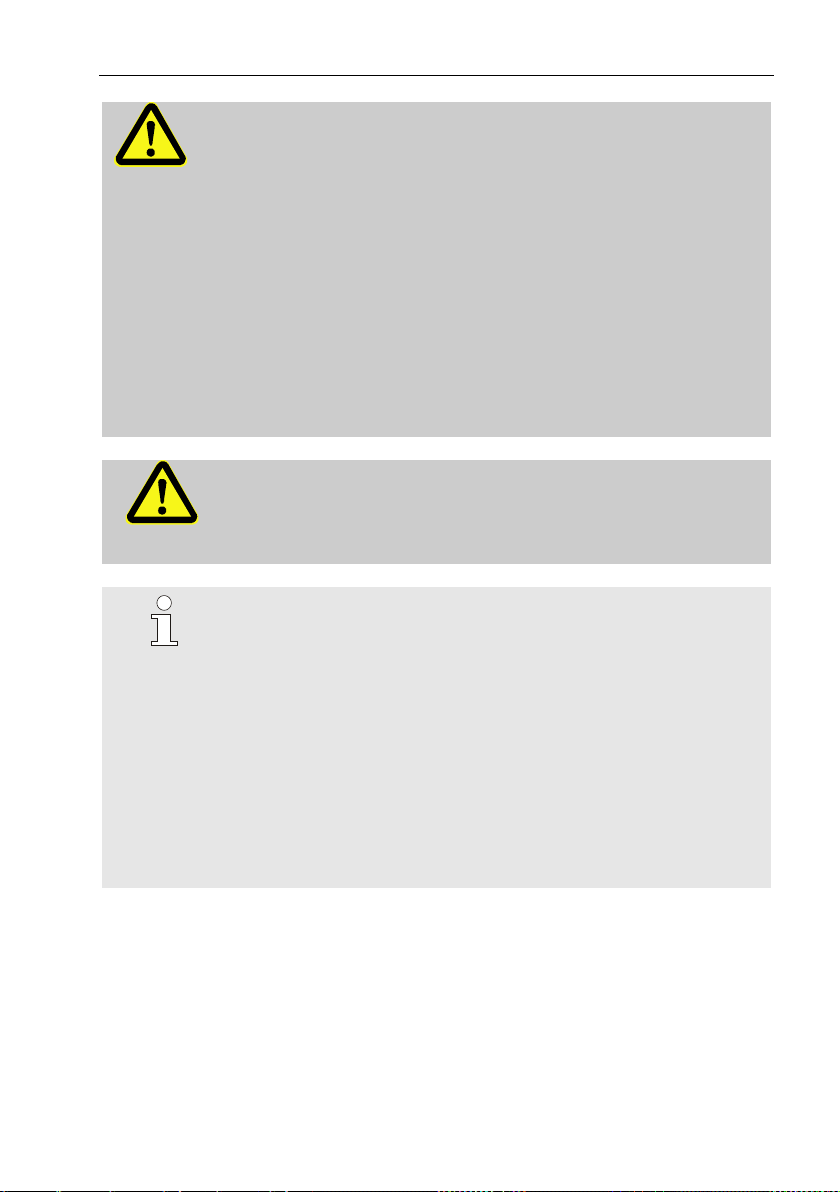
3.1.1 Dimensions
Page 22

22 Technical data
3.2 Power supply for EK280 without integrated power supply unit
3.2.1 Battery power supply for the basic device
Data
Value
Unit
Voltage
3.6 V General nominal capacity
16.5
Ah
Usable capacity
13.0
Ah
Minimum number of batteries required
2
units
Minimum operating life (at standard
measurement conditions)
5
years
The standard measurement conditions are defined as follows:
Data
Value
Measurement cycle
30 seconds
Mode input 1
Pulse input
Display active
60 minutes per month
Interface or modem active
30 minutes per month
Ambient temperature
-10 ... +50°C
3.2.2 Battery power supply for the integrated modem
Data
Value
Unit
Voltage
3.9 V General nominal capacity
16.0
Ah
3.2.3 External power supply for the basic device
Data
Value
Unit
Supply voltage
7.5 …8.5
V
Supply current, maximum
40
mA
Page 23

Technical data 23
3.3 Power supply for EK280 with integrated power supply unit
3.3.1 Battery power supply for the basic device
Batteries for switching to battery mode in the event of a power failure: see
chapter 3.2.1 "Battery power supply for the basic device"
3.3.2 External power supply
Data
Value
Unit
Supply voltage
115…230
V ~
Power consumption, maximum
10
W
3.3.3 Buffer batteries for the integrated modem
The buffer batteries can optionally be connected to the integrated power
supply unit to ensure that data continues to be transmitted, even in the
event of a power failure.
Data
Value
Unit
Voltage
3.6 V General nominal capacity
13.0
Ah
Usable capacity
8.0
Ah
Minimum number of batteries required
2
units
3.4 Power supply for the EK280 with Power over Ethernet (PoE)
If the EK280 is equipped with an Ethernet module and if the Ethernet
network (or a switch) provides the Power over Ethernet function, the EK280
can be supplied with power from the Ethernet module. An integrated power
supply is not required.
Data
Value
Unit
Supply voltage
36 V to 56 V
V DC
Page 24

24 Technical data
3.5 Pressure sensor
3.5.1 CT30 Type Pressure Sensor
Data
Value
Unit
External thread
M12 x 1.5
Usable thread length
approx. 10
mm
3.5.1.1 Absolute pressure ranges
Measuring range
Overload capacity
0.7 ... 2 bar abs.
18 bar abs.
0.8 ... 5 bar abs.
25 bar abs.
1.4 ... 7 bar abs.
25 bar abs.
2.0 ... 10 bar abs.
40 bar abs.
2.4 ... 12 bar abs.
40 bar abs.
4 ... 20 bar abs.
40 bar abs.
6 ... 30 bar abs.
60 bar abs.
8 ... 40 bar abs.
60 bar abs.
14 ... 70 bar abs.
105 bar abs.
16 ... 80 bar abs.
105 bar abs.
These pressure sensors are available as both an external
and internal model.
Further details can be found under www.elsterinstromet.com or chapter "Assembly, Connection and
Putting into Operation".
3.5.1.2 Relative pressure ranges
Measuring range
Overload capacity
1.4 … 7 bar rel.
40 bar rel.
4 … 20 bar rel.
40 bar rel.
16 … 80 bar rel.
105 bar rel.
These pressure sensors are only available as an externally
connected model and can only be used as a second
pressure sensor for non-metrological measurements.
Further details can be found under www.elsterinstromet.com or chapter "Assembly, Connection and
Putting into Operation".
Page 25

Technical data 25
3.5.2 Pressure Sensor Type 17002
Data
Value
Unit
External thread (internal model)
M12 x 1.5
Usable thread length (internal model)
approx. 10
mm
Measuring range
Overload capacity
0.9 … 7 bar abs.
10 bar abs.
The pressure sensor is available as both an external and
internal model. Further details can be found under
www.elster-instromet.com or chapter "Assembly,
Connection and Putting into Operation".
3.6 Temperature sensor
Data
Value
Unit
Measuring range
-30 … +60
°C
Measurement uncertainty
max. ± 0.1
%
Installation length
50
mm
3.7 Digital inputs
3.7.1 LF pulse and signal inputs
The maximum counting frequency of the digital inputs can be adjusted
using the "enSuite" software. The limit values specified for frequency and
duration shall only apply if the so-called "software debounce" has been
switched off.
The software debounce is activated ex-works to suppress interference
pulses and therefore restrict safe readings to 2 Hz.
If the software debounce is parameterized to a frequency
higher than 2 Hz, then it may lead to counting errors
caused by electromagnetic interference under certain
circumstances.
Page 26

26 Technical data
Data
Value
Unit
Open-circuit voltage U
0
5.0 V Internal resistance R
I
1 MΩ
Short circuit current I
K
5 μA
Switch point "ON":
▪ Resistance Re
max.
100
kΩ
▪ Voltage Ue
max.
0.8
V
Switch point "OFF":
▪ Resistance Ra
min.
2
MΩ
▪ Voltage Ua
min.
3 V Pulse duration te
min.
62.5
ms
Pause duration ta
min.
62.5
ms
Counting frequency f
max.
10
Hz
Counting frequency f for input 3
max.
6
Hz
3.7.2 HF pulse inputs (high frequency)
High frequency pulse transducers can only be connected to inputs 1 and 2
(terminals DE1 and DE2) (see chapter 5.2.1.3).
Data
Value
Unit
Open-circuit voltage
7.5 ... 8.5
V
"High" switching level
max. 1.2
mA
"Low" switching level
min. 2.1
mA
Input frequency
max. 2500
Hz
3.7.3 Encoder input
An encoder can only be connected to input 1 (terminal DE1).
Data
Value
Unit
Encoder protocol
Namur, SCR
-
Page 27

Technical data 27
3.8 Digital outputs
The digital outputs DA2 and DA3 can be configured as low or high
frequency pulse or signal outputs.
The digital outputs DA1 and DA4 can exclusively be configured as low
frequency pulse or signal outputs.
3.8.1 Nominal data
Data
Value
Unit
Maximum switching voltage
30
V DC
Maximum switching current
100
mA DC
Maximum voltage drop
1 V Maximum residual current
0.001
mA
3.8.2 LF pulse or signal outputs
Data
Value
Unit
Pulse duration
min.
125
ms
Pause duration
min.
125
ms
Output frequency
max.
4
Hz
3.8.3 HF pulse outputs
The use of outputs as high frequency output is only possible if an external
power supply has been connected (see chapter 5.2.5).
Only outputs 2 and 3 (terminals DA2 and DA3) can be used as high
frequency output.
Data
Value
Unit
Output frequency
max. 1000
Hz
If the HF output is fed via a FE260, the maximum output
frequency is limited to 500 Hz (depending on the
configuration of the outputs).
Page 28

28 Technical data
3.9 Interfaces
3.9.1 Serial optical interface
Data
Value
Unit
Baud rate
9600
Bd
Format
1 start bit, 1 parity bit, 1 stop bit
The baud rate of the serial optical interface is adjustable to
19200 Bd. However, the function with this baud rate depends
among others also from the optical read out head and
therefore cannot be guaranteed.
3.9.2 Serial electrical interface
Data
Value
Adjustable types
RS232 or RS485
3.9.2.1 Technical Data of the RS485 Interface
Data
Value
Operating modes
RS485 2-wire (half-duplex)
RS485 4-wire (full-duplex)
Termination
Do not use a termination resistor at any
device connected
Maximal data transfer rate
19.200 Baud
Number of devices
connected to the bus
max. 16 unit loads1
Power consumption at the input2:
- 6 unit loads (RS485, not electr. insulated)
- 3 unit loads (RS485, electrically
insulated)
3.9.3 Integrated modem
Data
Value
Unit
Modem type
2G: GSM / GPRS
3G: GSM / GPRS / UMTS
Frequency bands
2G: 850 /900 /1800 /1900
3G: 850 /900 /1800 /1900 /2100
MHz
1
Unit Load: Standard RS-485 receiver with an input resistance = 12kOhm
2
For details on connecting the RS485 interface, see Application manual.
Page 29
Technical data 29
3.9.4 Ethernet adapter
Data
Value
Unit
Type
100
Mbit
Supply
Internal mains-supply or PoE
Functions
TCP-IP Client/Server, FTP
3.10 Measurement conditions
3.10.1 Environment
Data
Value
Unit
Temperature range
-25…+55
°C
Relative humidity, max.
93
%
3.11 Labelling
The EK280 is approved as a volume corrector as per the Measuring
Instruments Directive (MID). The label is placed on the front panel of the
device (see Construction and Function chapter).
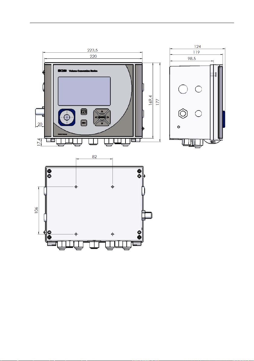
3.11.1 Type label3 of the volume corrector
The type label of the EK280 relating to its function as a volume corrector,
contains the following information:
Fig. 1
1 Type designation
2 CE marking
3 Metrology marking
4 Number of the EC type
examination
5 Measurement accuracy data
6 Reference to EN 12405-1
7 IP protection class data
8 Serial number
9 Year of construction
10 Ambient temperature range
3
The identification plate may contain other information depending on the design or the country of destination.
EK280
Year: 2011
Serialno.: 1234567
M 11 0102
MPE at ref. conditions 0,5%
IP65 EN12405-1
Ta: -25°C ... +55°C
EC type-examination number:
T10339
1
2
4 5 9 6 3
8
7
10
Page 30
30 Technical data
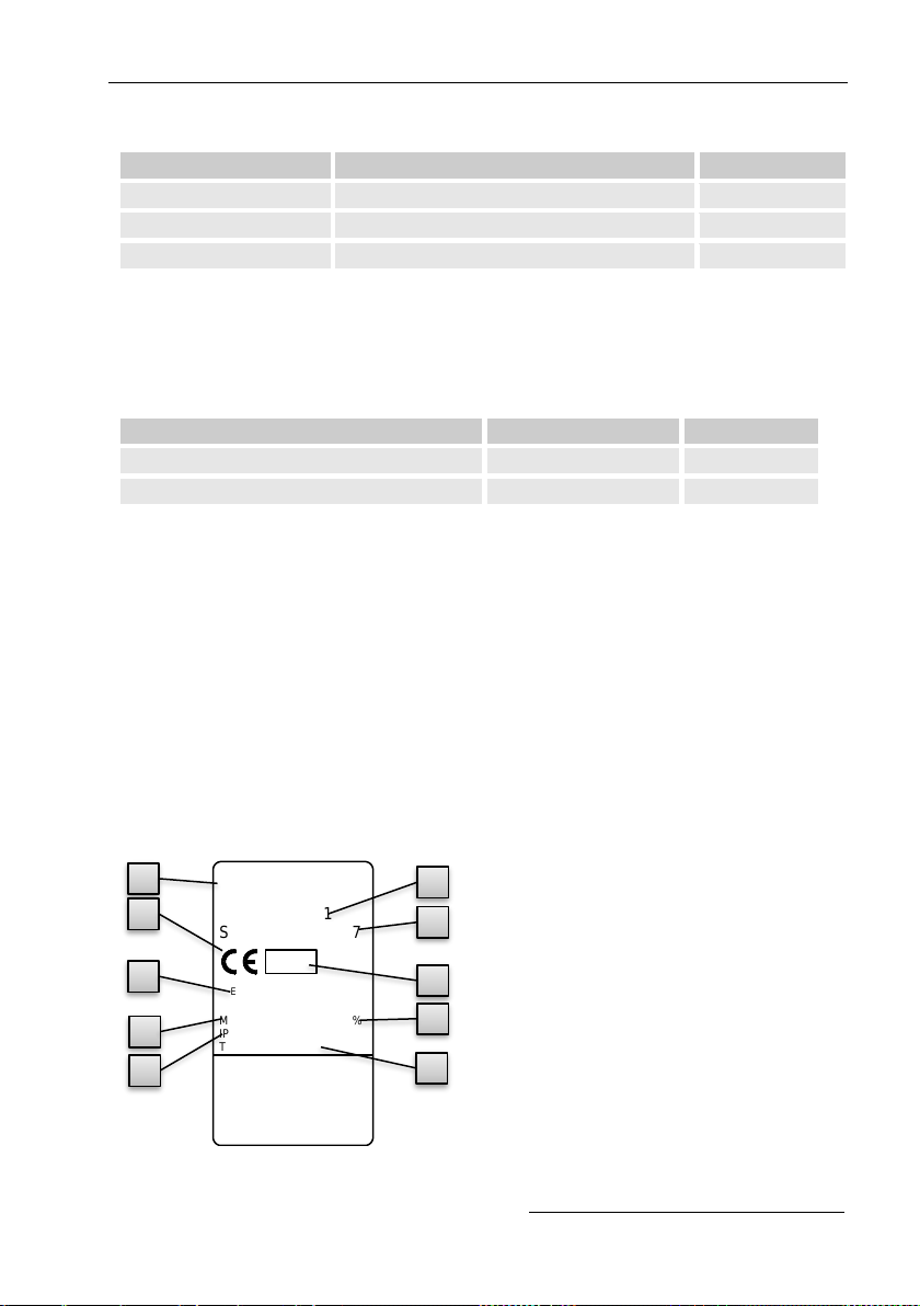
3.11.2 ATEX marking
The plate for the "Ex" marking of the EK280 is located on the top panel of
the device housing.
3.11.2.1 Zone 0, 1 (without integrated power supply unit)
Fig. 2
1 Manufacturer and address
2 Ex marking
3 Permissible ambient temperature
range
4 Identification number
5 Type designation of the device
6 Temperature class data
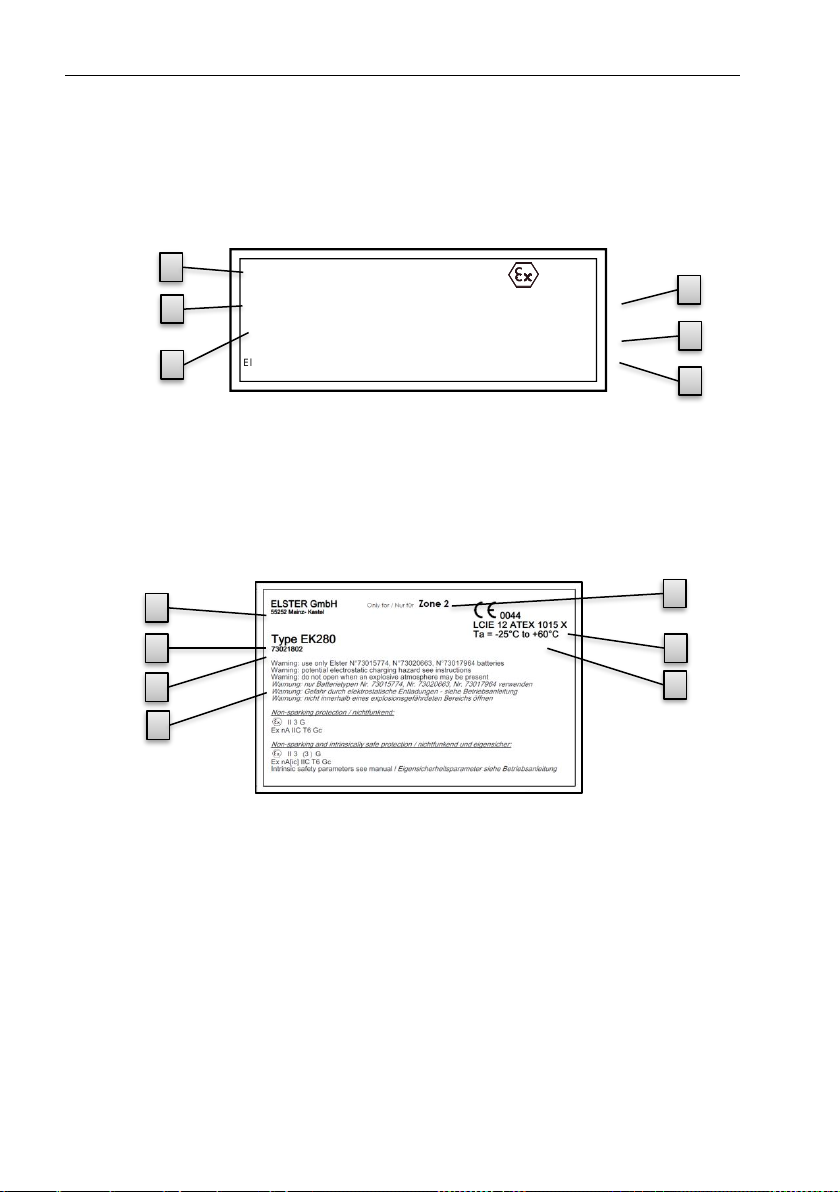
3.11.2.2 Zone 2 (with integrated power supply unit)
Fig. 3
1 Manufacturer and address
2 Ex marking
3 Permissible ambient temperature
range
4 Identification number
5 Type designation of the device
6 Ex zone data
7 Warning notices
73021250
Type EK280
Electrical parameters and batteries
see EC Type examination certificate
ELSTER GmbH
55252 Mainz- Kastel
II 1 G
Ex ia IIB T4 or T3 Ga
LCIE 11 ATEX 3027 X
T amb: -40°C to +60°C
T3 with radio module
T4 without radio module
1
6 3 4
5
2
1
6 3 4
5
2
7
Page 31

Technical data 31
3.11.3 Device software identification
– Move the cursor using the arrow keys to the "Serv." register and to
the values "Vers" (device software version) and "Chk" (checksum) via
the following path:
Serv. Identification Volume Converter "Vers" or "Chk"
– The checksum "Chk" can be recalculated for verification purposes by
pressing the ENTER button.
Page 32
32 Construction and Function
4 Construction and Function
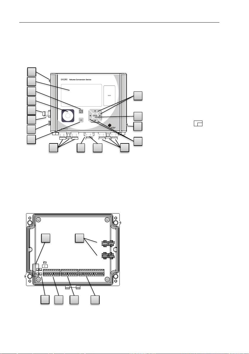
4.1 External view
Fig. 4
1 Display
2 Cable bushings for the
connection of additional
components
3 Optical interface
4 Escape button "ESC"
5 Enter button "ENTER"
6 Function key
7 Arrow keys , , ,
8 Pressure sensor
9 Cable bushing
Temperature sensor
10 Earth connection
11 Sealing eyelets
12 Outdoor plug (optional)
13 Cable bushing Aeria
4.2 Internal view
X14
X10
X11
X9 - +
X8
5210 1x4
5210 1x4
5210 1x4
5210 1x4
5210 1x4
5210 1x4
Fig. 5
1 Connections for temperature and
pressure sensors
2 Connections for counting and
signal inputs "DE1" to "DE6"
3 Connections for pulse and signal
outputs "DA1" to "DA4"
4 Connections for serial interfaces
5 Connections for external power
supply "Uext"
6 Connections for batteries
Instromet
Identification
label
1
6
3
8 9 10 4 5 7 2 2 12
13
7
11
11
6
5
4
3
2
1
Page 33

Construction and Function 33
4.3 Short description
The volume conversion device EK280 is an explosion-protected electronic
device that takes the volume of gas determined by an external meter at
measurement conditions to calculate the volume at base conditions and
therefore the energy portion of the respective gas volume.
Furthermore, the gas flow of a pipeline can be monitored, recorded and
transmitted by means of the recording function, the signal inputs and
outputs, as well as the serial and optical data interfaces of the device.
Recording the necessary state variables for this purpose takes place via an
externally or internally connected pressure sensor as well as a temperature
sensor. An alphanumeric display and a keyboard on the front panel of the
device serve as the control elements for the EK280.
4.4 Connections
The EK280 volume corrector can be connected to:
– Four batteries
– An external power supply
The following can be used to monitor and record the calculated data and to
transmit data and program functions:
– Six counting and signal inputs DE1, DE2, DE3, DE4, DE5, DE6
– Four pulse and signal outputs DA1, DA2, DA3, DA4
– Serial data interface
– Optical data interface
Further details on the connection possibilities for the EK280
and the available equipment versions can be found in the
"Technical Data" chapter and in chapter
"Assembly, Connection and Putting into Operation".
Page 34

34 Assembly, Connection and Putting into Operation
5 Assembly, Connection and Putting into
Operation
5.1 Assembly
DANGER!
Using the wrong model presents a risk of explosion!
The EK280 is available in different models for use in zones
1 and 2.
The model designed for zone 2 should not be used in zone 0, 1 as this
presents a risk of explosion!
Therefore:
– Before installing the device in zone 0, 1, please check that the EK280
is suitable for use in zone 0, 1.
– The EK280 should only be operated in zone 0, 1, if category "II 1 G"
or "II 2 G" have been marked on the ATEX label.
– If category "II 3 G" has been marked on the ATEX label, the EK280
should not be used in zone 0, 1, but only in zone 2.
– The ATEX label is located on the top panel of the EK280 housing.
The following solely applies for the EK280 model with integrated
power supply unit (ATEX category "II 3 G" for use in zone 2):
WARNING!
– Do not open when an explosive atmosphere may be
present!
– Electrostatic hazard: Do not rub!
The EK280 can either be mounted on a gas meter, on a
pipeline, or on a wall.
Should problems arise during assembly, e.g. with regard to
the selection of suitable assembly tools, please contact our
customer service team (see "General" chapter).
Page 35

Assembly, Connection and Putting into Operation 35
5.1.1 Assembly on a gas meter
Mount the EK280 on a gas meter using a mounting bracket
(see Appendix) as well as the corresponding cylinder screws
and square nuts.
Fig. 6
1. Using two M5 x 10 mm (Fig. 6: 4 )
cylinder screws, attach the
mounting bracket (Fig. 6: 6 ) to the
EK280 (Fig. 6: 1 ).
2. Tighten the cylinder screws so that
the bracket is sitting in a fixed
position.
3. Attach the mounting bracket using
two square nuts M5 (Fig. 6: 7 ) and
two M5 x 10 mm (Fig. 6: 5 )
cylinder screws at the back of the
meter head (Fig. 6: 8 ).
4. Tighten the cylinder screws so that
the device is in a fixed position and
cannot fall down.
5.1.2 Assembly on a pipeline
Mount the EK280 to a pipeline using an A2 universal
bracket with a pipe clamp (see Appendix) as well as
corresponding cylinder screws.
Fig. 7
1. Using two M5 x 10 mm (Fig. 7:
i1i) cylinder screws, insert the
A2 universal bracket in the
boreholes provided (Fig. 7: i3 )
on the EK280 (Fig. 7: i2 ).
2. Tighten the cylinder screws so
that the bracket is sitting in a
fixed position.
3. The A2 universal bracket (Fig. 7:
i3 ) and the device (Fig. 7: i2 )
should be fastened to the
pipeline (Fig. 7: i5 ) using the
pipe clamp (Fig. 7: i4 )
4. The device should be mounted on the pipeline in such a way that it is in
a fixed position and cannot fall down.
1
4
6 5 7
8
2
3
1 4 5
Page 36

36 Assembly, Connection and Putting into Operation
5.1.3 Assembly on a wall
Fig. 8
1. Bore four holes in the
positions marked on the wall
(see dimensions in
Fig. 8).
2. Select wall plugs which
correspond to the size of the
screws and insert these in the
boreholes in the wall.
3. To fasten the EK280, four
M5 x 40 mm wood screws
should be used for wall
assembly.
5.1.4 Three-way valve
When mounting the pressure sensor, a three-way valve is usually
incorporated in order to test the pressure sensor in an installed condition or
to exchange a faulty sensor without switching off the entire gas pipeline.
The three-way valve available from Elster is constructed as follows:
Fig. 9
i1 : From the meter: From the pressure
connection of the gas meter.
For diaphragm gas meters, this takes
place on the input side of the meter.
i2 : To the VC: For the connection of the
pressure sensor to the volume
corrector.
i3 : Test connection: Possible to take the
test pressure or to assert external
pressure on the pressure sensor of
the volume corrector.
When mounting the three-way valve, it must be ensured that
the position of the control lever with the corresponding outlets
is checked as the lever can be removed and may be mounted
the wrong way round.
Prüfen mit
Betriebsdruck
Betriebs-
stellung
Prüfen mit
Frmddruck
Absperrung
45° Stellung
1 2 3
Page 37

Assembly, Connection and Putting into Operation 37
The pipeline from the pressure sensor to the meter must be
laid at an angle in order to ensure that water does not damage
the pressure sensor or affect the measurement accuracy.
5.2 Connection
The EK280 is available as both a calibrated and noncalibrated device. Information regarding additional equipment
versions of the EK280 can be found under www.elsterinstromet.com.
DANGER!
The connection of non-intrinsically-safe or nonassociated equipment presents a risk of explosion!
The operation of the EK280 in zones 1 and 2 and the
connection of non-intrinsically-safe equipment which exceeds
those conditions and limit values specified in the declaration
of conformity, presents a risk of explosion.
Therefore:
– The device should only be connected inside zones 1 and
2 and only to certified associated equipment as per the
ATEX Product Directive 94/9/EC.
– Only devices with intrinsically-safe circuits and electrical
data that corresponds to those requirements stipulated in
the declaration of conformity for the EK280 (see
Appendix), should be connected.
WARNING!
Risk caused by incorrect connection of the device!
The device should solely be connected by a gas specialist (see "Safety"
chapter). Incorrect connections may lead to life-threatening situations or
significant material damage.
Therefore:
– The calibrated device should only be connected by a gas specialist.
– The same specialist should also be consulted if subsequent changes
to location arise.
– Please refrain from unauthorized connections and relocations of the
device.
Page 38

38 Assembly, Connection and Putting into Operation
– When connecting the EK280 and putting it into operation, the
guidelines of the corresponding DIN EN 60079-0 and DIN EN 6007914 standards should be observed.
– The wiring of the connections should be professionally carried out by
a gas specialist or a calibration officer.
– Active outputs cannot be switched.
– Connect unused cable glands as per DIN EN 60079-14 with the help
of a plug or a suitable screw cap.
– Insulate any unused wire (e.g., in multicore cables) at the end by
appropriate termination means. (see "Technische Regel für Betriebssicherheit (TRBS)")
In order to program the device and perform further applications, and in
addition to the components specified in this chapter, you can also connect
an external power supply to the other connections as well as the serial and
optical interface of the EK280 (see "Construction and Function" chapter).
Further details can be found under www.elster-instromet.com.
The connections described below should only be sealed by
a calibration officer. If the EK280 is used for operations
which are not subject to calibration regulations, the seals on
the respective connections can be omitted.
5.2.1 Connecting the gas meter
In order to measure the gas volume, a gas meter with a low or high
frequency pulse transducer or encoder can be connected to the digital input
"DE1" of the EK280.
Fig. 10
The pulse transducer or encoder of
the gas meter will be connected to
the "DE1" terminal
( 1 ) of the EK280.
Further details and special features
regarding the use of the pulse
transducer and encoder are
described in the following subchapters.
The cable core diameter for the connection to the EK280
inputs is 0.33 … 2.5 mm
2
.
1
Page 39

Assembly, Connection and Putting into Operation 39
5.2.1.1 Connection to a low frequency pulse transducer
1. Connect the pulse output of the gas meter to the "DE1" terminal ( 1 in
Fig. 10, page 38) of the EK280.
The polarity can be freely selected (the symbols "+" and "-" on the
terminals are used for the connection of other pulse transducers or
encoders).
2. Adjust the measurement parameters, e.g. the cp value (pulse constant),
as described in chapter 5.2.1.1.
5.2.1.2 Connection to an encoder
1. Connect the encoder of the gas meter to the "DE1" terminal ( 1 in Fig.
10, page 38) of the EK280.
The polarity should be taken into consideration, i.e. connect the "+" of
the encoder to the "DE1 +" terminal and "-" to the "DE1 -" terminal
respectively.
2. Adjust the measurement parameters, e.g. the encoder type, as
described in chapter 5.3.1.3.
5.2.1.3 Connection to a high frequency pulse transducer
The EK280 can only count the pulses of a high frequency
pulse transducer if there is an external power supply - not
when in battery mode.
In order to ensure an uninterrupted measurement of the gas volume, the
EK280 can be configured in such a way that the device automatically
switches to a low frequency pulse transducer in the event of a failure of the
external power supply; see chapter 5.2.1.4.
If you would like to use the automatic switching function of the
pulse transducer, please proceed as per chapter5.2.1.4 !
1. Connect the high frequency pulse output of the gas meter to the "DE1"
terminal ( 1 in Fig. 10, page 38) of the EK280.
The polarity should be taken into consideration, i.e. connect the "+" of
the pulse transducer with the "DE1 +" terminal and "-" with the "DE1 -"
terminal respectively.
2. Adjust the measurement parameters, e.g. the cp value (pulse constant),
as described in chapter 5.3.1.4.
Page 40

40 Assembly, Connection and Putting into Operation
5.2.1.4 Automatic switchover of the pulse transducer
The EK280 should be configured as described in order to ensure an
uninterrupted measurement of the gas volume when using a high
frequency pulse transducer.
If the power supply is in a functioning order, the volumes and flows (Vb,
Vm, Qb, Qm) will be measured with the high frequency pulse transducer. In
the event of a failure of the external power supply, the EK280 will
automatically switch to the low frequency pulse transducer.
Fig. 11
1. Connect the low frequency pulse
transducer of the gas meter to the
"DE1" terminal (1 ) of the EK280.
2. Connect the high frequency pulse
transducer of the gas meter to the
"DE2" terminal (2 ) of the EK280.
3. Adjust the measurement
parameters, e.g. the cp value
(pulse constant), as described in
chapter 5.3.1.5.
5.2.2 Sealing the input terminals
After connecting to the gas meter as per chapter 5.2.1, the input terminal
"DE1" must be sealed for official calibration measurements.
For this purpose, terminal covers are provided in the bag of accessories. If
required, these should be screwed over the connected terminals and an
adhesive seal should then be bonded to the fastening screw (see chapter
5.3.2).
5.2.3 Connecting the temperature sensor
Any national requirements must be observed when
connecting the temperature sensor.
The requirements of the PTB Testing Instructions, Volume
20, Electronic volume conversion device for gas, Chapter 5,
shall apply to Germany.
Before connecting, the temperature sensor should be
lubricated with heat transfer fluid in order to enhance its
functionality.
1
2
Page 41

Assembly, Connection and Putting into Operation 41
5.2.3.1 Connection to a standard temperature sensor pocket
Fig. 12
1. Insert the temperature sensor
Pt500 4 into the temperature
sensor pocket 5 (see Appendix).
2. Fasten the temperature sensor
using the capstan screw 2 and
screw connections provided 6 .
3. Have a calibration officer seal the
temperature sensor using the
sealing sleeve 1 and the wire
seal 3 as per Fig. 12.
5.2.3.2 Connection to an older temperature sensor pocket
Fig. 13
1. Insert the temperature sensor Pt500
5 into the temperature sensor
pocket 6 (see Appendix).
2. Use the adapter 2 to seal the
connection (see Appendix).
3. Fasten the temperature sensor
using the capstan screw 3 and the
screw connections 8 provided.
4. Have a calibration officer seal the
temperature sensor using the
sealing sleeve 1 and the wire seal
4 , 7 .
1
2
3
4
5
6
1 2 3
4
5
6 7 8
Page 42

42 Assembly, Connection and Putting into Operation
5.2.4 Connecting the pressure pipe
Any national requirements must be observed when
connecting the pressure pipes.
The requirements of the PTB Testing Instructions, Volume
20, Electronic volume conversion device for gas, Chapter 5,
shall apply to Germany.
Efforts must be made to ensure the pipes are installed
downwards.
5.2.4.1 Connection to an internal pressure sensor
Fig. 14
1. Connect the pressure
connection to the internal
pressure sensor connection 1
using the union nut and the
sealing insert 4 .
2. Have a calibration officer seal
the connection with the
sealing sleeve 2 and a wire
seal 3 .
5.2.4.2 Connection to an external pressure sensor
Fig. 15
1. Connect the pressure
connection 7 to the external
pressure sensor 6 .
2. Have a calibration officer seal
2 the connection with a
sealing sleeve 1 .
2 1 3
4
4
3
2
1
5
6
7
Page 43

Assembly, Connection and Putting into Operation 43
5.2.5 Connecting the power supply
5.2.5.1 Power supply for the EK280 without integrated power supply unit
DANGER!
The connection of non-associated equipment presents a
risk of explosion!
Operating the EK280 in zone 0, 1 and connecting devices
which are not certified as "associated equipment" present a
risk of explosion.
Therefore:
– When using the EK280 in zone 0, 1, it should only be
connected to certified associated equipment as per the
ATEX Product Directive 94/9/EC.
– The EK280 should only be connected to the intrinsically-
safe circuits of associated equipment whose electrical
data corresponds to those requirements stipulated in the
declaration of conformity for the EK280 (see Appendix).
For the external power supply of the EK280 (model without in-built power
supply unit), the electrical data should be adhered to as per chapters 9.3
and 3.2.3.
The extended function unit "FE260" from Elster can also be used as a
power supply unit, for example.
Fig. 16
Connect the power supply to the
"Uext" terminal ( 1 ) of the EK280.
The polarity should be taken into
consideration, i.e. connect the "+" of
the power supply unit to the "Uext +"
terminal and "-" to "Uext -".
1
Page 44

44 Assembly, Connection and Putting into Operation
5.2.5.2 Power supply for the EK280 with integrated power supply unit
DANGER!
Danger to life from electrical current!
Touching live parts poses an imminent danger to life.
Therefore:
– Works on the electrical components of the device, i.e. the connection
of the power supply unit, should solely be carried out by qualified
electricians.
– When performing all works to the electrical system, switch off the
power, secure it against an accidental restart and check to ensure
that the voltage has been cut.
– Keep live parts away from moisture. This could lead to a short-circuit.
The power supply unit to connect the 115…230 V~ power supply, is in-built
into the base of the EK280.
Fig. 17
1. Switch off the supply voltage and
secure it against an accidental
restart!
2. Connect the 115…230 V~ supply
voltage to the "J2" terminal block
( 1 ) of the EK280.
The cable core diameter for the connection to the
integrated power supply unit is 0.2 … 1.5 mm
2
.
DANGER!
Danger to life from electrical current!
Connect protective ground wire of mains-supply to screw
terminal J2, connection E!
1
Page 45

Assembly, Connection and Putting into Operation 45
5.2.6 Connect outputs of the EK280
The cable core diameter for the connection to the EK280
outputs is 0.33 … 2.5 mm
2
.
Different downstream devices can be connected to the
digital outputs of the EK280. The outputs are preconfigured
for this purpose (see chapter 5.3.1.13).
Fig. 18
1. Connect the downstream device to the
corresponding digital outputs (terminals
"DA1" to "DA4") of the EK280 (p. Fig.
18).
2. Terminal covers are provided in the bag
of accessories to seal the output
terminals. If required, these should be
screwed over the connected terminals
and a seal should then be bonded to the
fastening screw (see chapter 5.3.2).
3. If necessary, adjust the cp value (pulse contact) for the pulse outputs as
described in chapter 5.3.1.13.
5.2.6.1 Electrical insulation of the outputs
In standard cases, all negative poles of the outputs are electrically
connected to the motherboard.
For special applications, i.e. switching a positive pole, each output can be
electrically separated from the motherboard and from the other outputs.
CAUTION!
Reduced battery life
Activating the electrical insulation of outputs reduces the
battery life when in battery mode!
It is then impossible to give a reliable prediction of the
remaining battery life.
Page 46

46 Assembly, Connection and Putting into Operation
An electrically-insulated output only requires electricity if the
output is active (switched-on). You can therefore minimize the
negative influence of an electrically-insulated output on the
battery life by setting the pulse duration to the lowest possible
value when using it as a pulse output.
The configuration software "enSuite" can be used for this
purpose.
The electrical insulation of the outputs is not an approved
electrical isolation in accordance with ATEX. An approved Exisolator is required when using the device in Ex zone 0, 1.
In order to activate the electrical insulation of an output, please move the
switch lever behind the corresponding output terminal away from the
terminal:
Fig. 19
Electrical insulation switch
Output "DA3" is electrically insulated
(the switch slider is on top)
Outputs "DA1", "DA2" and "DA4" are not
electrically insulated (the switch sliders are
underneath)
5.2.7 Earthing the EK280 housing
The housing of the EK280 must always be earthed.
A M6 screw is provided for this on the left-hand side of the
housing.
1. The earth-cable must have a minimum diameter of 4mm2.
2. Use the cable to connect the screw on the left-hand side of the housing
with the equipotential bonding strip.
Page 47

Assembly, Connection and Putting into Operation 47
5.2.8 Earthing the cable connections of the EK280
All cables firmly connected to the EK280 have a shield. This
is connected to the cable glands of the EK280 in order to
prevent electromagnetic interference.
Only shielded cables should be used for new connections.
The cable shield should be completely earthed on both
sides. For this purpose, the EK280 is equipped with special
cable glands.
5.2.9 Additional measures for installation in zone 2
For the installation of the EK280 model with an integrated
power supply unit (ATEX category "II 3 G") in zone 2, the
following additional measures are necessary:
– A cable-tie must be mounted on each cable inside the
housing as strain relief.
Place the cable-tie right beside the cable gland.
– All cable glands have to be fastened with minimum
- 6 Nm for metal glands
- 1.5 Nm for plastic glands
– Use only cables with the following outside-diameters for
installation of the different cable gland types
M12, metal: 4.5 mm
M16 and M20, metal: 8 mm
M16, plastic: 8 mm
The ATEX category "II 1 G" models of the EK280 (without in-built power
supply unit) should be installed in both zones 1 and 2 without these
additional measures.
Page 48

48 Assembly, Connection and Putting into Operation
5.3 Putting into operation
5.3.1 Configuration of measurement parameters
If the EK280 is subject to calibration regulations, the works
described below should only be performed by legally
authorized individuals.
The necessary measurement parameters can be adjusted using the free
configuration program "enSuite", which is available under www.elsterinstromet.com.
If the program is not available, the configuration can also be carried out
using the keyboard as described below.
Before adjusting the measurement parameters via the
keyboard, please read chapter 6 to learn how the device is
operated.
5.3.1.1 Opening the calibration lock
The calibration lock is located at the back of the housing cover in the form
of a button, and this can be secured by means of an adhesive label. This
button must be pressed in order to adjust the values and parameters
protected by configuration regulations.
X14
X10
X11
X9 - +
X8
5210 1x4
5210 1x4
5210 1x4
5210 1x4
5210 1x4
5210 1x4
Position of the button to
open the calibration lock.
Page 49

Assembly, Connection and Putting into Operation 49
5.3.1.2 Adjusting the parameters for the low frequency pulse
transducer of the gas meter
If a low frequency pulse transducer is connected as per 5.2.1.1, adjust the
input mode and the cp value as follows:
1. Adjusting the input mode:
– Move the cursor to the "Serv." register and to the input mode "Md.I1"
via the following path:
Serv. Inputs Input 1 Md.I1
– Press the ENTER button. The set value will start to flash.
– Press one of the arrow keys or until the text "Pulse input" starts
to flash.
– Press the ENTER button to confirm the set value. The input value
can be deleted by pressing the ESC button.
2. Adjusting the cp value (pulse constant):
– Move the cursor to the cp value "cp.I1" via the same path.
– Press the ENTER button. The value will start to flash.
– Move the cursor using the arrow keys or to the digits and
change these using the arrow keys or .
– Press the ENTER button to confirm the set value. The input value
can be deleted by pressing the ESC button.
5.3.1.3 Activating encoder mode
If an encoder is connected as per 5.2.1.2, the encoder mode is activated as
follows:
Start the "Auto Detect" function using the keyboard of the EK280 as
follows:
– Move the cursor to the "Serv." register and to the value "Md.I1" (input
mode) via the following path:
Serv. Inputs Input 1 Md.I1
– Press the ENTER button. The set value will start to flash.
– Press one of the arrow keys or until the text "Auto-Encoder"
starts to flash.
– Press the ENTER button to confirm the set value. The input value
can be deleted by pressing the ESC button.
– Wait until "Auto-Encoder" is replaced by another value. This may take
up to one minute as the EK280 consecutively activates and tests all
known encoder protocols.
Page 50

50 Assembly, Connection and Putting into Operation
– Once the EK280 has successfully detected the encoder, it will display
the meter reading of the gas meter with the description "Vo":
Serv. Volume Inputs Input 1 Vo
Unlike the "Auto Detect" function, you can also select the connected
encoder type directly under "Md.I1".
Serv. Volume Inputs Input 1 Md.I1
The following encoder types can be selected:
Md.I1
Meaning
Enc.Namur a
Encoder Namur a protocol
Enc.SCR EDIS
Encoder SCR EDIS95
Enc.SCR OBIS
Encoder SCR OBIS05
Enc.Nam. a-b
Encoder Namur a and b protocol
5.3.1.4 Adjusting the parameters for the high frequency pulse
transducer of the gas meter
If a high frequency pulse transducer is connected as per 5.2.1.3, the input
mode and the cp value should be adjusted as follows:
1. Adjusting the input mode:
– Move the cursor to the "Serv." register and to the input mode "Md.I1"
via the following path:
Serv. Inputs Input 1 Md.i1
– Press the ENTER button. The set value will start to flash.
– Press one of the arrow keys or until the text "HF pulses" starts to
flash.
– Press the ENTER button to confirm the set value. The input value
can be deleted by pressing the ESC button.
2. Adjusting the cp value (pulse constant):
– Move the cursor to the cp value "cp.I1" via the same path.
– Press the ENTER button. The value will start to flash.
– Move the cursor using the arrow keys or to the digits and
change these using the arrow keys or .
– Press the ENTER button to confirm the set value. The input value
can be deleted by pressing the ESC button.
5.3.1.5 Adjusting the automatic switchover of the pulse transducer
Page 51

Assembly, Connection and Putting into Operation 51
If the automatic switchover of the pulse transducer (see chapter 5.2.1.4) is
used, adjust the necessary parameters as follows:
1. Adjusting the automatic switchover:
– Move the cursor to the "Serv." register and to the value "Sc.Vm"
(sources for the volume at measurement conditions) via the following
path:
Serv. Volume Actual volume Parameter settings Sc.Vm
– Press the ENTER button. The set value will start to flash.
– Press one of the arrow keys or until the text "Input 2" starts to
flash.
– Press the ENTER button to confirm the set value. The input value
can be deleted by pressing the ESC button.
2. Adjust the input mode of the high frequency pulse transducer:
– Press the button to display "Md.I2".
– Press the ENTER button. The set value will start to flash.
– Press one of the arrow keys or until the text "HF pulses" starts to
flash.
– Press the ENTER button to confirm the set value. The input value
can be deleted by pressing the ESC button.
3. Adjust the cp value of the high frequency pulse transducer:
– Press the button to display "cp.I2".
– Press the ENTER button. The set value will start to flash.
– Move the cursor using the arrow keys or to the digits and
change these using the arrow keys or to the cp value of the
pulse transducer connected to input 2.
– Press the ENTER button to confirm the set value. The input value
can be deleted by pressing the ESC button.
4. Adjust the parameters for the low frequency pulse transducer:
– Adjust the parameters for the low frequency pulse transducer on
input 1 as described in chapter 5.3.1.2.
Page 52

52 Assembly, Connection and Putting into Operation
5.3.1.6 Setting the volume at measurement conditions
In order to control the recording of the volume at measurement conditions,
the EK280 meter can be set once to the same value as the gas meter if the
administrator lock is open. It is always possible to set the volume if the
calibration lock is open:
– Open the administrator lock or the calibration lock
– Move the cursor to the „Serv.“ tab and go to the value „VmA“
(adjustable volume at measurement conditions) via the following
path:
Serv. Volume Actual volume Synchronization Vm VmA
– Press the ENTER key. One of the value digits flashes.
– Move the cursor using the arrow keys or to the digits and
change these using the arrow keys or .
– Once you have changed all of the digits, press the ENTER key in
order to confirm your entry. The entry can be cancelled by pressing
the ESC key.
– In order to accept the set value, move the cursor to the value „Store“
– Press the ENTER key. „0“ flashes.
– Change the value using the arrow keys or to „1“
– Once you have changed the value, press the ENTER key in order to
confirm your entry. The entry can be cancelled by pressing the ESC
key. „Vm“ is assumed for „VmA“.
If, when the administrator lock is open, the assumption of
„VmA" for „Vm" is rejected with the message –13--, then this
process has already been carried out once.
Other changes are possible if the calibration lock is open or, if
the administrator lock is open, after deleting the change
information for comparison of „Vm" with the gas meter (see
chapter 5.3.1.7).
Page 53

Assembly, Connection and Putting into Operation 53
5.3.1.7 Deleting change information for comparison of Vm with the
gas meter
In order to allow the volume at measurement conditions to be reset if the
administrator lock is open, the change information for comparison of "Vm"
with the gas meter must be deleted:
– Open the calibration lock
– Move the cursor to the „Serv.“ tab and go to the value „Clear“
(deleting change information) via the following path:
Serv. Volume Actual volume Synchronization Vm Clear
– Press the ENTER key „0“ flashes.
– Change the value using the arrow keys or to „1“
– Once you have changed the value, press the ENTER key in order to
confirm your entry. The entry can be cancelled by pressing the ESC
key. „TimeX“ (time stamp of comparison), „Vm_o“ (Vm old value),
„Vm_n“ (Vm new value) are set to default value.
5.3.1.8 Setting the volume at base conditions
For the EK280 volume conversion device, there is the option available
when commissioning the device to set the volume at base conditions meter
once if the administrator lock is open. It is always possible to set the
volume if the calibration lock is open:
– Open the administrator lock or the calibration lock
– Move the cursor to the „Serv.“ tab and go to the value „VbA“
(adjustable volume at base conditions meter) via the following path:
Serv. Volume Standard volume Synchronization Vb VbA
– Press the ENTER key One of the value digits flashes.
– Move the cursor using the arrow keys or to the digits and
change these using the arrow keys or .
– Once you have changed all of the digits, press the ENTER key in
order to confirm your entry. The entry can be cancelled by pressing
the ESC key.
– In order to accept the set value, move the cursor to the value „Store“
– Press the ENTER key. „0“ flashes.
– Change the value using the arrow keys or to „1“
– Once you have changed the value, press the ENTER key in order to
confirm your entry. The entry can be cancelled by pressing the ESC
key. „Vb“ is assumed for „VbA“.
Page 54

54 Assembly, Connection and Putting into Operation
If, when the administrator lock is open, the assumption of
„VbA“ for „Vb“is rejected with the message –13--, then this
process has already been carried out once.
Other changes are possible if the calibration lock is open or, if
the administrator lock is open, after deleting the change
information for comparison of „Vb“ (see chapter 5.3.1.9).
5.3.1.9 Deleting change information for comparison of Vb with the
gas meter
In order to allow the volume at base conditions to be reset if the
administrator lock is open, the change information for comparison of „Vb“
must be deleted:
– Open the calibration lock
– Move the cursor to the „Serv.“ tab and go to the value „Clear“
(deleting change information) via the following path:
Serv. Volume Standard volume Synchronization Vb
Clear
– Press the ENTER key. „0“ flashes.
– Change the value using the arrow keys or to „1“
– Once you have changed the value, press the ENTER key in order to
confirm your entry. The entry can be cancelled by pressing the ESC
key. „TimeX“ (time stamp of comparison), „Vb_o“ (Vb old value),
„Vb_n“ (Vb new value) are set to default values.
Page 55

Assembly, Connection and Putting into Operation 55
5.3.1.10 Adjust compressibility equation and gas analysis
– Move the cursor to the "Serv." register and to the value "Md.K"
(compressibility equation) via the following path:
Serv. Volume conversion Parameter settings Md.K
– Press the ENTER button. The set value will start to flash.
– Change the value using the arrow keys or . Adhere to the valid
legal provisions for the area of application.
Md.K
Meaning
fix value
No calculation of compressibility. The adjustable value
"K.F" will be used.
S-Gerg-88
Calculation of compressibility as per S-Gerg-88
AGA-NX19
Calculation of compressibility as per AGA-NX19
AGA-8 GC1
AGA8 Gross Characterization Method 1
AGA-8 GC2
AGA8 Gross Characterization Method 2
AGA-NX19-HW
AGA-NX19 according to Herning and Wolowsky
AGA-8 DC92
Calculation of compressibility as per AGA8 DC92
– Press the ENTER button to confirm the set value. The input value
can be deleted by pressing the ESC button.
– After selecting the compressibility equation, move the cursor along to
the gas analysis values (Ho.b, CO2 etc.) using the arrow keys or
.
– Change the values according to the gas used by confirming the input
by pressing the ENTER button or use the arrow keys or to go to
the digits and change these with the buttons or .
– Press the ENTER button to confirm the set value. The input value
can be deleted by pressing the ESC button.
The calorific value Ho,b applies to the basic conditions pbX,
TbX and reference combustion temperature +25°C.
pbX and TbX are adjustable under calibration lock.
5.3.1.11 Adjust alarm limits for gas pressure and temperature
measurement
Alarm limits are set to default values ex-factory. If a change becomes
necessary, please proceed as follows:
– Move the cursor to the "Serv." register and move to the alarm limit
values via the following paths:
Page 56

56 Assembly, Connection and Putting into Operation
Serv. Measured values Pressure Parameter settings pMin
and pMax
Serv. Measured values Temperature Parameter settings
TMin and TMax
– Press the ENTER button to confirm the input.
– Use the arrow keys or to go to the digits and change these with
the arrow keys or .
– Press the ENTER button to confirm the set value. The input value
can be deleted by pressing the ESC button.
5.3.1.12 Adjusting replacement values for gas pressure and gas
temperature
If the gas pressure or gas temperature cannot be measured due to a fault,
an adjustable replacement value (fixed value) will be used to calculate the
volume at base conditions. The volume calculated in this way will be
counted in the separate disturbance quantity meter "VbD".
The replacement values can be found under the following paths:
Serv. Measured values Pressure Parameter settings p.F
Serv. Measured values Temperature Parameter settings T.F
Changing the values generally takes place precisely as described in
chapter 5.3.1.12 for the alarm limit values.
5.3.1.13 Configuration of the outputs
The cp values (pulse constants) for the outputs can also be
configured using the enSuite software.
The following functions are preset ex-factory for the outputs:
Outputs
Function
Output 1
Pulse output for the total volume at base conditions "VbT"
(cp.O1 = 0.1)
Output 2
Pulse output for the total volume at measurement conditions
"VmT" (cp.O2 = 0.1)
Output 3
Status output for warnings (see chapter 8.2)
Output 4
Status output for alarms (see chapter 8.2)
The cp value of an output indicates how many pulses are emitted per cubic
meter. A cp value of 0.1 / m3 (0.1 pulses per m3) means, for example, that
one pulse is emitted per 10 m3.
Page 57

Assembly, Connection and Putting into Operation 57
To change the cp values for output 1 or output 2, move the cursor to the
"Serv." register and go to "cp.O1" (for output 1) or "cp.O2" (for output 2) via
the following path:
Serv. Outputs Output 1 cp.O1
or Serv. Outputs Output 2 cp.O2
– Press the ENTER button . The cp value will flash.
– Move the cursor using the arrow keys or to the digits and
change these using the arrow keys or .
– Press the ENTER button to confirm the set value. The input value
can be deleted by pressing the ESC button.
Aside from the settings described here, a range of other
functions can be configured for the outputs, e.g. high
frequency or time-synchronous pulses.
A complete description can be found in the EK280 Application
Manual that can be downloaded under www.elsterinstromet.com.
5.3.1.14 Setting the daylight saving time
– Move the cursor to the "Serv." register and to the "MdTim" value
(daylight saving mode) via the following path:
Serv. Date and Time MdTim
– Press the ENTER button. The set value will start to flash.
– Change the value using the arrow keys or :
MdTim
Meaning
CEST off
No switchover to daylight saving time
CEST autom.
Automatic switchover to daylight saving time
(CEST = Central European Summer Time)
CEST manual
The start and end of daylight saving time is
configured by the control center every year.
– Press the ENTER button to confirm the set value. The input value
can be deleted by pressing the ESC button.
Page 58

58 Assembly, Connection and Putting into Operation
5.3.1.15 Deleting the measurement archive
Deleting the archive is not absolutely necessary when putting
the device into operation.
– Move the cursor to the "Serv." register and to the "Clr.A" value (delete
measurement archive) via the following path:
Serv. Edit and delete Clr.A
All measurement archives (no logs) will be deleted.
In order to ensure that the archive is not accidentally deleted,
the serial number of the EK280 must be entered whilst the
calibration lock is open (the number is located on EK280
identification plate).
– Press the ENTER button. The value will start to flash.
– Move the cursor using the arrow keys or to the digits and enter
the serial number of the device using the arrow keys or .
– After you have entered the serial number of the device, press the
ENTER button to confirm the input. The input value can be deleted by
pressing the ESC button.
5.3.1.16 Deleting the certification data log
The log can only be deleted if the calibration lock is open.
– Move the cursor to the "Serv." register and to the value "ClCDL"
(delete certification data log) via the following path:
Serv. Change and Delete ClCDL
– Press the ENTER button. "0" will start to flash.
– Change the value to "1" with the arrow keys or .
– After you have entered the value, press the ENTER button to confirm
the input. The input value can be deleted by pressing the ESC button.
5.3.1.17 Closing and securing the calibration lock
After all settings subject to calibration regulations have been adjusted,
close the calibration lock in the same way that it was opened: Press the
buttons described in chapter 5.3.1.1 once again. The calibration switch is
secured with an adhesive label as described in chapter 5.3.2.2.
Page 59

Assembly, Connection and Putting into Operation 59
5.3.2 Sealing
5.3.2.1 External view
Fig. 20
1 Possible sealing point to
secure the identification
plate via adhesive seal.
2 Optional user lock: Seal
covers using wire seals
through sealing eyelets.
5.3.2.2 Internal view
Fig. 21
1 Sealing point to secure
the calibration switch.
2 Sealing points to secure
the circuit board cover
3 Sealing points to secure
the sensor covers for the
pressure and
temperature sensors.
4 Sealing points to secure
the terminal covers of the
inputs, outputs and
interfaces if necessary.
These sealing points ( 4 ) to secure the pulse inputs and pulse
outputs are subject to national regulations (cf. WELMEC 11.1,
chapter 2.7.1).
Depending on the legal situation in the respective country of
use, seals produced by legally authorized manufacturers or the
metering point operators, should be used.
If the devices are supplied with connected input and/or output
cables, seals will be provided with the manufacturing symbol as
standard. If necessary, these can be replaced in the area of
application as described above.
Instromet
EK280
Year: 2011
Serialno.: 1234567
M 11 0102
MPE at ref. conditions 0,5%
IP65 EN12405-1
EC type-examination number:
T10339
V1.3
1
2
2
4
3
2
1
Page 60

60 Assembly, Connection and Putting into Operation
Instromet
5.3.2.3 Sensors
Examples of how to seal the connected temperature and
pressure sensors are presented in chapters 0 and 5.2.4.
5.3.3 Closing the housing
CAUTION!
Material damage may arise through improper closing of
the device!
Improper closing of the device may lead to material damage
as a result of cable connections being squashed.
Therefore:
– Please ensure that the cable ducts are positioned
correctly when closing the device.
– To close, slightly raise the lid on its hinges.
Fig. 22
1. Close the housing using the
four screws provided ( 1 ).
2. Close the unused cable
glands using the sealing
plugs provided within the
scope of supply.
1
Page 61

Assembly, Connection and Putting into Operation 61
5.3.4 Verifying assembly and connection
WARNING!
Risk as a result of incorrect assembly and connection
Incorrect assembly and connection of the EK280 may lead
to life-threatening situations.
Therefore:
– Assemble and connect the EK280 correctly.
– Sealing should solely be carried out by a calibration
officer.
– Follow the guidelines of DIN EN 60079-14,
DIN EN 60079-0, the ATEX Product Directive 94/9/EC
as well as the ATEX Operating Directive 1999/92/EC
EN.
5.3.5 Programming a data transfer
To discover the wide range of possibilities for remote data transfer to a
control center via the integrated modem or via a device connected to the
terminal interface, please follow the corresponding instructions in the
EK280 Application Manual, which you can download from www.elsterinstromet.com.
The data transfer settings can be configured without opening the calibration
lock.
Page 62

62 Operation
6 Operation
The "enSuite" software and data interfaces of the EK280 can
be used to perform further applications other than those
described below. Instructions can be found under
www.elster-instromet.com.
6.1 Safety
6.1.1 Personal protective equipment
When working on the device inside a gas-handling plant, personal
protective equipment must be worn to minimize risks to health.
– During works on the device, the necessary personal protective
equipment must be worn inside the respective plant at all times
– The notices relating to personal protective equipment mounted in the
working area must be followed at all times.
6.2 Operating personnel
The following groups of people are authorized to perform different functions
when operating the EK280.
6.2.1 Instructed personnel
A person instructed on how to operate the EK280, who
– will be informed of the tasks assigned to them and possible risks
resulting from inappropriate behaviour, in a training session provided
by the operator.
– is authorized to read and take note of values and parameters using
the control elements of the EK280.
6.2.2 Qualified personnel
A person qualified to operate the EK280, who,
– on the basis of their specialist training, knowledge and experience, as
well as their awareness of the relevant statutory provisions, are in a
position to perform their assigned tasks on the device and are able to
independently identify and prevent possible risks.
Page 63

Operation 63
– are authorized to read and take note of values and parameters using
the control elements of the EK280, and to perform changes which are
not subject to calibration regulations.
6.2.3 Calibration officers
A calibration officer, who,
– on the basis of their professional training, knowledge and experience
and awareness of applicable standards and regulations, are in a
position to perform the works on gas systems. The calibration officer
will be trained on works on devices and installations subject to
calibration regulations and will be familiar with the relevant standards
and regulations.
– is authorized to read and take note of values and parameters using
the control elements of the EK280, and to perform changes which are
not subject to calibration regulations.
6.3 Basic principles
As already explained in the "Construction and Function" chapter, the
EK280 can be operated and programmed using the control elements on the
front panel of the device.
Fig. 23: Front panel of the EK280
1 Alphanumeric display
2 Escape button "ESC"
3 Enter button "ENTER"
4 Function key
5 Arrow key ▲
6 Arrow key ►
7 Arrow key ▼
8 Arrow key ◄
The calibration lock is located on the circuit board built into
the housing cover in the form of a button and can be sealed
by means of an adhesive label. This button must be pressed
in order to adjust the values and parameters protected by
configuration regulations. For devices protected by
calibration regulations, this may solely be carried out by a
calibration officer.
Instromet
Identification
label
2
8
4 1 3
7
6
5
Page 64

64 Operation
6.3.1 Display
The display is divided into the five registers "Main", "Cust.", "Admin",
"Serv." and "Ctrl." under which measurements, settings and other data are
displayed.
Fig. 24 Display layout
1 Device status
2 Frozen display
3 External power supply
4 Reception strength of the
external modem
5 Reception strength of the
internal modem
6 Battery charge status
7 Active register
8 Inactive register
9 Cursor
10 Data field
The display in the data field in Fig. 24/10 (starting here with "Vb") is
different in each of the registers. All other display sections (in the top part of
the screen) remain the same, regardless of the register displayed.
1
2 3 4 5 6 7 8
9
10
Page 65

Operation 65
6.3.2 Button functions
The pressure and arrow buttons have the following functions:
Button
Function
Jump right to another data list.
Jump to the second part of a two-part value.
Jump down through a data list.
Jump left to another data list.
Jump up through a data list.
ENTER
Depending on the respective data class, you can:
– Activate the input mode.
– Open the respective sub-menu.
– Update the corresponding measurement.
ESC
Depending on the respective data class, you can:
– Leave a sub-menu and jump to its entry value (one
menu level up).
– Delete an input (input mode).
+
By pressing both of the buttons at the same time:
– You can display the "Main" register.
– You can set a value in input mode (reset to start
value)
+
– Address display of the current value.
By pressing the function key, you can:
– Display the "Main" register.
– Freeze the current display.
– Delete the status register.
Page 66

66 Operation
6.3.3 Data recall, display navigation
Using the arrow keys , , , , you can move the cursor around the
display and switch to the other values.
By pressing the ESC button one or more times, you will be directed to the
"Main", "Cust.", "Admin", "Serv." or "Ctrl." registers ( 6.3.1, Fig. 24). The
active register over which the cursor is hovering, is presented with a lightcoloured background (Fig. 25/1). In the "register" bar, you can move the
cursor to other registers using the arrow keys and to display their
content.
The "Cust." register contains more data than can simultaneously be
displayed. The arrow key is used to move the cursor from the register to
the data field (the bottom part of the display). By moving the cursor to the
lowest visible value, the display can be shifted upwards by re-pressing the
button to display further data. The button can also be used to move
the cursor and therefore the display upwards by moving to the highest
visible value.
If the cursor hovers over a value which has been saved with a
corresponding timestamp, it will automatically display this value. (Fig. 25/2)
Fig. 25: "Cust." register
1 Active register
2 Value with corresponding timestamp
1
2
Page 67
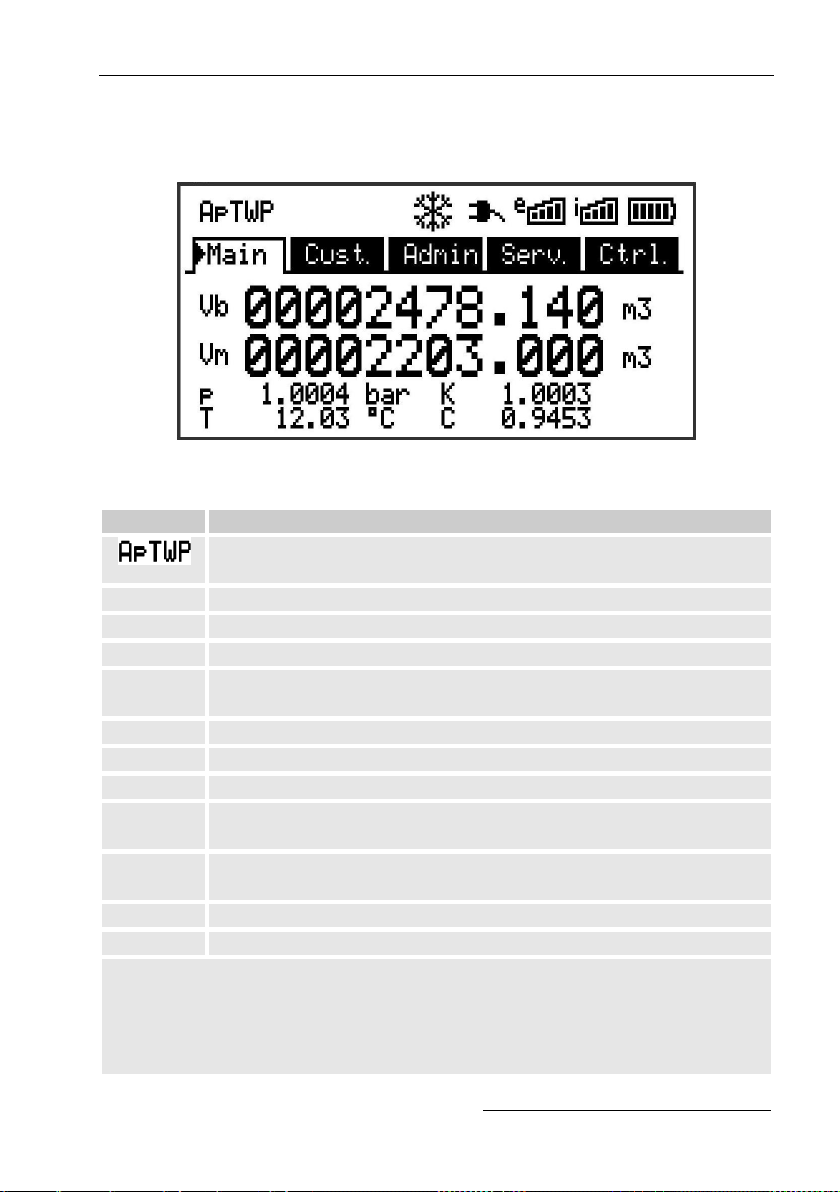
Operation 67
6.3.4 Meaning of status symbols
The status symbols displayed in the first line have the following meaning:
Fig. 26: Status symbols in the display
Symbol
Meaning
In the upper left-hand side of the screen, individual letters are
displayed as symbols for the following signals:
ok.
No special message.
A
Alarm – Collective message for "any alarm"
p
Pressure alarm – The gas pressure cannot be measured
T
Temperature alarm – The gas temperature cannot be
measured
W
Warning – Collective message for "any warning"
B
Battery warning – The battery is almost empty
L4
Certification data log - The certification data log is full
P
Calibration lock ("programming mode") - The calibration lock
is open
M
Measurement error - The connected gas meter encoder is not
giving accurate meter readings
o
Online – A data transfer is underway
a
Administrator lock is open
If one of these letters (above) flashes, the indicated status remains active.
If one of the letters is displayed constantly, the indicated status is no
longer active but must be acknowledged.
For further details on the meaning and potentially necessary procedures,
see chapter 8.1.4 "Behaviour in the event of faults"
4
If a configuration log is in a device.
Page 68

68 Operation
Symbol
Meaning
Frozen display
The displayed values have "frozen" (are not up-to-date). The
current values will be displayed after pressing any button. The
display freezing can be caused by pressing the function key
.
External power supply
If this symbol appears, the EK280 is being supplied power
from an external unit connected to the terminals.
Signal strength of the radio network for the external modem
(connected to the terminals). This symbol will only be shown if
an external modem has been connected and is active.
Signal strength of the radio network for the internal (in-built)
modem.
This symbol will only be shown if the in-built modem is active.
Charge status of the battery
6.3.5 Error messages when entering values
If a value has been entered incorrectly via the keyboard, input error
messages will be displayed.
This is shown as follows: --x-- with x = error code according to the
following table
Code
Description
1
The archive is empty. No values have been entered.
2
The archive value cannot be read.
The archive may already have been opened by the interface for
readings.
4
This parameter cannot be changed (constant).
5
You are not authorized to change this value.
To change this value, a corresponding lock must be opened.
6
Invalid value
The value entered is outside the permissible limits.
7
Incorrect code
The code entered (numerical code) is incorrect; the lock will not
be opened.
11
Input not possible due to special settings or configuration, e.g.
- The input of „Vm“ and „VmD“ is not possible in encoder
mode.
- The calorific value can only be changed in the gas analysis
list; not in the energy list.
Page 69

Operation 69
Code
Description
12
The input of this source (address) is not permitted.
13
Entry based on specific setting or configuration not possible,
e.g.:
- This function „Clr.X“ can only be performed once the time has
been set to its start value with the key combination + .
- The function „Store“ can only be performed once the change
information for comparison of „Vm“ (see chapter 5.3.1.7) or
„Vb“ (see chapter 5.3.1.9) has been deleted.
14
Gas analysis parameters do not correspond.
20
Value has not been defined for the user-specific display.
The displayed value can be defined by the user by entering the
address. As this address, has not yet been entered, no value
will be displayed.
21
The value can only be changed when the calibration lock is
open as the PTB log is full.
6.3.6 Access rights
The following parties can access the EK280.
Access
Meaning
C
Calibration officer
CDL5
Certification data log
A
Administrator
Cu
Customer
-
No access
Each access party has one lock and a corresponding key.
The access rights apply for entries made via the keyboard, and for access
via the optical, electrical (hard-wired) or integrated modem interface. If the
lock is closed, all attempts to enter values will result in a corresponding
error message being displayed (see chapter 6.3.5 “Error messages when
entering values").
For data protection reasons, reading values from the interfaces is only
possible if one of the locks is open.
5
If a configuration log is in a device.
Page 70

70 Operation
6.3.6.1 Calibration lock
The calibration lock is used to protect parameters subject to calibration
regulations. This includes all values which influence volume readings or the
volume conversion.
The calibration lock is designed as a button which is positioned inside the
EK280 housing underneath the circuit board cover. It can be protected with
an adhesive label (see chapter 5.3.1.1).
The calibration lock is opened by pressing the button ("P" symbol flashes in
the display) and is closed again by pressing the same button ("P" symbol
fades). It can also be closed by deleting the value "St.PL" (see chapter
6.4.6) via the keyboard or interface. Using the configuration software
"enSuite", a time can also be set (in minutes) after which the calibration
lock will automatically close.
The level of protection can be changed for all parameters upon request,
particularly for applications which are not subject to German calibration
guidelines or the MID.
For example, parameters which are protected by the calibration lock as
standard, can also be protected with a administrator's lock or a certification
data log.
6.3.6.2 Certification data log
The certification data log is activated as standard but can also be disabled.
The corresponding parameters will then be protected by the calibration
lock.
Using the "certification data log" as per PTBA 50.7, several parameters
subject to calibration regulations can also be adjusted when the calibration
lock is closed. This is subject to the following conditions:
– The administrator's lock (see below) must be open.
– There are at least three free entries in the certification data log.
The following parameters are set as default:
– "cp.I1" cp value for input 1
– "MPer" measurement period
– "Md.K" K-factor mode
– "Clr.A" delete measurement archive
– "Md.I1" mode for input 1
– "qMax" maximum flow (plausibility check in encoder mode)
For every change of a parameter listed under "CDL" when the calibration
lock is closed, one row of data will be entered for the value before and after
the change.
Page 71

Operation 71
If the certification data log is full, it can be deleted using the command
“ClCDL” if the calibration lock is open (see chapter 5.3.1.16).
If the calibration lock is opened when the certification data
log is full, it can only be closed again after the certification
data log has been deleted.
6.3.6.3 Administrator and customer locks
Administrator and customer locks are used to protect data which is not
subject to calibration regulations, but which should also not be modified
without authorization.
These locks can be opened by entering a code (i.e. the "key") under
“Cod.A” or “Cod.C” and are closed by entering "0" for “St.AL” or “St.CL”.
These values can be found under the following path:
Admin Device settings Access
or Serv. Device settings Access
A time (in minutes) can also be set here for each lock, after which it will
automatically close.
Page 72

72 Operation
6.4 Data register content
6.4.1 Access rights
The "Access" column in the tables in the following chapter describes which
lock must be opened in order to change a parameter. All parameter
changes are saved in a log.
Access
Meaning
C
Calibration officer
CDL6
Certification data log
A
Administrator
Cu
Customer
-
No access
6.4.2 "Main" register (main display)
An overview of the most important measurements is presented in the
"Main" register. The contents may vary depending on the parameterization
( chapter 6.4.6.5).
It is not possible to move the cursor to a value in this register7. By pressing
the "ENTER" button, the displayed values are updated.
Display
Meaning
Unit
Access
Address
Vb
Volume at base conditions
m3 C 2:300
Vm
Volume at measurement
conditions
m3 C 4:300
P
Pressure
bar - 7:310_1
K
Compressibility ratio factor
- - 8:310
T
Temperature
°C - 6:310_1
C
Conversion factor
- - 5:310
6.4.2.1 Vb – Volume at base conditions
The volume measured by the connected gas meter will be converted into a
quantity at base conditions and totalled in this counter.
If there is a fault (see chapter 8 "Faults"), the Vb counter will be stopped
and the volume will be totalled in a special disturbance quantity counter.
6
If a configuration log is in a device.
7
The exception is if the „Main“ tab was set to „List“ (see chapter 6.4.6.5).
Page 73

Operation 73
6.4.2.2 Vm – Volume at measurement conditions
The volume measured by the connected gas meter will be totalled in this
counter.
If there is a fault (see chapter 8 "Faults"), the Vm counter will be stopped
and the volume will be totalled in a special disturbance quantity counter. To
control the measurements, the Vm can be kept at the same level as the
gas meter when putting the device into operation ( chapter 5.3.1
"Configuration of measurement parameters").
6.4.2.3 p – Gas pressure
The measured gas pressure is used to calculate the volume at base
conditions. The pressure is displayed as absolute pressure.
If the pressure cannot be measured due to a fault, an adjustable
replacement value is displayed and is used to calculate the disturbance
quantity. The replacement value is determined when putting the device into
operation ( chapter 5.3.1 "Configuration of measurement parameters").
6.4.2.4 T – Gas temperature
The measured gas temperature is used to calculate the volume at base
conditions.
If the temperature cannot be measured due to a fault, an adjustable
replacement value is displayed and is used to calculate the disturbance
quantity. The replacement value is determined when putting the device into
operation ( chapter 5.3.1 "Configuration of measurement parameters").
6.4.2.5 K – Compressibility ratio factor
The calculated compressibility ratio factor is used to calculate the volume at
base conditions.
The EK280 supports several equations to calculate the compressibility ratio
factor. The corresponding equation is determined by the applicable
guidelines and standards for the area of application of the device. This can
be adjusted at the ordering or commissioning phase ( chapter 5.3.1
"Configuration of measurement parameters").
6.4.2.6 C – Conversion factor
The currently valid factor for converting the volume at measurement
conditions to base conditions.
Page 74

74 Operation
6.4.3 "Cust." register (Customer)
This register is used to display and check special device settings and
conditions. This application is provided for gas customers.
This register can be freely programmed by the user via the enSuite
configuration software.
The following parameters are programmed in-house:
Display
Meaning
Unit
Access
Address
Time
Date and time
- - 1:400
Vb
Volume at base conditions
m3 C 2:300
Vm
Volume at measurement
conditions
m3 C 4:300
p
Pressure
bar - 7:310_1
T
Temperature
°C - 6:310_1
K
Compressibility ratio factor
- - 8:310
C
Conversion factor
- - 5:310
SReg
Status register (total)
- - 1:101
VbMP
Maximum measurement period
counter Vb in the current month
- - 3:161
VbDy
Maximum daily counter Vb in
the current month
- - 4:161
Qb
Flow at base conditions
m3/h
-
2:310
Qm
Actual flow rate
m3/h
-
4:310
6.4.3.1 Time - Date and time
The displayed time is updated every 30 seconds in battery mode and every
2 seconds in power supply operation.
6.4.3.2 Values from the "Main" register
Vb – Volume at base conditions, see chapter 6.4.2.1
Vm – Volume at measurement conditions, see chapter 6.4.2.2
p – Gas pressure, see chapter 6.4.2.3
T – Gas temperature, see chapter 6.4.2.4
K – Compressibility ratio factor, see chapter 6.4.2.5
C – Conversion factor, see chapter 6.4.2.6
6.4.3.3 SReg – Status register (total)
Page 75

Operation 75
In the status register all messages since the last manual clearing are
collected. Here, you can also see what has happened, for example, since
the last station inspection. The messages can be cleared at the device
(Serv. -> Status -> Clr).
Only alarms and warnings ( chapter 8.2) are displayed in status registers.
6.4.3.4 VbMP – Maximum measurement period counter Vb in the
current month
The maximum time stamp is displayed in the following line after moving the
cursor to the value "VbMP".
The maximum values from the past 15 months can be requested in the
monthly archive 1 (see chapter 6.4.4 "Admin" register (Administrator).
6.4.3.5 VbDy – Maximum measurement period counter Vb at the
current day
The time stamp for the maximum value is displayed in the following line
when moving the cursor to th
e value "VbDy".
The maximum values from the past 15 months can be requested in the
monthly archive 1 (see chapter 6.4.4 "Admin" register (Administrator).
6.4.3.6 Qb – Flow at base conditions
Current flow at base conditions (standard flow rate)
Qb = Qm C with Qm = actual flow rate
C = Conversion factor
The maximum inaccuracy of the displayed value roughly corresponds to
the maximum inaccuracy of the Qm.
For the alarm, the Qb is calculated with the replacement values of the
disturbed measurements.
6.4.3.7 Qm – Actual flow rate
Current actual flow rate (measurement flow rate)
The measurement inaccuracy of the displayed actual flow rate is
dependent on whether a pulse transducer or encoder is connected:
If a pulse transducer is connected:
For a maximum pulse interval of 15 minutes (at least four pulses per hour)
and
cp.I1 1, the measurement inaccuracy of Qm is maximum 1%. For a pulse
Page 76

76 Operation
interval of more than 15 minutes, Qm = "0" will be displayed. After the gas
flow rate has changed, the precise value can only be displayed if at least
two pulses have been transmitted to the gas meter.
If an encoder is connected:
If the meter reading changes every two seconds or less, the measurement
inaccuracy of Qm will be max. 1%.
If the meter reading changes every 200 seconds or less, the measurement
inaccuracy will be max. 10%. This can be reduced by decreasing the
measurement cycle (Serv. -> Device settings -> Measurement -> MCyc) by
up to 2% for MCyc = 4 seconds.
If the meter reading of the encoder does not change after 200 seconds, Qm
= "0" will be displayed.
6.4.4 "Admin" register (Administrator)
This register is used to display and check special device settings and
conditions. This application is provided for metering point operator.
Display
Meaning
User values8
Sub-menu for user-specific parameters
Volume
Sub-menu for volume and the corresponding parameters
Volume
conversion
Sub-menu for volume conversion and the corresponding
parameters
Measured
values
Sub-menu for measured values and the corresponding
parameters
Archives
Sub-menu for existing archives in the device
Status
Sub-menu for current status, status register and logs
Date and time
Sub-menu for date, time and the corresponding
parameters
Batteries
Sub-menu for the device battery and the corresponding
parameters
Inputs
Sub-menu for inputs and the corresponding parameters
Outputs
Sub-menu for all outputs and the corresponding
parameters
Interfaces
Sub-menu for device interfaces
Device
settings
Sub-menu for all device settings
Identification
Sub-menu for the identification of the gas system
8
In the "User Values" sub-menu, the user can set up to 10 freely programmable parameters
and up to 12 freely programmable parameters in a further sub-menu within this list.
Page 77

Operation 77
6.4.5 "Serv." register (service)
This register is used to display, check and configure special device settings
and conditions. This application is only intended for service technicians
(specialists) or a calibration officer for putting the device into operation or
maintenance.
Display
Meaning
Volume
Sub-menu for volume and the corresponding
parameters
Volume
conversion
Sub-menu for volume conversion and the corresponding
parameters
Measured values
Sub-menu for analogue measurements and the
corresponding parameters
Archives
Sub-menu for existing archives in the device
Status
Sub-menu for current status, status register and logs
Date and time
Sub-menu for date, time and the corresponding
parameters
Batteries
Sub-menu for device battery and the corresponding
parameters
Inputs
Sub-menu for inputs and the corresponding parameters
Outputs
Sub-menu for all outputs and the corresponding
parameters
Interfaces
Sub-menu for device interfaces
Device settings
Sub-menu for all device settings
Identification
Sub-menu for the identification of the gas system
Edit and delete
Sub-menu to activate a range of delete functions
Examination
Sub-menu with freeze function and archive with frozen
data
Data book
Sub-menu with information from the device data book
Page 78

78 Operation
6.4.6 "Ctrl." register (Control)
This register is used to monitor special device settings. This application is
only intended for service technicians (specialists) or a calibration officer for
putting the device into operation or maintenance.
Display
Value
Unit
Access
Address
St.AL9
Administrator lock: State / close
- - 3:170
Cod.A9
Administrator key enter / change
- - 3:171
St.PL
Calibration lock: State / close
- - 1:170
Menu
Selection of the display menu
- C 1:1A1
Main
Content of the "Main" register
- A 2:1A1
6.4.6.1 St.AL – Administrator lock: State / close
The administrator lock must be opened in order to modify certain
measurement parameters. The administrator lock should be closed when in
normal operating mode.
Display
Meaning
locked
The administrator lock is closed.
open
The administrator lock is open.
6.4.6.2 Cod.A – Administrator key enter / change
By entering the right key (hexadecimal notation) the administrator lock can
be opened. After the administrator lock is open the key can be changed.
The individual characters of the key can take on values from 0 to 9 and
from A to F.
6.4.6.3 St.PL – Calibration lock: State/close
The calibration lock must be opened in order to modify certain
measurement parameters. The calibration lock should be closed when in
normal operating mode.
Display
Meaning
locked
The calibration lock is closed.
open
The calibration lock is open.
In this case, the "P" will also flash in the upper left-hand side
of the display (see chapter 6.3.4 "Meaning of status symbols")
6.4.6.4 Menu - Selection of the display menu
In an as-delivered condition, the display of the EK280 has the following five
9
When using the device with high communication security („High Level Security“ see
application manual), the parameter will not be displayed.
Page 79

Operation 79
registers: "Main", "Cust.”, "Admin", "Serv." and "Ctrl.". Registers can be
displayed and hidden for certain purposes using the "Menu" value.
6.4.6.5 Main – Content of the "Main" register
The content of the "Main" display register can be adjusted here.
The default setting is "volume+meas.”. This corresponds to the content
displayed in chapter 6.3.1.
Display
Meaning
volume+meas
.
- The following are displayed: Volume at base conditions,
volume at measurement conditions, pressure, temperature, compressibility ratio factor and conversion factor
- Format: 8 pre-decimal and 3 post-decimal places for
counters
- With short descriptions for each value
volume short
- The following are displayed: Volume at base conditions
and volume at measurement conditions
- Format: 8 pre-decimal and 3 post-decimal positions
respectively
- With short descriptions
volume long
- The following are displayed: Volume at base conditions
and volume at measurement conditions
- Format: 9 pre-decimal and 4 post-decimal places
- Without short descriptions
volume,p,T,Q
- The following are displayed: Volume at base conditions,
volume at measurement conditions, pressure,
temperature, flow at base conditions and actual flow rate
- Format: 8 pre-decimal and 3 post-decimal places for
counters
- With short descriptions for each value
List
- The following are displayed: Volume at base conditions,
volume at measurement conditions, total meter reading
the original meter reading of the gas meter at Input DE1,
pressure, temperature, Conversion factor,
compressibility ratio factor, actual flow rate, flow at base
conditions, date and time
Vb,Vo,meas.
- The following are displayed: Volume at base conditions,
meter reading of the gas meter (Encoder), pressure,
temperature, compressibility ratio factor and conversion
factor
- Format: 8 pre-decimal and 3 post-decimal places for
counters
- With short descriptions for each value
Page 80

80 Maintenance
7 Maintenance
7.1 Safety
DANGER!
Danger to life from electrical current!
Touching live parts poses an imminent danger to life.
Damage to the insulation or individual components may be
life-threatening.
Therefore:
– Safely protect electrical connections and live
components against possible human contact.
– In the event of insulation damage, switch off the power
supply immediately and arrange for repairs to be carried
out.
– Works on the electrical components of the device, i.e.
the connection of the external power supply unit, should
only be carried out by qualified electricians.
– When performing all works to the electrical system,
switch off the power and ensure that the voltage has
been cut.
– Before performing maintenance works, switch off the
power supply and protect against an accidental restart.
– Do not attempt to bypass or deactivate fuses. When
exchanging fuses, ensure that you adhere to the correct
ampere rating.
– Keep live parts away from moisture. This could lead to a
short-circuit.
Page 81

Maintenance 81
WARNING!
Misuse of batteries may present a risk of injury.
Special care must be taken when handling batteries.
Therefore:
– Do not throw the batteries into the fire or expose these
to high temperatures. There is a risk of explosion.
– Do not charge batteries. There is a risk of explosion.
– Liquids that are produced as a result of misuse may lead
to skin irritation. Avoid all contact with liquids. In the
event of contact, rinse with large quantities of water. If
the liquid enters the eyes, immediately rinse with water
for 10 minutes and seek medical attention.
CAUTION!
Environmentally hazardous substances!
If environmentally hazardous substances are handled
incorrectly this may cause significant damage to the
environment, particularly if they are improperly disposed of.
Therefore:
– The instructions below should be observed at all times.
– Appropriate measures should be taken immediately if
environmentally hazardous substances are accidentally
released into the environment. In cases of doubt, please
inform the responsible local authority about the damages.
Page 82

82 Maintenance
7.1.1 Personnel
Maintenance works must be carried out correctly.
– The maintenance works described in this document should solely be
carried out by specialized electricians (see "Operation" chapter).
WARNING!
Risk of injury if maintenance works are carried out
incorrectly.
Incorrect maintenance may lead to serious personal injury or
material damage.
Therefore:
– Ensure that there is sufficient assembly space before
commencing works.
– Ensure that the installation location is clean and tidy.
Components that are loosely stacked or lying around can
cause accidents.
– If parts have been removed, ensure that they have been
installed correctly, re-mount all fastenings, and adhere to
tightening torque values for screws.
7.1.2 Personal protective equipment
– During maintenance works on the device, the necessary personal
protective equipment for the work must be worn inside the respective
plant.
– The notices relating to personal protective equipment mounted in the
working area must be followed at all times.
7.1.3 Environmental protection
Please observe the following notice regarding environmental protection
when performing maintenance works:
The batteries used contain toxic heavy metals. These must
be treated as special hazardous waste and must be disposed
of in municipal waste collection points or by a waste
specialist.
Page 83

Maintenance 83
7.2 Testing and changing device batteries
7.2.1 Changing and connecting device batteries
DANGER!
Using the incorrect batteries may present a risk of
explosion!
Connect only the prescribed Elster battery-types to the device
(see chapter 9.1.4.
WARNING!
Misuse of batteries may present a risk of injury.
Special care must be taken when handling batteries.
Therefore:
– Do not throw the batteries into the fire or expose them to
high temperatures. There is a risk of explosion.
– Do not charge the batteries. There is a risk of explosion.
– Liquids that are produced as a result of misuse may lead to
skin irritation. Avoid all contact with liquids. In the event of
contact with the skin, rinse with plenty of water. If the liquid
enters the eyes, immediately rinse with water for 10
minutes and seek medical attention.
CAUTION!
Reduced battery power!
The simultaneous use of old and new batteries considerably
reduces battery power.
Therefore:
– You should always replace all batteries together.
The batteries can be exchanged without a calibration officer as the housing
does not need to be sealed.
In an as-delivered condition, two batteries are connected to
the base board of the EK280. To double the service life of the
batteries, two additional batteries can be connected.
You should always connect at least two batteries (to X10 and
X13 or X11 and X14) to the EK280. This way, the EK280 will
continue to work whilst the batteries are being changed.
Page 84

84 Maintenance
Fig. 27
1. If the external power supply is
connected, this should be
removed.
2. Loosen the four screws Fig. 27: 1
which are keeping the housing
closed.
3. Open the cover of the EK280.
4. Loosen the screws on the battery
cover Fig. 28: 1 or 2 and
remove the battery cover.
Fig. 28
Fig. 29
5. Mark the old batteries, e.g. using
a felt-tipped pen or stickers.
6. Select the two free connections
on the board to connect the new
batteries (X10 and X13 or X11
and X14, Fig. 29).
7. Place the new batteries inside
(Fig. 28: 1 or 2 ).
8. Position the new batteries and
secure them using the battery
cover.
9. Remove the old batteries from the
housing and dispose of these
correctly.
10. Close the housing using the
screws provided (Fig. 27: 1 ).
11. Re-enter the start capacity of the batteries, as described in chapter
7.2.2.
12. Check the calculated service life as described in chapter 7.2.3. At
standard measurement conditions (see chapter 3.2.1), the service
life should display at least 60 months. If not, compare the settings
with those for standard measurement conditions and repeat step 11
if necessary.
Please ensure that the new batteries are connected
correctly and are in a fixed position inside the EK280.
1
1
2
Page 85

Maintenance 85
CAUTION!
Material damage may arise through improper closing of
the device!
Improper closing of the device may lead to material damage
as a result of cable connections being squashed.
Therefore:
– When closing, ensure that the cable ducts are positioned
correctly.
7.2.2 Entering the battery capacity
The battery capacity must be re-entered after changing a
battery.
When using the device with high communication security
(„High Level Security“ see application manual), the battery
capacity can only be entered with the enSuite software!
– For opening the administrator lock move the cursor to the "Admin"
register and to the "Cod.A" value (enter administrator key) via the
following path:
Admin. Device settings Access Cod.A
After delivery of the device, the administrator key for input
via keypad is "00000000".
– Press the ENTER button. The value will start to flash.
– Move the cursor using the arrow keys or to the digits and
change these using the arrow keys or .
– After you have changed all digits, press the ENTER button to confirm
the inputs. The input value can be deleted by pressing the ESC
button.
– For entering the battery capacity move the cursor to the "Serv."
register and to the "Bat.C" value (battery capacity) via the following
path:
Serv. Batteries Bat.C
– Press the ENTER button. The value will start to flash.
– Move the cursor using the arrow keys or to the digits and
change these using the arrow keys or .
Page 86

86 Maintenance
When using two size D batteries, the value 13.0 Ah should
be entered for "Bat.C". When using four batteries, the value
26.0 Ah must be entered.
– After you have changed all digits, press the ENTER button to confirm
the inputs. The input value can be deleted by pressing the ESC
button.
– For closing the administrator lock move the cursor to the "Admin"
register and to the "St.AL" value (status administrator lock) via the
following path:
Admin. Device settings Access St.AL
– Press the ENTER button. ”open“ will start to flash.
– Move the cursor using the arrow keys or to change the value to
“locked”.
– After you have changed the value, press the ENTER button to
confirm the inputs. The input value can be deleted by pressing the
ESC button.
7.2.3 Display remaining battery power
The remaining battery power is calculated separately from
the consumed power (which is measured) and from the
anticipated future consumption (giving the theoretical
remaining battery power). Therefore, for applications which
are very power-consuming, the remaining battery power
may drop quicker than is shown on the battery power
display.
The remaining battery power will automatically be
recalculated after entering a new battery capacity “Bat.C“
(see above). The value cannot be edited.
– Move the cursor to the "Serv." register and to the "Bat.R" value
(remaining battery power) via the following path:
Serv. Batteries Bat.R
After entering the new battery capacity, a value of at least
60 months will be displayed in standard measurement
conditions (see chapter 3.2.1) for "Bat.R".
Page 87

Faults 87
8 Faults
Possible causes and solutions for device faults will be described in the
following chapter.
For faults, which cannot be resolved by the instructions
below, please contact our customer service team (see
chapter General) or our Electronic Hotline:
Tel. +49 (0) 6134 / 605-123
http://www.elster-instromet.com/de/support
E-Mail: ElsterSupport@honeywell.com
8.1 Safety
DANGER!
Danger to life from electrical current!
Touching live parts poses an imminent danger to life.
Damage to the insulation or individual components may be
life-threatening.
Therefore:
– In the event of insulation damage, switch off the power
supply immediately and arrange for repairs to be carried
out.
– Works on the electrical components of the device, i.e. the
connection of the external power supply unit, should only
be carried out by qualified electricians.
– When performing all works to the electrical system, switch
off the power and ensure that the voltage has been cut.
– Before performing maintenance works, switch off the
power supply and protect against an accidental restart.
– Keep live parts away from moisture. This could lead to a
short-circuit.
Page 88

88 Faults
8.1.1 Personnel
– The works described below for the elimination of a fault can, unless
specified otherwise, be performed by the operator.
– Some works may only be carried out by specially trained
professionals or exclusively by manufacturers themselves; special
reference will be made to this in the descriptions of individual faults.
– Works on the electrical appliance may only be carried out by qualified
electricians.
8.1.2 Personal protective equipment
– When eliminating faults on the device, the necessary personal
protective equipment for the work must be worn inside the respective
plant.
– The notices relating to personal protective equipment mounted in the
working area must be followed at all times.
8.1.3 Improper elimination of faults
WARNING!
Risk of injury through improper elimination of faults!
An improper elimination of faults on the device may lead to
serious personal injury or material damage.
Therefore:
– Ensure that there is sufficient assembly space before
commencing works.
– Ensure that the installation location is clean and tidy.
Components that are loosely stacked or lying around can
cause accidents.
– If parts have been removed, ensure that they have been
installed correctly, re-mount all fastenings, and adhere to
tightening torque values for screws.
The following information on possible faults provide
indications as to who is authorized to eliminate the fault.
Page 89

Faults 89
8.1.4 Behaviour in the event of faults
The following generally applies:
1. If works in the danger zone are necessary, the entire plant must be
switched off and protected against an accidental restart.
2. The cause of the fault must be determined.
3. The person responsible for the area in which the fault occurred should
be informed immediately.
4. Depending on the type of fault, the manufacturer may have to be
contacted and will then have the fault removed by an authorized
specialist or will remove the fault themselves.
8.2 Fault and other status messages
Faults (synonymously used here for "alarms") during the operation of the
EK280, can be identified by means of status symbols in the first line of the
display (see chapter 6.3.4).
You can obtain further information and messages under the current status
"Stat" and in the status register "SReg". These can be found:
In the “Cust.” register (only "SReg")
Under the path: Admin Status
Effects and recommended action in the event of fault and status messages:
Message
Meaning, action
a) Faults, alarms:
Restart
If this message appears whilst in operation, the device
is faulty.
Please contact the Elster support (see chapter 1.3
"Customer service").
C-fact. err.
The conversion factor could not be calculated as the
measured gas temperature was outside -100°C to
+100°C or no usable compressibility ratio factor was
available.
Data error
An error was detected during the cyclic check of the
data subject to calibration regulations.
Please contact the Elster support (see chapter 1.3
"Customer service").
T Alarm Lim.
The measured gas temperature is outside the
permissible limits.
The limit values can be changed when putting the
device into operation in the presence of a calibration
officer (see chapter 5.3.1.11, page 55)
Page 90

90 Faults
Message
Meaning, action
p Alarm Lim.
The measured gas pressure is outside the permissible
limits.
The limit values can be changed when putting the
device into operation in the presence of a calibration
officer (see chapter 5.3.1.11, page 55)
K-val. error
The compressibility ratio factor could not be calculated
as no valid real gas factor could be determined.
z-fact. err.
The real gas factor could not be calculated.
At least one of the gas analysis values Ho.n, CO2, H2,
rhon, is outside the permissible range.
Vm-Alarm
No volume was recorded at the used input for
conversion. (The automatic switchover of the pulse
transducer to a second pulse transducer is not
configured acc. chapter 5.2.1.4.).
Vm-Inp.Alarm
No volume at measurement conditions was recorded at
the connected encoder on input 1 for 20 seconds (with
ext. power supply) or for two measurement cycle + 1
second (battery powered).
T Inp. error
The gas temperature cannot be measured due to a
fault.
Please contact the Elster support (see chapter 1.3
"Customer service").
p Inp. error
The gas pressure cannot be measured due to a fault.
Please contact the Elster support (see chapter 1.3
"Customer service").
b) Warnings:
Data restore
The batteries of the EK280 are intermittently dropping
out. As a result of this, the time has not changed and no
measurement and volume conversion have happened.
However, all data is available.
This message appears when old batteries are removed
before connecting the new ones (see chapter 7.2).
Proceed with the help of the configuration program
"enSuite":
– Set the time of the EK280
– Delete the status register
Page 91

Faults 91
Message
Meaning, action
Outp.1 Error
Outp.2 Error
Outp.3 Error
Outp.4 Error
There should be more pulses being emitted from the
specified output than are permitted under its configured
settings.
In order to eliminate the cause of the problem, you can
use the configuration program "enSuite" to either:
– reduce the cp value of the output
– or increase the output frequency.
In both cases, the change must be aligned with the
connected device.
I1-Warning
The encoder could not be read at the end of the
measurement period. The flow recording at this point is
invalid.
I2 Pulse cmp
In the pulse comparison, e.g. between input 1 and input
2, the deviation was too high.
W Warn Lim.
The displayed value is outside the set warning limit
values.
The warning limits can be adjusted using the
configuration program "enSuite".
Vb Warn Lim.
The monitored volume at base conditions consumption
value (standard: hourly consumption) is outside the set
warning limit values.
The monitored values and the warning limits can be
adjusted using the configuration program "enSuite".
Vc Warning
The parameters for the corrected volume at
measurement conditions are not sorted in ascending
order or one of the values is outside the permissible
limits.
Qm Warn Lim.
The actual flow rate (gas flow rate) is outside the set
warning limit values. The warning limits can be adjusted
using the configuration program "enSuite".
T Warn Lim.
The measured gas temp. is outside the warning limit
values.
The warning limits can be adjusted using the
configuration program "enSuite".
p Warn Lim.
The measured gas pressure is outside the warning limit
values.
The warning limits can be adjusted using the
configuration program "enSuite".
Page 92

92 Faults
Message
Meaning, action
z Warning
The sum of gas analysis values for AGA-8 DC92 is
more or less than 100%. An accurate calculation of the
real gas factor and the compressibility ratio factor can
therefore not be carried out.
Vm warning
If a HF-NF switch is configured, then this message is
enabled in the event of a fault at the HF input, e.g. loss
of external power supply.
Update error
Before the software update, an error was detected in
the cached software image.
Softw. error
This message is used for factory diagnosis.
Please contact the Elster support (see chapter 1.3
"Customer service").
Sett. error
The programming of the device has generated an unusable
combination of settings.
Please contact the Elster support (see chapter 1.3 "Customer
service").
I2 Warn.sig.
I3 Warn.sig.
I4 Warn.sig.
I5 Warn.sig.
I6 Warn.sig.
If an input has been configured as a warning input, this
message will be displayed if an active signal appears at
the corresponding terminal (e.g. terminal DE2).
The input configuration can be adjusted using the
configuration program "enSuite".
T2 Warn Lim.
The measured gas temperature of the second sensor is
outside the set warning limit values.
The warning limits can be adjusted using the
configuration program "enSuite".
p2 Warn Lim.
The measured gas pressure of the second sensor is
outside the set warning limit values.
The warning limits can be adjusted using the
configuration program "enSuite".
Batt. low
The remaining battery power is less than six months.
The batteries need to be changed soon.
c) Signals:
TA Warn Lim.
The measured ambient temperature is outside the set
warning limit values.
The warning limits can be adjusted using the
configuration program "enSuite".
Repair mode
The device is in revision mode.
Clock n. set
The internal clock of the volume corrector has not been
adjusted at the factory.
Page 93

Faults 93
Message
Meaning, action
Encoder err.
No volume at measurement conditions was recorded at
the connected encoder on input 1 for 20 seconds (with
ext. power supply) or for one measurement cycle + 1
second (battery powered).
CDL full
The certification data log is full. Changing the
parameters marked with "CDL" without a calibration
lock is only possible if the content of the certification
data log has been deleted.
U.Logb. full
The software update log is full. An update is only
possible if the content of the software update log has
been deleted.
online
Data is currently being transmitted via an interface
(modem, optical interface, terminal interface or Ethernet
adapter). If this message is displayed, the "o" will flash
in the "Status" field of the display
(see chapter 6.3.4, page 67).
I2-Rep.sig
I3-Rep.sig
I4-Rep.sig
I5-Rep.sig
I6-Rep.sig
If an input has been configured as a signal input, this
message will be displayed if an active signal has
appeared at the corresponding terminal (e.g. terminal
DE2).
The input configuration can be adjusted using the
configuration program "enSuite".
Cal.lock
The calibration lock is open.
In normal operating conditions, the calibration lock
should be closed to prevent unauthorized changes.
To close the calibration lock, please go to
Ctrl. St.PL and enter the value "0".
Admin.lock
Cust.lock o.
The administrator / customer lock is open.
Bat. operat.
The EK280 is in battery mode.
This signal is primarily used to inform a remote data
transmission system that the batteries run down more
quickly during long periods of data transmission.
Dayl.Sav.Tim
The time displayed in volume corrector is daylight
saving time.
The switchover mode can be changed using the
configuration program "enSuite".
Page 94

94 Faults
Message
Meaning, action
Call Win.1
Call Win.2
Call Win.3
Call Win.4
Call Win.5
Call Win.6
The specified call pickup time is active, i.e. the volume
corrector will accept data transmission calls.
Page 95

Appendix 95
Images of the spare parts and accessories described below
can be found in the manufacturer's catalogue which is
available to order under www.elster-instromet.com.
Spare parts and accessories
Order no.
Set mounting bracket EK220/280 for MI-2
73 021 952
Set mounting bracket EK220/280 for Rabo
73 021 953
Set mounting bracket EK280 for S1/Encoder
73 021 954
Set Bracket EK/DL for pipe mounting
73 021 955
Universal bracket with pipe clamps for pipe mounting
73 018 057
Mounting bracket for meter head S1D
73 021 050
When ordering the universal bracket with pipe clamps for
pipe mounting, please specify the pipe diameter.
Spare parts and accessories
Order no.
Shut-off valve with t-piece
03 152 266
Three-way check valve
73 008 403
Pressure pipe C2 6 x 700 mm
73 017 659
Pressure pipe C5 6 x 400 mm
73 017 656
Minimess test connections (adapters)
73 016 167
Spare parts and accessories
Order no.
Temp. sensor pocket EBL 50, with welded sockets M10 x 1
73 012 634
Temp. sensor pocket EBL 67, with welded sockets M10 x 1
73 014 456
Temp. sensor pocket EBL 160, with welded sockets G 3/4”
and sealing ring
73 012 100
Temp. sensor pocket EBL 250, with welded sockets G 3/4”
and sealing ring
73 015 695
9 Appendix
9.1 List of spare parts and accessories
9.1.1 Fastening elements
9.1.2 Pressure connections
9.1.3 Temperature sensor pockets
Page 96

96 Appendix
Sealing sleeve for the connection of an old temp. sensor
pocket EBL 45, 50 and 67
73 019 951
Sealing sleeve for the connection of an old temp. sensor
pocket EBL 160 and 250
73 019 950
9.1.4 Small parts and miscellaneous
Spare parts and accessories
Order no.
Sealing sleeve for pressure connection and temp. sensor
73 017 997
Connecting cable for two low frequency pulser transducers,
approx. 700 mm long
73 017 093
Device battery module 13 Ah
73 015 774
Device battery module 13 Ah10
730 23 225
16 Ah battery module for the modem of the EK280 without
integrated power supply unit
73 021 211
13 Ah battery module for connection to the integrated
power supply unit (modem battery mode in the event of
power failure)
73 017 964
Ext. GSM antenna, 3 m connecting cable, SMA connector
04 407 115
Ext. GSM antenna, 5 m connecting cable, SMA connector
04 407 116
Ext. GSM antenna, 10 m connecting cable, SMA connector
04 407 117
10 m antenna extension cable with SMA connector
73 020 149
2G/3G stub antenna, SMA, straight
04 407 113
Breather Drain Plug for outdoor application
73 020 775
9.1.5 Documentation
Spare parts and accessories
Order no.
German manual
73 021 805
English manual
73 021 209
10
After consultation for special applications.
Page 97

Appendix 97
9.2 EC Declaration of Conformity
Page 98

98 Appendix
9.3 ATEX Type Examination Certificate
9.3.1 Zone 0, 1
Page 99

Appendix 99
Page 100

100 Appendix
 Loading...