

Page 1

GB
F
NL
I
E
1000248560-002-05
03251009
D GB
I
➔ www.docuthek.com
Safety
Safety
Please read and keep in a safe place
Operating instructions for
operators and installers
Electronic index EI
© 2017 Elster GmbH · Edition 08.17
Translation from the German
Contents
Contents
Electronic index EI .....................
Contents ..............................
Safety.................................
Checking the usage .....................
Installation ............................
Operating the electronic index ............
Navigating within the menu ..............
Service mode ..........................5
Establishing an optical communications link 8
Setting the index parameters .............8
Replacing the communication module .....8
Changing the SIM card ..................9
Changing the battery ....................9
Electrical pulse output..................0
Check test............................0
Assistance in the event of malfunction ....4
Accessories ..........................4
Spare parts ...........................4
Technical data ........................4
Logistics .............................5
Contact ..............................6
carefully before installing or operating. Following the
Please read through these instructions
installation, pass the instructions on to the operator. This unit must be installed and commissioned
in accordance with the regulations and standards
in force. These instructions can also be found at
www.docuthek.com.
Explanation of symbols
• , , , ... = Action
▷ = Instruction
Liability
We will not be held liable for damage resulting from
non-observance of the instructions and non-compliant use.
Safety instructions
Information that is relevant for safety is indicated in
the instructions as follows:
DANGER
Indicates potentially fatal situations.
WARNING
Indicates possible danger to life and limb.
CAUTION
Indicates possible material damage.
All interventions may only be carried out by qualified
gas technicians. Electrical interventions may only be
carried out by qualified electricians.
Conversion, spare parts
All technical changes are prohibited. Only use OEM
spare parts.
Changes to edition .
The following chapters have been changed:
– Checking the usage
– Logistics
GB-1
Page 2
GB
F
NL
I
E
Checking the usage
*Current meter reading
Electronic index EI for diaphragm gas
meters BK-G...B
The electronic index EI3 indicates the volume at base
conditions. It can be used for reading out absolute
consumption values and for retrieving consumption
data for the various tariffs.
This function is only guaranteed when used within the
specified limits – see page14 (Technical data). Any
other use is considered as non-compliant.
Type code
Code Description
EI Electronic index based on EI3
.00
.05
▷
The index version is shown on the index plate,
ECM.05, GSM wireless technology
see page 2 (Type label/Index plate).
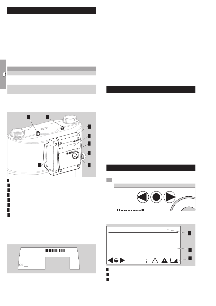
Part designations
87
5
Electronic index EI3
Display
User keys
4 Opto-adapter interface
5 Service cover
6 Pulse output
7 Pressure test point with sealing sleeve (optional)
8 Thermowell (optional)
Type label/Index plate
Please quote for all enquiries:
▷
Manufacturer’s serial number S/N (at the bottom left)
▷ Index version EI (next to the serial number)
BK-G..B
Q
max
t
m
Q
min
V
p
max
class 1,5
M ... 0102
S/N: ............
t
g
t
b
p
b
EI3. ...
V
b
12345678
Standard version
Communication module
1234 5678
BK-Gx
max
Q
min
Q
DE-07-MI002-PTB001
M07 0102
^
...
1 imp
=
Variant
1
2
3
6
4
ATEX
▷
The electronic index is suitable for use in po-
tentially explosive atmospheres. For the exact
use (zone), see ATEX sticker on the diaphragm
gas meter or see “Operating instructions for
diaphragm gas meters BK-G1.6 to BK-G25” →
http://docuthek.kromschroeder.com/doclib/
main.php?language=1&folderid=400041&by_
class=2&by_lang=-1
“Instruction Manual, Industrial Diaphragm Gas
Meters Type BK-G40 · BK-G65 · BK-G100
and Type BK-G40T · BK-G65T · BK-G100T” →
http://docuthek.kromschroeder.com/doclib/
main.php?language=1&folderid=400045&by_
class=2&by_lang=-1
Installation
Installing the gas meter
▷
For installing the gas meter in the pipework, see “Operating instructions for diaphragm gas meters BK-G1.6 to BK-G25” →
http://docuthek.kromschroeder.com/doclib/
main.php?language=1&folderid=400041&by_
class=2&by_lang=-1
“Instruction Manual, Industrial Diaphragm Gas
Meters Type BK-G40 · BK-G65 · BK-G100
and Type BK-G40T · BK-G65T · BK-G100T” →
http://docuthek.kromschroeder.com/doclib/
main.php?language=1&folderid=400045&by_
class=2&by_lang=-1
Operating the electronic index
▷ The display on the index is switched off.
• Briefly press any key.
▷ A beep sounds and the main screen appears.
Main screen
1
3
0000004
Tariff: F01
Menu area
Information area
Status line (symbols)
.00
*
m
2
3
GB-2
Page 3

GB
F
NL
I
E
User keys, selection key and symbols
=
*
*Date and time: (UTC + X)
▷
You can navigate through the menu using the
user keys , and the selection key .
Symbol Meaning
Navigate to the left or the right on each
,
level using the user keys.
Briefly pressing the selection key selects
a sub-menu.
Holding the selection key pressed down
switches the display back to the previous
menu.
Briefly pressing the selection key selects
a sub-menu.
Holding the selection key pressed down
switches the display back to the previous
menu.
Keys inactive
, ,
RF module/communication is active
RF module/communication is inactive
RF communication – pairing successful
Invalid data
Alarm
Low index battery. This symbol is only
displayed when battery power is low.
Temperature out of operational range
T
p
Pressure out of operational range
Multiple sensor data out of operational
range
▷ In each menu, the meaning of the symbols for
the keys is described in the information area.
▷ In the main screen under “General instructions”,
all the symbols are explained.
Navigating within the menu
▷ The menu is constructed hierarchically.
▷
The “Current meter reading” main screen appears
when switching on the index.
▷
If you are in a different menu, the display will
automatically change back to the main screen
when no user key has been pressed for 30s,
and switches off after a further 30s.
▷
You can navigate from the main screen to the
various menus, such as “Date and time (UTC)”
using the user keys
, .
Menu overview
Main menu
–
Current meter reading
General instructions
–
Date and time (UTC)
Past meter readings
–
Monthly
Daily
Hourly
–
Tariff information
–
Billing information
–
Metering point identification
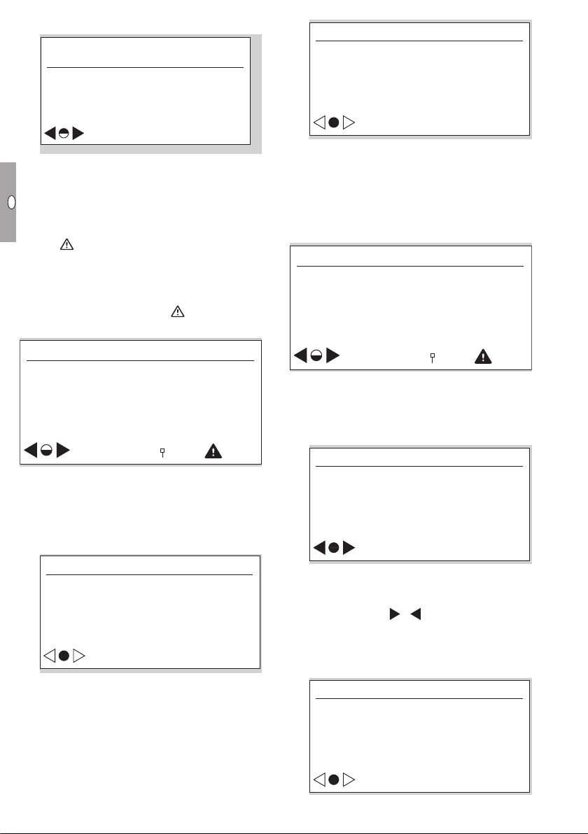
Current meter reading
▷
The absolute meter reading and optionally the
current tariff are indicated in the main screen.
▷ This appears when switching on the index.
▷
You can receive information about the symbols by
pressing the selection key and the user keys
, , or see page 3 (User keys, selection
key and symbols).
Date and time (UTC + X)
▷ UTC = coordinated universal time + X = offset
for conversion to local time.
▷ Information on the date and time display.
▷
The current date and time appears when the
selection key is pressed.
▷ Local time is supported.
▷ Daylight saving time can be supported.
▷
For further information, contact the meter operator.
20–04–2013
07:15:30
▷ The date is given in the format DD-MM-YYYY.
Past meter readings
▷
Consumption data dating as far back as
20 weeks can be called up.
▷ By pressing the selection key
data are displayed, which are given by month,
day or hour intervals:
M: monthly
D: daily
H: hourly
, consumption
GB-3
Page 4
GB
F
NL
I
E
▷ “hourly summary” example:
*H: 01-05-13 18:00->19:00
Billing information
Billing information (1/5)
0000000.00->0000004.00m
Vb
4.00m
Tariff: F02
▷
The timeframe is displayed with date and time
for the start and end of the period.
▷ The meter reading is displayed for the start and
end of the period in m3.
▷
The consumption for this period is indicated in m3.
▷ The tariff (e.g. F02) may be displayed.
▷ The symbol is displayed if, for example, the
tolerance between the internal time recording
and the actual time is too large. This can lead
to invalid consumption data. After the next time
synchronization, the consumption data are recorded again correctly and disappears.
Tariff information
Tari information
Tariff program &
Details
▷
This menu contains information on the current
tariff program.
▷
By briefly pressing the selection key, you can
access further information. Here, the active tariff
program is displayed, as are the date and time
of activation.
Tari information
ID :Green Spring Demo
From : 01-01-2000 06:00
▷
By briefly pressing the selection key, you can
visualize the consumption data.
Consumption results
3
3
F01: 0.00m
F02: 0.00m
F03: 0.00m
3
3
3
UES:0x0240000000000000
▷
In lines F01 to F03, the current absolute gas
consumption values of the relevant tariff register
are displayed.
▷ In the “UES” (UNI-TS 11291 event status) field,
the current diagnostic information is displayed.
▷ The data are updated hourly.
Billing information
Current &
previous billing
▷
This menu provides further information on the
gas consumption values within the periods in
the register.
▷
By briefly pressing the selection key, you can
visualize the overview of the saved billing periods.
Billing information (1/5)
ID :SPIDER NET
From :01-01-2000 06:00
To :01-01-2000 03:26
▷ At this menu level, you will find the identification
and the scope of validity (length of time) of the
relevant billing period.
▷ By pressing the
between the current billing period and the last
four billing periods.
▷
By briefly pressing the selection key, you can
visualize the relevant consumption data.
Vb : 4.00 m
F01 : 0.00m
F02 : 0.00m
F03 : 0.00m
UES :0x0240000000000000
, keys, you can change
3
3
3
3
GB-4
Page 5
GB
F
NL
I
E
▷
Test instructions
*Temperature
Vb is the absolute value of the gas meter reading.
▷
In lines F01 to F03, the absolute values of the
tariff registers are displayed.
▷ In the “UES” (UNI-TS 11291 event status) field,
the current diagnostic information is displayed.
▷ All figures are absolute values, which are saved
at the end of the relevant billing period.
▷
The data for the current billing period are up-
dated hourly.
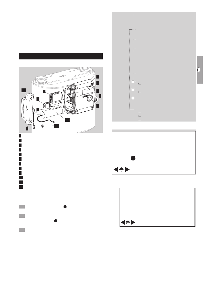
Service mode
Part designations
12
9
8
5
Electronic index EI3
Display
User keys
4 Opto-adapter interface
5 Service cover
6 Pulse output
7 Communication module
8 Battery for the index
9 Protection clip
0 Battery for the communication module
Installer seal
Connection for external antenna (option)
▷ In Service mode, meter-specific operating data
can be called up.
Activating Service mode
Hold the selection key
▷ A pixel will appear in each corner of the display.
Observe one pixel: while the pixel is visible, hold
the selection key pressed down. Release the
key as soon as the pixel has disappeared.
Repeat the process, until all the pixels are off and
“Test instructions” appears in the menu area.
▷ Service mode is activated.
Service mode menu overview
Main menu
Test instructions
Temperature
Pressure
Conversion
Battery diagnosis
1
2
1234 5678
BK-Gx
max
Q
min
Q
7
DE-07-MI002-PTB001
M07 0102
3
6
4
10
11
Test instructions
Date and time
–
LCD pixel test
–
Cyclic test
–
GPRS modem status
Identification & calibration info
Meter information
Calibration factors
Firmware traceability
Automatic return to main
menu after 5 minutes of
inactivity
Hold on any screen to
return immediately
Temperature
▷ The current gas temperature is displayed.
tg 25.00°C
TC : electronic
pressed down.
tg :[-25, 55]°C
tsp :20°C
tb :15°C
– tg currently measured gas temperature
– TC: type of temperature conversion
Electronic: mathematical conversion to tb
– tg: [ ] max. allowable gas temperature range
– tsp: specified centre temperature (in accordan-
– t
in index
tg [min. value, max. value]
ce with EN 1359)
: base temperature (in accordance with
b
EN1359), see page 14 (Technical data)
GB-5
Page 6

GB
F
NL
I
E
▷ Check test for temperature measurement, see
*Pressure
Conversion
Battery diagnosis
*
*Cyclic test: Starting
page 10 (Check test).
Pressure
▷ The current pressure data will be displayed.
Date and time
▷ Information on the date and time display.
Date and time
pg 1013.25mbar
PC :electronic
pg :[800.00, 1600.00]mbar
pb :1013.25mbar
– pg actual absolute gas pressure inside the
– PC: electronic – type of pressure conversion
– pg: [ ] max. allowable gas pressure range pg [min.
– pb: base pressure (in accordance with
meter
value, max. value]
EN1359)
▷
Check test for pressure measurement, see page
13 (Pressure test).
Conversion
▷ The conversion values are displayed.
Va 0000000.00m
3
Cf 00.9455660
pg 1013.25mbar
tg 25.00°C
Vb 0000000.00m
– Va volume alarm conditions
– Cf conversion factor Cf=
(p
/ pb) x (Tb / Tg) x (Zb / Z)
g
/ Z = 1
with Z
– pg actual absolute gas pressure inside the
– tg actual gas temperature
– Vb volume at base conditions
Battery diagnosis
▷ When the battery is connected, the status “OK”
is shown in the display.
b
meter
U(battery) 3.60 V
Status : OK
3
10–01–2011
10
:02:06
▷
The operator can transfer the switchover be-
tween winter and summer time to the communication module, provided that it supports this.
▷
The date is given in the format day - month - year.
▷
The date format can differ depending on the
market.
▷ This display is only visible if access to the past
meter readings has been activated.
LCD pixel test
▷ A display test can be carried out in this menu.
Follow the displayed instructions.
▷ A test pattern is shown in the display.
Briefly press the selection key
▷ A further test pattern appears in the display.
Hold the selection key pressed down. The display
switches to the previous menu.
Cyclic test
▷ The accuracy of the meter can be checked us-
ing a cyclic test.
C 000.00000
U 000.00000
tg 25.04°C
m
m
pg 1023.25mbar
N 00000-0 t 00000.00s
Press to abandon test
– C converted volume (temperature and
pressure)
– U non-converted volume
– tg gas temperature
– pg gas pressure (absolute)
– N number of complete measuring cycles
(measuring unit revolutions)– number of
intermediate sampling points in the measu-
ring cycle (max.8)
– t total testing time in seconds
Briefly press the selection key in order to start
the measurement. A beep confirms the start of
the measurement.
▷
The display is visible for the first 5minutes. It
then disappears but lights up every minute for
10seconds.
.
3
3
GB-6
Page 7

GB
F
NL
I
E
▷ In order to end the measurement, briefly press
GPRS modem status
ON
Meter information
Identification &
calibration info
Calibration information
Q1: 0.000m3/h CF1:16384
Q2: 6.000m
3
/h CF2:16384
Q3: 12.000m
3
/h CF3:16384
Meter information
the selection key
once the full number of measuring unit revolutions has been completed.
Measurement is terminated automatically after
▷
5hours.
▷ A beep indicates that measurement has ended.
Read off the measurement results.
▷ Check test for cyclic test, see page 10 (Check
test).
GPRS modem status
▷ The communication data are displayed.
again. Measurement stops
GSM.L : 100%
StCon : GPRS attached
GSM.N : Provider
IPAdr : 192.168.12.1
P.Sta : OK
– GSM.L: GSM reception level
The reception level between 1 – 31
– StCon: Connection status
GSM attached: comms module is
GSM not attached: comms module is
– GSM.N: GSM network operator
The name of the current provider is di-
– IPAdr: IP address is displayed
– P.Sta: PIN status: OK
PIN status: Failed
▷
▷
Identification & calibration info
Meter-specific technical data are displayed in submenus by pressing the user keys , and the
selection key .
is transferred to a percentage value
between 3 and 100%.
switched on
switched off
splayed in clear text.
For symbols, see page 3 (User keys, selection key and symbols).
Depending on the GPRS reception level (see
display), the use of an internal or an external
antenna is possible. The internal antenna is the
standard. In order to use an external antenna,
the service cover has to be exchanged by one
with an SMA connector.
Meter information
Version :1.xx.xx
CRC :0x0000
Details :REL 120727
Produced :2000
Meter information:
– Software version
– CRC: software checksum
– Software details
– Year of manufacture
▷ Other screen descriptions (not illustrated):
Calibration information:
– Meter calibration parameters Q1 to Q3
(adjustment values Q1 to Q3 for three-point
calibration)
Meter characteristics:
– Cyclic meter volume
– Transitional flow rate
– EN 1359 Reg. No.: NG-4701BM0443 (example)
Ambient conditions:
– Electromagnetic
– Mechanical
Firmware traceability
▷ The events shown are saved in the non-volatile
permanent log memory.
▷
The metrology-relevant system events, e.g. firm-
ware upgrades, restarts, low voltage, etc. are
stored in the permanent log memory.
▷
The events in the permanent log have unique
numbers, e.g.:
2 –> Firmware upgrade
15 –> Restart demand
16 –> Restart
▷ Only events which are relevant for the firmware
history are listed in the “Firmware traceability”
sub-menu.
Event: 2
Time: 12:18:45
Date: 12.06.2013
Info: 0xFFFFFFFFFFFF0104
6
Menu description
Event: event that has occurred; can be as-
signed the number 2, 15 or 16
Time: time at which the event occurred
4 Date: date on which the event occurred
5 Info: additional data, as explained below
6 Navigation symbols
1
2
3
4
5
GB-7
Page 8

GB
F
NL
I
E
In the case of event , “Firmware upgrade”, the
Event: 4
Time: 12:18:45
Date: 12.06.2013
Event: 4
Time: 12:18:45
Date: 12.06.2013
meaning of the additional data is as follows:
Info: 0xFFFFFFFFFFFF0104
Additional manufacturerspecific data
Reason:
00: upgrade started;
01: upgrade completed;
02: upgrade failed/error;
03: upgrade rejected
Establishing an optical communications link
▷ In order to configure the electronic index for the
respective application, the optical communications link must be activated.
Position the opto-adapter head on the interface
provided.
The user ID (HEX coded; here 0x04) means:
First position (1
information for the communication port:
0: unknown;
8: GSM modem;
9: opto-port.
Second position (2
a unique user ID 0 to F, e.g. 6 =>
manufacturer; further information is to be
requested from the meter owner.
In the case of event 5 “Restart demand” and
event 6 “Restart”, the meaning of the additional data is as explained below:
▷
The HEX values must always be itemized in pairs
(1byte).
▷ The HEX values of the firmware version are dis-
played “LSB first” coded.
▷ LSB first:least significant byte first.
▷ MSB first:most significant byte first.
Info: 0xXXXX 7DFE 1D150104
Additional manufacturerspecific data
Checksum (CRC), e.g.:
0x7DFE (MSB first coded)
Version information, e.g.:
0x1D1501 (display: LSB first)
=> 0x01151D (HEX, MSB first coded)
=> 01.21.29 (DEC, MSB first coded)
The user ID (HEX coded; here 0x04) means:
First position (1
information for the communication port:
0: unknown;
8: GSM modem;
9: opto-port.
Second position (2
a unique user ID 0 to F, e.g. 6 =>
manufacturer; further information is to be
requested from the meter owner.
st
nibble/here 0) contains the
nd
nibble/here 4) contains
st
nibble/here 0) contains the
nd
nibble/here 4) contains
Press any user key.
▷ Optical communication is enabled for 1 minute.
▷
If the optical communications link is not used
during this time, the interface will be deactivated.
Initiate communication.
▷ The procedure depends on your user software.
Setting the index parameters
▷
The index parameters can be adjusted using the
user equipment. Please contact manufacturer.
Replacing the communication module
WARNING
Risk of explosion in explosion-hazard areas!
– As a general rule, maintenance and repair work
should be avoided in explosive atmospheres.
– Check that the electrical system complies with
the special electrical explosion protection requirements.
– When working on electrical equipment in an
explosion-hazard area, only design-approved
electrical operating equipment may be used.
– Use original spare parts supplied by Elster
GmbH, see page 14 (Spare parts).
▷ When changing the SIM card together with the
communication module or just exchanging the
SIM card, the optical communications link has
to be established, see page 8 (Establishing
an optical communications link).
▷
For safe handling in an explosion-hazard area,
the order of the following steps has to be ensured.
GB-8
Page 9

GB
F
NL
I
E
Replacing the communication module
▷ TORX screw driver size T20 required.
31 2
4
7
5
8
6
9
0 Replace the service cover on the electronic index.
Push in a new screw locking cap, see page 14
(Spare parts). The body carrying out this task
should apply its own adhesive seal for sealing
the service cover.
Changing the SIM card
Establish the optical communications link, see
page 8 (Establishing an optical communications link).
Follow steps 1 to 6 of “Replacing the commu-
nication module”, see section above.
▷
The SIM card slot can be found on the underside
of the module.
Briefly press the SIM card to remove it from the
holder.
4 Insert the new SIM card in the same position
and lock it by pressing briefly.
5 To reinstall the communication module, follow
steps 7 to 11 of “Replacing the communication
module”, see section above.
▷ The new SIM card requires a new PIN number.
6 Enter the new PIN number via the optical in-
terface. The procedure depends on your user
software.
WARNING
Risk of losing data!
– Before changing the SIM card, ensure that the
GSM connection is not active!
Changing the battery
WARNING
Risk of explosion in explosion-hazard areas!
– As a general rule, maintenance and repair work
should be avoided in explosive atmospheres.
– Check that the electrical system complies with
the special electrical explosion protection re-
quirements.
– When working on electrical equipment in an
explosion-hazard area, only design-approved
electrical operating equipment may be used.
– Use original spare parts supplied by Elster
GmbH, see page 14 (Spare parts).
▷
The battery is available as a spare part, see
page14 (Spare parts).
▷ Prepare the index for changing the batteries.
▷ TORX screw driver size T20 required.
31 2
Battery for the communication module
▷ The battery can only be replaced when no data
communication is taking place (check for the RF
module symbol in the display). Otherwise, data
communication will be cut off.
Replace the battery as shown in the following steps:
5
7
8
0 Reprogram the battery parameters via the optical
interface.
▷ The procedure depends on your user software.
Replace the service cover on the electronic index.
Push in a new screw locking cap, see page 14
(Spare parts). The body carrying out this task
should apply its own adhesive seal for sealing
the service cover.
64
9
GB-9
Page 10

GB
F
NL
I
E
Electrical pulse output
WARNING
Risk of explosion in explosion-hazard areas!
– As a general rule, maintenance and repair work
should be avoided in explosive atmospheres.
– Check that the electrical system complies with
the special electrical explosion protection requirements.
– When working on electrical equipment in an
explosion-hazard area, only design-approved
electrical operating equipment may be used.
– This pulse output is not suitable for metrolo-
gical testing purposes, but for monitoring the
consumption.
▷ The generated pulses correspond to the values
shown in the technical data, see page 14
(Technical data).
▷
When gas consumption is higher than the output
can transmit its pulses, the pulses are buffered
and will be transmitted afterwards when con-
sumption is low.
Pin assignment:
Pin 1, 2, 4, 6: not connected
Pin 3: output +
Pin 5: output -
3
452
6
1
▷ To connect the pulse output, use a socket type
IEC 60130-9.
Check test
Directive 2014/32/EU (MID) prescribes that it must
be possible to check the meter.
▷
The requirements and test methods must comply
with national laws and regulations.
▷
The following tests describe the check tests
which are carried out by accredited testing
agencies.
▷
Always conduct a pressure and temperature
correction in accordance with established pro-
cedures (unit under test against master meter).
▷
Measurement accuracy class, see page 14
(Technical data).
▷
The unit under test must be acclimatized and
installed on the test rig.
▷
Maintain the climatic conditions constant dur-
ing the entire test duration. Otherwise, the test
results will be inaccurate.
▷ Immediately before commencing the test, pass
the quantity of test air, which corresponds to at
least 50times the cyclic volume of the unit under
test, through the meter at a flow rate of Q
(maximum flow rate of a gas meter).
max
▷
To conduct the tests, the thermowell and the
pressure test point (if available) can be used as
a reference for the temperature and pressure
measured by the index.
Cyclic test
The manual test is described below.
Legend
Δt
= total master meter testing time in s
N
ΔtP = testing time of the unit under test in s
Q
= maximum flow rate of a gas meter
max
Q
= minimum flow rate of a gas meter
min
QN = flow on master meter in m³/h based on
the displayed volume V
Q
= actual flow rate on master meter in m³/h
act,N
QP = flow determined on unit under test based
N
on VP in m³/h
VN = displayed volume on master meter in m³
V
= actual volume having flowed through the
act,N
master meter in m³
VP = displayed volume on unit under test in m³
Value after C or U in display, depending
on device configuration and test method.
See test procedure below for further
details.
FN = error of the master meter in %
FP = error of the unit under test in %
pN = absolute pressure on the master meter in
mbar
pP = absolute pressure on the unit under test in
mbar
TN = absolute temperature on the master meter
in K
TP = absolute temperature on the unit under
test in K
tb = base temperature in °C
Vb = converted volume with reference to tb and
p
pb = base pressure in mbar
b
Cyclic test at a constant flow rate
▷ The test rig is in pre-trial operation.
▷ Maintain the flow rate constant.
Test load and minimum test volumes for the test with
index readout:
Type
BK-G6 10 6 6 60 300
BK-G10 16 6 6 60 300
BK-G16 25 6 6 60 300
BK-G25 40 12 12 120 600
BK-G40 65 18 18 180 900
▷
Q
The minimum test volumes are recommended
max
in
m3/h
Cyclic
volume
in dm
Test volume in dm3 at
Q
0.2 Q
min
3
guide values. The measurement uncertainty of
the complete system (test rig plus unit under
test) must not exceed 1/3 of the maximum permissible error (MPE). The testing time must be
at least 10 s.
GB-10
maxQmax
Page 11

GB
F
NL
I
E
▷
In the test procedure described below, it is guaranteed that the unit under test always performs
full measuring unit rotations.
Master meter test procedure
Q
N
∆t
N
61
the master meter have already been taken into
account here:
FP = 100% x (((QP x pP x TN) / (Q
TP)) - 1)
act,N
x pN x
The following applies:
= (273.15 + {tg}) K
T
P
p
= {pg} mbar
P
in step 7 is determined from the non-con-
If Q
P
verted volume VP, the following applies:
TP = (273.15 + {tg}) K
where tg = relevant gas temperature on the unit
under test in °C (display)
▷ The curly brackets mean “numerical value of”.
▷
On a nozzle test rig with a known flow rate,
steps and 6 can be omitted.
▷
∆t
P
2 3 4 5
The error calculation is based on PTB Testing
Instructions, Volume 29: “Messgeräte für Gas –
Gaszähler” (Measuring instruments for gas – gas
meters), Edition 2003.
Set the test flow rate.
Start measuring the reference timeΔtN at mark-
er1.
Immediately afterwards, briefly press the selec-
tion key on the index to start the cyclic test
on the unit under test– marker2. The index will
thus be “armed” for measurement.
▷
As soon as one of the significant sensor posi-
tions has been detected, the unit changes to
measuring mode– marker3. A beep confirms
Cyclic test with a given volume
Test load and minimum test volumes for the test with
index readout:
Q
Cyclic
Type
BK-G6 10 6 180 360 360
BK-G10 16 6 180 360 360
BK-G16 25 6 180 360 360
BK-G25 40 12 360 720 720
BK-G40 65 18 540 1080 1080
max
in
m3/h
volume
in dm
Test volume in dm3 at
Q
min
3
0.2 Q
maxQmax
the start of the measurement.
▷
Once the required minimum testing time has
Master meter test procedure
been reached, the measurement can be terminated– marker4.
4 Briefly press the selection key in order to end
V
N
the measurement.
▷
Measurement on the unit under test stops automatically once the full number of measuring
unit revolutions has been completed– marker5.
8
10
▷ A beep acknowledges the end of the measure-
ment.
▷
Measurement is terminated automatically after
5 hours.
5 Stop the test on the master meter– marker6.
97
11
▷ The measurements are then available.
6 Read off the flow rate on the master meter or
calculate if necessary:
a) taking into account the inherent error of the
master meter:
Q
b) If the inherent error of the master meter has
= VN x 3600 s/h / ((1+FN/100) x ΔtN)
act,N
already been taken into account in the dis-
played volume (VN = V
Q
7 Calculate the flow rate on the unit under test:
8 The accuracy is checked by comparing the flow
= V
act,N
QP = VP/Δt
x 3600 s/h / Δt
act,N
P
act,N
):
N
rates. The pressure and temperature values of
the unit under test corrected with reference to
To activate the cyclic test on the unit under test,
briefly press the selection key on the index–
marker7. The index will thus be “armed” for
measurement.
Start the test on the master meter– marker8.
▷
As soon as one of the significant sensor positions has been detected, the unit changes to
measuring mode– marker9.
Test is ended– marker10.
4 Read off the test results on the unit under test.
▷
The measured values are updated with each 1/8
revolution of the measuring unit.
GB-11
Page 12

GB
F
NL
I
E
5 Compare the measurement results with the mas
ter meter and determine the measuring deviation
on the unit under test:
a) taking into account the inherent error of the
master meter:
FP = 100% x (((VP x (1+FN/100) x pP x TN) /
(V
x pN x TP)) - 1)
b) If the inherent error of the master meter has
N
already been taken into account in the displa-
yed volume (VN = V
FP = 100% x (((VP x pP x TN) / (V
T
)) - 1)
▷ The following applies:
T
pP = {pg} mbar
P
= (273.15 + {tg}) K
P
), the following applies:
act,N
act,N
x pN x
If the non-converted volume VP is taken for VP:
T
= (273.15 + {tg}) K
P
where t
= relevant gas temperature on the unit
g
under test in °C (display)
▷ The curly brackets mean “numerical value of”.
6 Stop execution of the cyclic test– marker 11.
Briefly press the selection key twice in order
to stop the measurement.
A beep confirms interruption of the measurement.
▷
▷
Measurement is terminated automatically after
5 hours.
▷
The error calculation is based on PTB Testing
Instructions, Volume 29: “Messgeräte für Gas –
Gaszähler” (Measuring instruments for gas – gas
meters), Edition 2003.
Pulse test (optical interface)
Test load and minimum test volumes for the test with
index readout:
Q
Cyclic
Type
BK-G6 10 6 180 360 360
BK-G10 16 6 180 360 360
BK-G16 25 6 180 360 360
BK-G25 40 12 360 720 720
BK-G40 65 18 540 1080 1080
▷ Pulse value V
▷ This test can only be carried out when the opti-
max
in
m3/h
volume
in dm
Imp
Test volume in dm3 at
Q
0.2 Q
min
3
maxQmax
, see page 14 (Technical data).
cal communications link has been established.
The procedure depends on your user software.
Establish the optical communications link, see
page 8 (Establishing an optical communications link).
Interrupt communication to the installed commu-
nication modules before starting the test so that
the measurement accuracy will not be adversely
affected.
-
Pulse test at a constant flow rate (optical
interface)
Master meter test procedure
Q
N
∆t
N
12
∆t
P
13 14
Set the test flow rate.
4 Start measuring the reference time ΔtN at mark-
er12.
▷ Marker12 indicates the release of the test flow
rate on the master meter.
5 Immediately afterwards, start the pulse test on
the unit under test– marker13.
▷ Then the unit under test generates the volume
pulses on the optical interface each time the
lowest-order decimal place on the meter display
is incremented– marker14. The test begins.
6 As soon as the required minimum test volume
has been reached on the unit under test, the
time measurement on the unit under test can
be stopped– marker15.
7 End the pulse test using any command– mark-
er16.
▷
Measurement is terminated automatically after
90minutes.
8 Shut off the gas flow to the master meter–
marker17.
9 Determine the volume on the unit under test VP:
VP = N x V
N = number of pulses during Δt
V
= pulse value V
Imp
nical data)
Imp
, see page 14 (Tech-
Imp
0 Calculate the flow rate on the unit under test:
QP = VP/Δt
Read off the flow rate on the master meter or
P
calculate if necessary:
a) taking into account the inherent error of the
master meter:
Q
b) If the inherent error of the master meter has
= VN x 3600 s/h / ((1+FN/100) x ΔtN)
act,N
already been taken into account in the displayed volume (VN = V
Q
act,N
= V
act,N
x 3600 s/h / Δt
act,N
):
17
15 16
P
N
GB-12
Page 13

GB
F
NL
I
E
The accuracy is checked by comparing the flow
rates. The pressure and temperature values of
the unit under test corrected with reference to
the master meter have already been taken into
account here:
FP = 100% x (((QP x pP x TN) / (Q
TP)) - 1)
act,N
x pN x
The following applies:
= (273.15 + {tg}) K
T
P
pP = {pg} mbar
▷ The curly brackets mean “numerical value of”.
▷
On a nozzle test rig with a known flow rate,
steps 4 and can be omitted.
▷
The error calculation is based on PTB Testing
Instructions, Volume 29: “Messgeräte für Gas –
Gaszähler” (Measuring instruments for gas – gas
meters), Edition 2003.
RTC test
▷
The climatic conditions must be maintained con-
stant at 22± 5°C during the entire test duration.
Temperature changes in 24hours ≤2K.
▷
Ensure that conditions remain sufficiently stable
during the measurement.
▷ The accuracy of the time count can be verified
with this test.
Acclimatize the unit under test and place next
to the time reference unit.
If necessary, activate the time display on both
units.
Ensure synchronous reading by taking a photo.
4 Observe a min. testing time of 72hours.
5 Repeat steps and .
6 The clock deviation of the unit under test must
not exceed the maximum admissible deviation. Maximum admissible deviation= 5ppm in
24hours.
Temperature test
▷ The accuracy of the temperature measurement
can be verified with this test.
▷ The temperature test can only be carried out in
Service mode.
CAUTION
To avoid damage to the meter:
– Comply with ambient temperature, see
page 14 (Technical data). Deviations from
the permitted ambient temperature will be recorded in the error memory.
▷ Temperature measurement accuracy, see page
14 (Technical data).
Install the diaphragm gas meter in a climatic
5 Select an ambient temperature as a reference
value and bring the climatic chamber to this temperature.
▷
To ensure there is also a uniform temperature
in the meter, we recommend starting the meter
air/gas flow during the temperature adjustment
phase.
▷
Ensure that temperature distribution remains
uniform and stable during the temperature
measurement.
6 Compare the measured value to the temperature
reference value.
If required, several reference values can be
▷
checked. In this case, repeat the test as of
point 5 .
Pressure test
▷
The accuracy of the pressure measurement can
be verified with this test.
▷
The pressure test can only be carried out in
Service mode.
CAUTION
To avoid damage to the meter:
– Comply with the maximum allowable operating
pressure, see page 15 (Technical data). Deviations from the permitted operating pressure will
be recorded in the error memory.
▷
Pressure measurement accuracy, see page
14 (Technical data).
▷
Keep the meter a sufficient time under stable
conditions to ensure acclimatization.
▷
Ensure stable conditions (temperature and pressure) during testing.
Close off the meter outlet connector so that it
is leak-tight, preferably with a valve to permit
venting.
Install a closed system with pressure pump and
reference pressure gauge at the inlet.
Slowly increase the pressure with the pressure
pump to the desired pressure.
4 Activate Service mode, see page 5 (Service
mode).
5 Change to the “Pressure” menu.
▷
The current pressure inside the meter housing
is displayed as absolute pressure.
6 Apply at least 5 minutes waiting time to ensure
pressure stabilization.
7 Compare the measured pressure value to the
pressure reference value.
8 Slowly open the outlet using the valve to prevent
meter damage.
chamber.
Activate Service mode– see page 5 (Service
mode).
Change to the “Cyclic test” menu.
▷ The current gas temperature is displayed.
4 Close the climatic chamber.
GB-13
Page 14

GB
F
NL
I
E
Assistance in the event of malfunction
? Fault
! Cause
• Remedy
Possible faults and suggested solutions
? The
! If the symbol appears next to a measured
• After the next time synchronization, the data are
? When pressing the user keys, the display
! Energy-saving mode is active. Due to excessive
• Leave the index unused for an extended period,
? When pressing the user keys, the display
! The index is defective.
• Contact the manufacturer.
symbol is displayed.
value, this means that the value is invalid.
recorded again correctly and disappears.
remains switched off. A beep can nevertheless be heard.
use of the index, the average energy consumption has been exceeded.
e.g. 24hours. After this, the user interface will
once again be available.
remains switched off and no beep can be
heard.
72910265, “Retrofit kit external antenna EI3 / 5m”
composed of:
– service cover -cpl. EA EI3 (32320088)
– PT screw K40x16 (03017232)
– GSM antenna L=5m (04271002)
Spare parts
Only the following spare parts are approved:
Communication module
Use only original Elster communication modules.
Elster Part No.:
72910267, “spare parts kit communication mod-
uleEI3” composed of:
– communication module GSM EI3 (32320046)
– PT screw K40x16 (03017232)
– screw locking cap EI (32447510)
Battery for the communication module
Use only original Elster batteries.
Elster Part No.:
72910266, “spare parts kit batterypack C.M. GSM
EI3” composed of:
– batterypack comm.module GSM EI3 (32447571)
– PT screw K40x16 (03017232)
– screw locking cap EI (32447510)
Screw locking cap
? The
symbol is displayed.
! Low index battery. This symbol is only displayed
when index battery power is low.
• Replace the index battery.
? Display light is off.
! Low index battery voltage.
• Replace the index battery.
! Display light is defective.
• Contact the manufacturer.
▷
In the case of faults which are not described here,
contact the manufacturer immediately.
Accessories
External antenna
Only the following antennas are approved as external
antennas.
Elster Part Nos.:
72910264, “Retrofit kit external antenna EI3 / 2.5m”
composed of:
– service cover -cpl. EA EI3 (32320088)
– PT screw K40x16 (03017232)
– GSM antenna L=2.5m (04271001)
Part No.: 32447510.
Technical data
RoHS compliant
Application with diaphragm gas meters BK..B
Enclosure: IP 65.
Maximum allowable operating pressure p
overpressure): see index plate,
base gas pressure pb: see index plate,
operating pressure range (absolute) pg:
800 to 1600mbar.
Life of battery for index: approx. 15 years.
Life of battery for communication module:
approx. 5 years.
Ambient temperature of index: -25 to +55°C (for
entire meter, see index plate).
Accuracy of the clock: 0.4 s/day at 20°C on the
day of manufacture.
Temperature measurement accuracy on the day of
manufacture:
± 0.2°C in the range from -10 to +55°C.
± 0.25°C in the range from -25 to -10°C.
Pressure measurement accuracy: ± 5 mbar on the
day of manufacture.
GB-14
max
(as
Page 15

GB
F
NL
I
E
Pulse value V
face:
Gas meter
BK-G6 3 1
BK-G10 – BK-G40 2 10
for pulse tests via optical inter-
Imp
Decimal
place
value V
in display
Pulse
in dm
Imp
3
The electrical interfaces feature the following
parameters:
Pulse output:
– U
= 26.6 V
i
= 250 mA
– I
i
– Pi = 414 mW
– C
= 0.012 µF
i
= 0 mH
– L
i
Communication module: GSM RF technology.
Data logger for past meter readings:
up to 20 weeks in hourly intervals.
Optical interface: pursuant to EN 62056-21,
Mode(E), Annex B.2.
Pulse output
Type of switch: open collector transistor, normally
closed.
For switching voltage and current, see section
“ATEX explosion protection” below.
Resolution: 1 pulse per 10 litres of base volume.
Maximum pulse frequency: 4 Hz.
For further technical data on diaphragm gas
meters BK, see:
“Operating instructions for diaphragm gas meters
BK-G1.6 to BK-G25” → http://docuthek.kromschroeder.com/doclib/main.php?language=1&folderi
d=400041&by_class=2&by_lang=-1
“Instruction Manual, Industrial Diaphragm Gas
Meters
Type BK-G40 · BK-G65 · BK-G100 and Type BK-
G40T · BK-G65T · BK-G100T” →
http://docuthek.
kromschroeder.com/doclib/main.php?language=1
&folderid=400045&by_class=2&by_lang=-1
Minimum pulse duration: 125 ms.
Logistics
For further technical data on diaphragm gas meters
BK, see:
“Operating instructions for diaphragm gas meters
BK-G1.6 to BK-G25” →
http://docuthek.kromschroeder.com/doclib/main.ph
p?language=1&folderid=400041&by_class=2&by_
lang=-1
“Instruction Manual, Industrial Diaphragm Gas Meters
Type BK-G40 · BK-G65 · BK-G100 and Type BK-G40T
· BK-G65T · BK-G100T” →
http://docuthek.kromschroeder.com/doclib/main.ph
p?language=1&folderid=400045&by_class=2&by_
lang=-1
ATEX explosion protection
The index EI3 is certified as an ATEX subassembly
and is marked as follows:
II 2 G Ex ib IIA T4 Gb
= Specific explosion protection mark
II = Equipment group for “non-mining”
2G = Equipment category 2 (zone 1) for gas
EX = Symbol for electrical equipment
built according to European standards
ib = Type of ignition protection:
i = intrinsically safe
b = suitable for use in zone 1
IIA = Explosion group for gases
T4 = Temperature class: maximum allowable
surface temperature: 135°C
Gb = Equipment protection level (zone 1)
The batteries and communication modules are
certified as parts of the electronic index. Use only
spare parts from Elster. For suitable batteries and
communication modules, see page 14 (Spare
parts).
Transport
Diaphragm gas meters are always to be transported
in the upright position. On receipt of the product,
check that the delivery is complete, see page 2
(Part designations). Report any transport damage
immediately.
Storage
Diaphragm gas meters are always to be stored in
the upright position and in a dry place. Ambient temperature: see page 14 (Technical data).
Disposal
Meters with electronic components:
Components, particularly batteries, are to be disposed of separately.
On request, old units may be returned carriage paid
to the manufacturer, see page 16 (Contact), in
accordance with the relevant waste legislation requirements.
GB-15
Page 16

GB
F
NL
I
E
Contact
Contact
United Kingdom
Elster Metering Limited
Paton Drive
Tollgate Business Park
Beaconside
Stafford, ST16 3EF
Tel. +44 1785 275200
Fax +44 1785 275305
jeavons.info@gb.elster.com
www.elstermetering.co.uk
Germany
Elster GmbH
Strotheweg 1
49504 Lotte
Tel. +49 541 1214-0
Fax +49 541 1214-370
info@elster-instromet.com
www.elster-instromet.com
Ireland
Active Energy Control Ltd.
Unit 4, Clare Marts
Quin Road
Ennis, Co. Clare
Tel. +353 65 6840600
Fax +353 65 6840610
info@aec.ie
www.aec.ie
GB-16
in the interests of progress.
We reserve the right to make technical modifications
 Loading...