

Page 1

GB
F
NL
I
SK
1000106001-002-06
03250952
D GB
I
➔ www.docuthek.com
Safety
Safety
Please read and keep in a safe place
Operating instructions for
operators and installers
Electronic index EI
© 2017 Elster GmbH · Edition 08.17
alpha
Translation from the German
Contents
Contents
Electronic index EI .....................
Contents ..............................
Safety.................................
Checking the usage .....................
Installation ............................
Operating the electronic index ............
Navigating within the menu ..............
Service mode ..........................5
Establishing an optical communications link 7
Changing the battery ....................7
Setting the index parameters .............8
Releasing the valve .....................8
Retrofitting/replacing the communication
module ...............................9
Check test.............................9
Assistance in the event of malfunction ....4
Spare parts ...........................4
Technical data ........................5
Logistics .............................5
Contact ..............................6
carefully before installing or operating. Following the
Please read through these instructions
installation, pass the instructions on to the operator. This unit must be installed and commissioned
in accordance with the regulations in force. These
instructions can also be found at www.docuthek.com.
Explanation of symbols
• , , , ... = Action
▷ = Instruction
Liability
We will not be held liable for damage resulting
from non-observance of the instructions and noncompliant use.
Safety instructions
Information that is relevant for safety is indicated in
the instructions as follows:
DANGER
Indicates potentially fatal situations.
WARNING
Indicates possible danger to life and limb.
CAUTION
Indicates possible material damage.
All interventions may only be carried out by qualified
gas technicians. Electrical interventions may only be
carried out by qualified electricians.
Conversion, spare parts
All technical changes are prohibited. Only use OEM
spare parts.
Changes to edition .
The following chapters have been changed:
– Checking the usage
– Logistics
GB-1
Page 2

GB
F
NL
I
SK
Checking the usage
*
Current meter reading
OFF
Electronic index EI.00, EI.05, EI.06,
EI. for diaphragm gas meters BK-G...E,
BK-G...ET or BK-G...ETe
Electronic index for reading out absolute meter readings and for retrieving consumption data, current
tariffs, messages and the valve position.
This function is only guaranteed when used within the
specified limits – see page 15 (Technical data). Any
other use is considered as non-compliant.
Type code
Code Description
EI Electronic index based on EI2
.00
.05
.06
.
Zigbee with valve Vs
Zigbee with valve Ve
Zigbee, valve Vs, top reading
Zigbee, valve Ve, top reading
Communication module
.00
.0
.0
▷
The index version is shown on the index plate,
ECM.10 (Zigbee SMETS 1)
ECM.02 (Zigbee)
see page 2 (Type label/Index plate).
When retrofitting or replacing the communication
▷
module, it may be the case that the last two characters in the type code are no longer applicable.
Part designations
Variant
None
ATEX
▷
The electronic index is suitable for use in potentially
explosive atmospheres. For the exact use (zone),
see ATEX sticker on the diaphragm gas meter or
see the operating instructions for diaphragm gas
meters BK-G1.6 to BK-G25 → http://docuthek.
kromschroeder.com/doclib/main.php?language
=1&folderid=400041&by_class=2&by_lang=-1.
Installation
Installing the gas meter
▷
For installing the gas meter in the pipework, refer
to the operating instructions for diaphragm gas
meters BK-G1.6 to BK-G25 → http://docuthek.
kromschroeder.com/doclib/main.php?language=1
&folderid=400041&by_class=2&by_lang=-1.
Gas meter with integrated valve
▷ If the integrated shut-off valve in the gas meter
is closed, it must be released, see page 8
(Releasing the valve).
Operating the electronic index
▷ The display on the index is switched off.
• Briefly press any key.
123 45678
BK-Gx
DE-07-MI002-PTB001
max
Q
min
Q
M07 0102
002545632734
5
6
Electronic index EI2
Display
User keys
4 Opto-adapter interface
5 Service cap
6 Installation seal/screw locking cap
Type label/Index plate
Please quote for all enquiries:
▷
Manufacturer’s serial number S/N (at the bottom left)
▷ Index version EI (next to the serial number)
V
p
S/N: ............ EI2. ...
BK-G..E..
Q
max
Q
min
max
M ... 0102
12345678
class 1,5
t
m
t
g
class 1,5
Valve Ve
1
2
3
▷ A beep sounds and the main screen appears.
▷
An internal buzzer gives audible feedback, e.g. a
short beep indicates a valve is open and a long
beep indicates a valve is closed. A short beep
sounds each time a key is pressed or if the unit
automatically changes back to the main screen.
▷
4
This function can be switched off, see page 8
(Setting the index parameters).
Main screen
1
3
00000.
ON
004
m
2
3
Menu area
Information area
Status line (symbols)
▷
The ON/
symbols are only displayed when
a valve is integrated in the gas meter.
GB-2
Page 3
GB
F
NL
I
SK
OFF
ON
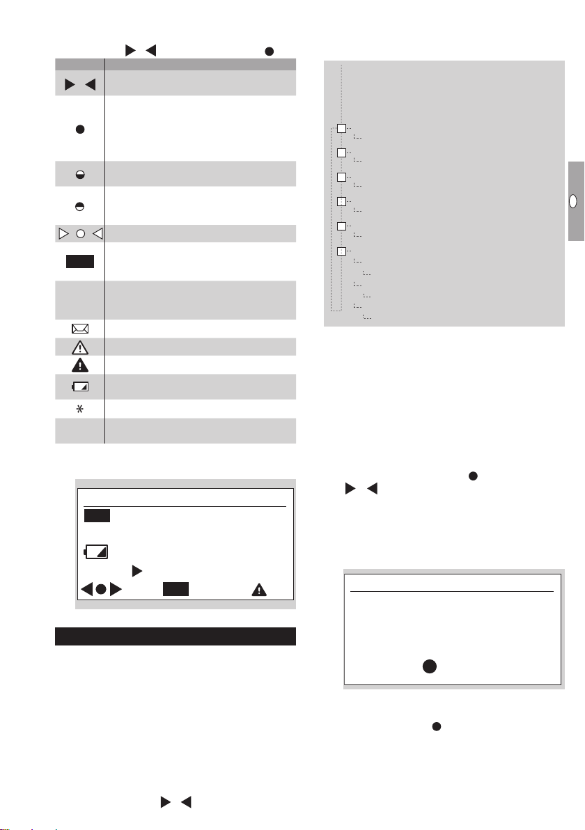
User keys, selection key and symbols
▷
You can navigate through the menu using the
user keys , and the selection key .
Symbol Meaning
▷
Navigate to the left or the right on each
,
level using the user keys.
Briefly pressing the selection key selects
a sub-menu.
Holding the selection key pressed down
switches the display back to the previous menu.
Briefly pressing the selection key selects
a sub-menu.
Holding the selection key pressed down
switches the display back to the previous menu.
Keys inactive
, ,
Valve/gas flow closed. This symbol is only
displayed when a valve is integrated in
the gas meter.
Valve/gas flow released. This symbol is
only displayed when a valve is integrated
in the gas meter.
New messages
Invalid data
Error message
Low battery. This symbol is only dis-
played when battery power is low.
Marking for metrology-relevant data
Substitute for undisplayable character
□
in sentence
In the “Icon definitions” menu, the most important
symbols are described briefly.
Icon denitions
OFF
Valve closed
Valve open
ON
Low battery
Press for more ...
OFF
Navigating within the menu
▷ The menu is constructed hierarchically.
▷
Depending on the configuration, some menus
may be missing.
▷
The “Current meter reading” main screen appears
when switching on the index.
▷
If you are in a different menu, the display will
automatically change back to the main screen
when no user key has been pressed for 30s,
and switches off after a further 30s.
You can navigate from the main screen to the
▷
various menus, such as “Meter information” using the user keys
, .
Menu overview
The display can differ depending on the parameteriza-
tion or communication module.
Main menu
–
Optional contents from communication module
–
Current meter reading
Icon definitions
–
Valve release procedure
–
Date and time
–
Historic meter readings
–
Meter information
Meter identification
Calibration information
Temperature conversion (optional)
Optional contents from communication
module
▷
For further information, refer to the operating
instructions for communication modules type
ECM (for electronic index).
Current meter reading
▷
The absolute meter reading and optionally the
current tariff are indicated in the main screen.
▷ This appears when switching on the index.
▷
You can receive information about the symbols by
pressing the selection key and the user keys
, , or see page 3 (User keys, selection
key and symbols).
Valve release procedure
▷ If the valve was released while the display was
switched off, the release note will appear the
next time the index is switched on.
Valve open safety check
CHECK IF
APPLIANCES OFF
HOLD FOR GAS
▷ The note remains active until the valve has been
released, see page8 (Releasing the valve).
▷
If the selection key is not pressed, the display
will switch back to the main screen after 30s.
GB-3
Page 4
GB
F
NL
I
SK
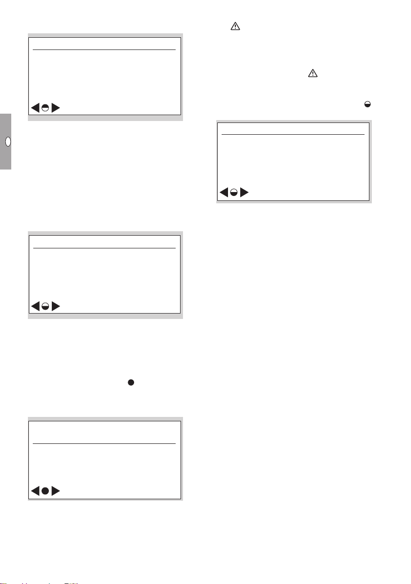
Date and time
*
Date and time
*
4 hour summary: Sat
▷ Information on the date and time display.
10–01–2011
10
:02:06
▷
The operator can transfer the switchover be-
tween winter and summer time to the communication module, provided that it supports this.
▷
The date is given in the format day - month - year.
▷
The date format can differ depending on the
market.
▷
This display is only visible if access to the historic
meter readings has been activated.
Historic meter readings
▷
Consumption data dating as far back as
60weeks can be called up.
Interval data
Historic
meter readings
ON
▷
The historic meter readings can be viewed as an
option. Depending on the parameterization, ac-
cess to the historic meter readings can either be
– fully activated or
– protected by entering a password or
– deactivated.
▷ By pressing the selection key , consumption
data are displayed, which are given by month,
week or day, or 4-hour or ½-hour intervals.
“4 hour summary” example:
Electronic index with communication module:
▷ The
Meter information
▷
symbol is displayed if, for example, the
tolerance between the internal time recording
and the actual time is too large. This can lead
to invalid consumption data. After the next time
synchronization, the consumption data are recorded again correctly and disappears.
Meter-specific technical data are displayed in
sub-menus by pressing the selection key
several times.
Meter information
Identification &
calibration info
ON
Meter identification:
– No.: (Owner’s meter number)
– EN 1359 Reg. No.: NG-4701BM0443 (exam-
ple)
– Firmware version
– CRC (checksum)
– Details (firmware details)
▷
For further information, see page 15 (Techni-
cal data).
Calibration information:
– Meter calibration parameters Q1 to Q3 (adjust-
ment values Q1 to Q3 for three-point calibration)
– Cyclic meter volume
Temperature conversion (optional):
– Type of conversion (mechanical or electronic)
– Base temperature tb (in accordance with
EN1359)
– Specified centre temperature tsp (in accordance
with EN1359)
01-02-2011 04:00 → 08:00
00000.351 → 00000.353m
0.002 m
▷
The timeframe is displayed with date and time
for the start and end of the period.
▷ The meter reading is displayed for the start and
end of the period in m
The consumption for this period is indicated in m3.
▷
▷ The tariff band may be displayed.
3
.
3
3
GB-4
Page 5
GB
F
NL
I
SK
Service mode
Test instructions
*
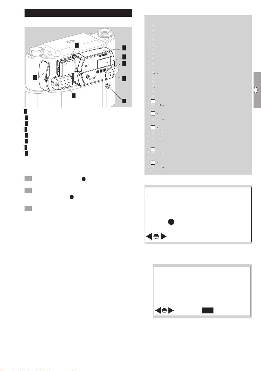
Part designations
Service mode menu overview
8
1234 5678
BK-Gx
DE-07-MI002-PTB001
max
Q
min
Q
M07 0102
002545632734
5
1
2
3
4
7
6
Electronic index EI2
Display
User keys
4 Opto-adapter interface
5 Service cover
6 Installation seal/screw locking cap
7 Battery
8 Communication module (optional)
▷ In Service mode, meter-specific operating data
can be called up.
Activating Service mode
Hold the selection key
pressed down.
▷ A pixel will appear in each corner of the display.
Observe one pixel: while the pixel is visible, hold
the selection key pressed down. Release the
key as soon as the pixel has disappeared.
Repeat the process, until all the pixels are off and
“Test instructions” appears in the menu area.
▷ Service mode is activated.
Main menu
Test instructions
Temperature (optional)
Battery diagnosis
Date & time
–
LCD pixel test
–
Cyclic test
–
UMI peripherals
UMI-1
UMI-2
UMI-3
–
Optional contents from communication module
–
Meter information
Test instructions
Automatic return to main
menu after 5 minutes of
inactivity
Hold on any screen to
return immediately
ON
Temperature (optional)
▷
This menu is available if temperature conversion
has been activated.
Temperature
tg 25.04°C
TC : electronic
tg : [-10, 40]°C
tsp : 20°C
tb : 0°C
OFF
– tg currently measured gas temperature t
– TC: type of temperature conversion
Electronic: mathematical conversion to tb
in index
Mechanical: mechanical conversion to t
in measuring unit
GB-5
g
b
Page 6

GB
F
NL
I
SK
– tg: [ ] max. allowable gas temperature range
OFF
Battery diagnosis
U(hlc) : 3.60 V
U(min) : 3.00 V
Status : OK
OFF
OFF
Battery diagnosis
U(hlc) : 3.60 V
U(min) : 3.00 V
Status : OK
Battery diagnosis
U(hlc) : 3.60 V
U(min) : 3.00 V
Status : Change required
Battery diagnosis
U(hlc) : 3.60 V
U(min) : 3.00 V
Status : Test in progress
Time : 05:00 h:m
*
Date and time
*
Cyclic test: Starting
– tsp: specified centre temperature tsp (in ac-
– tb: base temperature t
▷
▷
Battery diagnosis
▷ When the battery is connected, the status “OK”
t
[min. value, max. value]
g
cordance with EN 1359)
EN 1359), see page 15 (Technical data)
Check test for temperature test, see page 9
(Check test).
The measured value is updated once per minute.
is shown in the display.
(in accordance with
b
Battery diagnosis
U(hlc) : 3.60 V
U(min) : 3.00 V
Status : OK
OFF
– The U(hlc) value indicates the current voltage
measured on the battery or HLC.
– The U(min) value signals the minimum voltage
measured on the battery or HLC.
▷ If battery power is low, the display changes to
the status “Change required”. The battery must
be changed within a short time.
Battery diagnosis
U(hlc) : 3.60 V
U(min) : 3.00 V
Status : Change required
▷
Having disconnected the battery, the display
switches to the status “Removed”.
Battery diagnosis
U(hlc) : 3.60 V
U(min) : 3.00 V
Status : Removed
OFF
OFF
Date and time
▷ Information on the date and time display.
10–01–2011
10
:02:06
▷
The operator can transfer the switchover be-
tween winter and summer time to the communication module, provided that it supports this.
▷
The date is given in the format day - month - year.
▷
The date format can differ depending on the
market.
▷
This display is only visible if access to the historic
meter readings has been activated.
LCD pixel test
▷ A display test can be carried out in this menu.
Follow the displayed instructions.
▷ A test pattern is shown in the display.
Briefly press the selection key
▷ A further test pattern appears in the display.
Hold the selection key pressed down. The display
switches to the previous menu.
Cyclic test
▷ The accuracy of the meter can be checked us-
ing a cyclic test.
C 00.000000
U 00.000000
m
m
tg 25.04°C
N 00000-0 t 00000-0 s
Press to abandon test
– C = converted volume (temperature only)
for BK-G...E: no function (C = U)
for BK-G...ET: C = V
for BK-G...ETe: C = Vb, conversion to tb (see
page 15 (Technical data))
– U = non-converted volume V
for BK-G...ET: U = converted volume V
▷
The conversion takes place in the measuring unit.
– tg = measured gas temperature in °C
– N = number of complete measuring cycles
(measuring unit revolutions) – number of intermediate sampling points in the measuring cycle
(max. 8)
– t = total testing time in seconds
▷ for BK-G...ETe, the following applies:
The relationship between Vb and VP is as follows:
Vb = VP x Tb / T
GB-6
, conversion to tb = 15°C
b15
g
.
3
3
P
b15
Page 7

GB
F
NL
I
SK
where Tb = (273.15 + {tb}) K
ON
Meter information
Identification &
calibration info
Calibration information
Q1: 0.000m3/h CF1:16384
Q2: 6.000m
3
/h CF2:16384
Q3: 12.000m
3
/h CF3:16384
5
m
m
T
= (273.15 + {tg}) K
g
tb is specified in the technical data, see page
15 (Technical data).
▷ The curly brackets mean “numerical value of”.
For detailed information on the check test op-
▷
erating sequence, see page 9 (Check test).
UMI peripherals
▷
The status of the available interfaces for optional
communication modules is displayed.
Meter information
▷
Meter-specific technical data are displayed in
sub-menus by pressing the selection key and
the user keys , .
Meter information
Version :x.xx.xx
CRC :0x0000
Details :REL YYMMDD
Year of man. :YYYY
Meter information:
– Software version
– CRC: software checksum
– Software details
– Year of manufacture
▷ Other screen descriptions (not illustrated):
Calibration information:
– Meter calibration parameters Q1 to Q3 (adjust-
ment values Q1 to Q3 for three-point calibration)
Meter characteristics:
– Cyclic meter volume
– Transitional flow rate Q
– EN 1359 Reg. No.: NG-4701BM0443 (example)
Ambient conditions:
– Electromagnetic
– Mechanical
Establishing an optical communications link
▷ Depending on customer requirements, the opti-
cal interface can be locked.
▷ In order to configure the electronic index for the
respective application, the optical communications link must be activated.
Position the opto-adapter head on the interface
provided.
1234 5678
Press any user key.
▷ Optical communication is enabled for 1minute.
▷
If the optical communications link is not used
during this time, the interface will be deactivated.
Initiate communication.
▷ The procedure depends on your user software.
▷
For further information, refer to the operating
instructions for communication modules type
ECM (for electronic index).
Changing the battery
WARNING
Risk of explosion in explosion-hazard areas!
– As a general rule, maintenance and repair work
should be avoided in explosive atmospheres.
– Check that the electrical system complies with
the special electrical explosion protection requirements.
– When working on electrical equipment in an
explosion-hazard area, only design-approved
electrical operating equipment may be used.
– Use original spare parts supplied by Elster
GmbH, see page 14 (Spare parts).
▷ The battery is available as a spare part.
Prepare the index for changing the battery.
▷
The battery can only be replaced when the optical
communications link has been established, see
page 7 (Establishing an optical communica-
t
GB-7
tions link). Otherwise, data can be lost.
Start the battery change procedure.
▷ The procedure depends on your user software.
▷
Important! The battery may only be removed
once a release message has been issued by
the index. Otherwise, an integrated valve will be
closed and/or an error message will be transferred via the communication module.
▷ The index confirms disconnection of the battery
with a sound sequence.
Replace the battery as quickly as possible.
Q
Q
00254
▷
The index confirms connection of the battery
max
Q
min
Q
M07 0102
002545632734
with a sound sequence.
▷
The main screen appears when any key is
pressed.
▷ Optical communication is enabled for 1minute.
If the optical communications link is not used
during this time, the interface will be deactivated.
Page 8

GB
F
NL
I
SK
4 Reprogram the battery parameters.
ON
Valve open safety check
CHECK IF
APPLIANCES OFF
HOLD FOR GAS
Gas ow check complete
Gas flow check
successful
ON
OFF
Valve open safety check
CHECK IF
APPLIANCES OFF
HOLD FOR GAS
Opening valve
Please wait
Gas ow check complete
Gas flow check
successful
Gas flow check
failed
Gas ow check complete
▷ The procedure depends on your user software.
Electronic index without communication module:
▷ After the battery has been replaced, check the
time and update it if necessary. Note the global
UTC format.
5 Replace the service cover.
6 Push in a new screw locking cap, see page 14
(Spare parts). The body carrying out this task
should apply its own seal.
▷ After a short time, the unit switches to initializa-
tion mode.
Opening valve
Please wait
Setting the index parameters
The following index parameters can be adjusted using
the user software:
– properties of the historic values screen,
– time display,
– audible feedback when a key is pressed,
– parameters for valve release procedure.
Releasing the valve
▷
If a valve is integrated in the diaphragm gas
meter BK, this must be released/opened for
commissioning.
CAUTION
To avoid damage:
– Ensure the customer’s consumers are closed.
▷ The valve can only be released when the optical
communications link has been established or via
a communication module.
▷ Unless otherwise agreed, the valve is open on
delivery as standard.
▷ Once the valve has been released via the com-
munication module, this must be confirmed at
the meter on site by the consumer or another
person if applicable.
Establish the optical communications link, see
page 7 (Establishing an optical communications link).
Release the valve. The procedure depends on
your user software.
Valve open safety check
▷
After successful initialization, the gas flow check
is started. The test duration is shown in the display.
Gas ow check in progress
Max time:
Min time
▷
Once the release criteria have been checked,
the results are shown in the display.
Gas ow check complete
Gas flow check
successful
ON
00:29:56
:
00:06:08
CHECK IF
APPLIANCES OFF
HOLD FOR GAS
▷ The test procedure may differ from the descrip-
tion.
▷ Press the selection key and hold down.
GB-8
Page 9

GB
F
NL
I
SK
Retrofitting/replacing the
31 2
G
2
31 2
3
4
5
communication module
WARNING
Risk of explosion in explosion-hazard areas!
– As a general rule, maintenance and repair work
should be avoided in explosive atmospheres.
– Check that the electrical system complies with
the special electrical explosion protection re-
Replacing the communication module
Establish the optical communications link, see
page 7 (Establishing an optical communications link).
Deactivate the respective communication mod-
ule.
BK-
DE-07-MI00
max
Q
min
Q
M07 0102
002545632734
quirements.
– When working on electrical equipment in an
explosion-hazard area, only design-approved
electrical operating equipment may be used.
6
– The communication module may only be pulled
out if it has first been deactivated.
– When installing a communication module, en-
sure that the communication interface has been
deactivated.
– Further information can be found in the operat-
ing instructions for communication modules
type ECM (for electronic index).
– Use original spare parts supplied by Elster
GmbH, see page 14 (Spare parts).
▷
The communication module is available as a
spare part.
▷ The communication module can only be retrofit-
ted or replaced when the optical communications link has been established.
▷
The procedure differs depending on whether
the communication module is to be retrofitted
or replaced. See “Retrofitting the communication module” or “Replacing the communication
module”.
Retrofitting the communication module
▷
Check the status of the interface and deactivate
if necessary.
7 The communication module and index must be
paired.
▷ The procedure depends on your user software.
▷ Set the parameters of the communication mod-
ule according to the instructions or the servicing
steps provided by the relevant operator.
8 Replace the service cover.
9 Push in a new screw locking cap, see page 14
(Spare parts). The body carrying out this task
should apply its own seal.
Check test
Directive 2014/32/EU (MID) prescribes that it must
be possible to check the meter.
▷
The requirements and test methods must comply
with national laws and regulations.
▷
The following tests describe the check tests
which are carried out by accredited testing
agencies.
▷
Always conduct a pressure and temperature
correction in accordance with established procedures (unit under test against master meter).
▷
Measurement accuracy class, see page 15
(Technical data).
4 Establish the optical communications link, see
page 7 (Establishing an optical communications link).
▷ The intended interface for the optional commu-
nication module is UMI-1.
5 The communication module and index must be
paired.
▷ The procedure depends on your user software.
▷ Set the parameters of the communication mod-
ule according to the instructions or the servicing
steps provided by the relevant operator.
6 Replace the service cover.
7 Push in a new screw locking cap, see page 14
should apply its own seal.
(Spare parts). The body carrying out this task
▷
The unit under test must be acclimatized and
installed on the test rig.
▷
Maintain the climatic conditions constant during the entire test duration. Otherwise, the test
results will be inaccurate.
▷
Immediately before the beginning of the test, the
quantity of test air, which corresponds to at least
50x the cyclic volume of the meter to be tested,
is fed through the meter at a flow rate of Q
(maximum flow rate of a gas meter).
▷
During an active cyclic test, the display disappears after 5 minutes but lights up every minute for 10 seconds. This function is available for
max. 5 hours.
max
GB-9
Page 10

GB
F
NL
I
SK
▷
To conduct the tests, the thermowell and the
pressure test point (if available) can be used as
a reference for the temperature and pressure
measured by the meter.
Cyclic test
The cyclic test is designed for checking the meter
with a master meter. The recorded volume of the
unit under test during the testing period can be read
off directly from the index once the test has been
completed and can be compared with the master
meter. Testing at a constant flow rate thus ensures
the lowest possible level of measurement uncertainty
for the unit under test.
Legend
ΔtN = total master meter testing time in s
ΔtP = testing time of the unit under test in s
Q
= maximum flow rate of a gas meter
max
Q
= minimum flow rate of a gas meter
min
QN = flow on master meter in m³/h based on
the displayed volume V
Q
= actual flow rate on master meter in m³/h
act,N
QP = flow determined on unit under test based
N
on VP in m³/h
VN = displayed volume on master meter in m³
V
= actual volume having flowed through the
act,N
master meter in m³
VP = displayed volume on unit under test in m³
Value after C or U in display, depending
on device configuration and test method.
See test procedure below for further
details.
FN = error of the master meter in %
FP = error of the unit under test in %
pN = absolute pressure on the master meter in
mbar
pP = absolute pressure on the unit under test in
mbar
TN = absolute temperature on the master meter
in K
TP = absolute temperature on the unit under
test in K
tb = base temperature in °C
V
= converted volume with reference to
b15
Vb = converted volume with reference to t
There are two different options for carrying out the
tb=15°C
b
cyclic test:
Option : cyclic test at a constant flow rate
▷ The test rig is in pre-trial operation, i.e. start of
measurement on the unit under test will be delayed.
▷ Maintain the flow rate constant.
Test load and minimum test volumes for the test with
index readout:
Type
BK-G1.6 2.5 1.2 1.2 12 60
BK-G2.5 4.0 1.2 1.2 12 60
BK-G4 6.0 1.2 1.2 12 60
BK-G2.5 4.0 2 2 20 100
BK-G4 6.0 2 2 20 100
BK-G6 10 2 2 20 100
BK-G6 10 4 4 40 200
BK-G6 10 6 6 60 300
BK-G10 16 6 6 60 300
BK-G16 25 6 6 60 300
BK-G25 40 12 12 120 600
▷
Q
The minimum test volumes are recommended
max
in
m3/h
Cyclic
volume
in dm
Test volume in dm3 at
Q
0.2 Q
min
3
maxQmax
guide values. The measurement uncertainty of
the complete system (test rig plus unit under test)
must not exceed 1/3 of the maximum permissible error (MPE).
▷
The testing time must be at least 10s due to
the system design.
▷
In the test procedure described below, it is guaranteed that the unit under test always performs
full measuring unit rotations.
Master meter test procedure
Q
N
∆t
N
61
∆t
P
2 3 4 5
Set the test flow rate.
Start measuring the reference timeΔtN at mark-
er1.
Immediately afterwards, briefly press the selec-
tion key on the index to start the cyclic test
on the unit under test– marker2. The index will
thus be “armed” for measurement.
▷
As soon as one of the significant sensor positions has been detected, the unit changes to
measuring mode– marker3. A beep confirms
the start of the measurement.
GB-10
Page 11

GB
F
NL
I
SK
▷
Once the required minimum testing time has
been reached, the measurement can be terminated– marker4.
4 Briefly press the selection key in order to end
the measurement.
Measurement on the unit under test stops au-
▷
tomatically once the full number of measuring
unit revolutions has been completed– marker5.
▷ A beep acknowledges the end of the measure-
ment.
▷
Measurement is terminated automatically after
5 hours.
5 Stop the test on the master meter– marker6.
▷ The measurements are then available.
6 Read off the flow rate on the master meter or
Option : cyclic test with a given volume
Test load and minimum test volumes for the test with
index readout:
Cyclic
Q
max
Type
BK-G1.6 2.5 1.2 36 72 72
BK-G2.5 4.0 1.2 36 72 72
BK-G4 6.0 1.2 36 72 72
BK-G2.5 4.0 2 60 120 120
BK-G4 6.0 2 60 120 120
BK-G6 10 2 60 120 120
BK-G6 10 4 120 240 240
BK-G6 10 6 180 360 360
BK-G10 16 6 180 360 360
BK-G16 25 6 180 360 360
BK-G25 40 12 360 720 720
volume
in
3
/h
in dm
m
Test volume in dm3 at
Q
min
3
0.2 Q
maxQmax
calculate if necessary:
a) taking into account the inherent error of the
Master meter test procedure
master meter:
Q
b) If the inherent error of the master meter has
= VN x 3600 s/h / ((1+FN/100) x ΔtN)
act,N
V
N
already been taken into account in the dis-
played volume (VN = V
= V
Q
act,N
7 Calculate the flow rate on the unit under test:
x 3600 s/h / Δt
act,N
act,N
):
N
8
10
QP = VP/ΔtP
for BK-G...ET, the following applies: VP = V
8 The accuracy is checked by comparing the flow
rates. The pressure and temperature values of
the unit under test corrected with reference to
b15
97
11
the master meter have already been taken into
account here:
FP = 100% x (((QP x pP x TN) / (Q
The following applies:
x pN x TP)) - 1)
act,N
pP = relevant absolute pressure on the unit under
test
The following also applies:
for BK-G...E: T
where t
under test in °C (display)
= (273.15 + {tg}) K
P
= relevant gas temperature on the unit
g
for BK-G...ET: TP = (273.15 + {tb}) K
where tb = 15°C (see page 15 (Technical data)):
T
= 288.15 K
P
for BK-G...ETe:
in step 7 is determined from the converted
If Q
P
volume Vb, the following applies:
TP = (273.15 + {tb}) K (tb see page 15 (Techni-
cal data))
in step 7 is determined from the non-con-
If Q
P
verted volume VP, the following applies:
TP = (273.15 + {tg}) K
where tg = relevant gas temperature on the unit
under test in °C (display)
▷ The curly brackets mean “numerical value of”.
▷
On a nozzle test rig with a known flow rate,
steps and 6 can be omitted.
▷
The error calculation is based on PTB Testing
Instructions, Volume 29: “Messgeräte für Gas –
meters), Edition 2003.
Gaszähler” (Measuring instruments for gas – gas
To activate the cyclic test on the unit under test,
briefly press the selection key on the index–
marker7. The index will thus be “armed” for
measurement.
Start the test on the master meter– marker8.
▷
As soon as one of the significant sensor positions has been detected, the unit changes to
measuring mode– marker9.
Test is ended– marker10.
4 Read off the test results on the unit under test.
▷
The measured values are updated with each 1/8
revolution of the measuring unit.
5 Compare the measurement results with the mas
ter meter and determine the measuring deviation
on the unit under test:
a) taking into account the inherent error of the
master meter:
FP = 100% x (((VP x (1+FN/100) x pP x TN) /
(VN x pN x TP)) - 1)
b) If the inherent error of the master meter has al-
ready been taken into account in the displayed
volume (VN = V
FP = 100% x (((VP x pP x TN) / (V
TP)) - 1)
▷
The following applies: pP = relevant absolute
), the following applies:
act,N
act,N
x pN x
pressure on the unit under test
-
GB-11
Page 12

GB
F
NL
I
SK
▷ The following also applies:
for BK-G…E: T
where t
g
under test in °C (display)
= (273.15 + {tg}) K
P
= relevant gas temperature on the unit
for BK-G...ET: TP = (273.15 + {tb}) K
where tb = 15°C (see page 15 (Technical data)):
T
= 288.15 K
P
for BK-G…ETe:
If the converted volume V
TP = (273.15 + {tb}) K (tb see page 15 (Techni-
is taken for VP:
b
cal data))
If the non-converted volume V
= (273.15 + {tg}) K
T
P
where tg = relevant gas temperature on the unit
is taken for VP:
P
under test in °C (display)
▷ The curly brackets mean “numerical value of”.
6 Stop execution of the cyclic test– marker 11.
Briefly press the selection key twice in order
to stop the measurement.
▷
A beep confirms interruption of the measurement.
▷
Measurement is terminated automatically after
5 hours.
The error calculation is based on PTB Testing
▷
Instructions, Volume 29: “Messgeräte für Gas –
Gaszähler” (Measuring instruments for gas – gas
meters), Edition 2003.
Pulse test
The pulse test is designed for checking the meter with
a master meter. The recorded volume is provided by
pulses which are emitted via the optical interface.
Test load and minimum test volumes for the test with
index readout:
Q
Cyclic
Type
BK-G1.6 2.5 1.2 36 72 72
BK-G2.5 4.0 1.2 36 72 72
BK-G4 6.0 1.2 36 72 72
BK-G2.5 4.0 2 60 120 120
BK-G4 6.0 2 60 120 120
BK-G6 10 2 60 120 120
BK-G6 10 4 120 240 240
BK-G6 10 6 180 360 360
BK-G10 16 6 180 360 360
BK-G16 25 6 180 360 360
BK-G25 40 12 360 720 720
▷ Pulse value V
▷ This test can only be carried out when the opti-
max
in
m3/h
volume
in dm
Imp
Test volume in dm3 at
Q
0.2 Q
min
3
maxQmax
, see page 15 (Technical data).
cal communications link has been established.
The procedure depends on your user software.
Establish the optical communications link, see
page7 (Establishing an optical communications link).
Interrupt communication to the installed commu-
nication modules before starting the test so that
the measurement accuracy will not be adversely
affected.
As of step 3, continue as described in one of the two
following sections.
Pulse test at a constant flow rate (optical
interface)
Master meter test procedure
Q
N
∆t
N
12
∆t
P
13 14
17
15 16
Set the test flow rate.
4 Start measuring the reference time ∆tN at mark-
er12.
▷ Marker12 indicates the release of the test flow
rate on the master meter.
5 Immediately afterwards, start the pulse test on
the unit under test– marker13.
▷ Then the unit under test generates the volume
pulses on the optical interface each time the
lowest-order decimal place on the meter display
is incremented– marker14. The test begins.
6 As soon as the required minimum test volume
has been reached on the unit under test, the
time measurement on the unit under test can
be stopped– marker15.
7 End the pulse test using any command– mark-
er16.
▷
Measurement is terminated automatically after
90minutes.
8 Shut off the gas flow to the master meter–
marker17.
9 Determine the volume on the unit under test VP:
VP = N x V
N = number of pulses during Δt
V
= pulse value V
Imp
Imp
cal data)
, see page 15 (Techni-
Imp
P
0 Calculate the flow rate on the unit under test:
QP = VP/Δt
Read off the flow rate on the master meter or
P
calculate if necessary:
a) taking into account the inherent error of the
master meter:
Q
b) If the inherent error of the master meter has
= VN x 3600 s/h / ((1+FN/100) x ΔtN)
act,N
already been taken into account in the dis-
played volume (VN = V
Q
act,N
= V
x 3600 s/h / Δt
act,N
act,N
):
N
GB-12
Page 13

GB
F
NL
I
SK
The accuracy is checked by comparing the flow
rates. The pressure and temperature values of
the unit under test corrected with reference to
the master meter have already been taken into
account here:
FP = 100% x (((QP x pP x TN) / (Q
TP)) - 1)
act,N
x pN x
The following applies:
pP = relevant absolute pressure on the unit under test
The following also applies:
for BK-G...E: TP = (273.15 + {tg}) K
where t
= relevant gas temperature on the unit
g
under test in °C (display)
for BK-G...ET and BK-G...ETe:
TP = (273.15 + {tb}) K (tb see page 15 (Techni-
cal data))
▷ The curly brackets mean “numerical value of”.
▷
On a nozzle test rig with a known flow rate,
step 4 can be omitted.
▷
The error calculation is based on PTB Testing
Instructions, Volume 29: “Messgeräte für Gas –
Gaszähler” (Measuring instruments for gas – gas
meters), Edition 2003.
Recommission the previously switched off com-
munication modules.
Pulse test with a given volume
Master meter test procedure
V
N
19
18 21
20
Start the pulse test on the unit under test–
marker18.
4 Start the test on the master meter– marker19.
5 Record the pulses from the unit under test.
▷
The unit under test generates the volume pulses
on the optical interface each time the lowest-
order decimal place on the index display is in-
cremented.
6 The test volume is achieved and the test ends–
marker20.
7 End the pulse test on the unit under test using
any command– marker21.
▷
Measurement is terminated automatically after
90minutes.
8 Determine the volume on the unit under test VP:
V
= N x V
P
N = number of pulses
V
= pulse value in m³
Imp
9 Read off the volume on the unit under test.
Imp
The inherent error of the master meter is to be
taken into account if applicable:
V
0 Determine the measuring deviation on the unit
= VN / (1 + FN/100)
act,N
under test:
FP = 100% x (((VP x pP x TN) / (V
▷
The pressure and temperature values of the unit
x pN x TP)) - 1)
act,N
under test corrected with reference to the master
meter have already been taken into account here.
The following applies:
pP = relevant absolute pressure on the unit under
test
The following also applies:
for BK-G…E: T
where tg = relevant gas temperature on the unit
= (273.15 + {tg}) K
P
under test in °C (display)
for BK-G…ET and BK-G…ETe:
TP = (273.15 + {tb}) K (tb see page15 (Techni-
cal data))
▷ The curly brackets mean “numerical value of”.
▷
The error calculation is based on PTB Testing
Instructions, Volume 29: “Messgeräte für Gas –
Gaszähler” (Measuring instruments for gas – gas
meters), Edition 2003.
Recommission the previously switched off com-
munication modules.)
RTC test
▷
The climatic conditions must be maintained con-
stant at 22± 5°C during the entire test duration.
Temperature changes in 24hours ≤2K.
▷
Ensure that conditions remain sufficiently stable
during the measurement.
▷ The accuracy of the time count can be verified
with this test.
Acclimatize the unit under test and place next
to the time reference unit.
If necessary, activate the time display on both
units.
Ensure synchronous reading by taking a photo.
4 Observe a min. testing time of 24hours.
5 Repeat steps and .
6 The clock deviation of the unit under test must
not exceed the maximum admissible deviation.
Maximum admissible deviation= 100ppm in
24hours.
GB-13
Page 14

GB
F
NL
I
SK
Temperature test
▷
A temperature test is required on diaphragm gas
meters with temperature conversionBK..Te only.
▷ The accuracy of the temperature measurement
can be verified with this test.
▷ The temperature test can only be carried out in
Service mode.
CAUTION
To avoid damage to the unit:
– Comply with ambient temperature, see
page 15 (Technical data). Deviations from
the permitted ambient temperature will be recorded in the error memory.
▷
Temperature measurement accuracy, see
page15 (Technical data).
Install the diaphragm gas meter in a climatic
chamber.
Activate Service mode– see page 5 (Service
mode).
Change to the “Temperature” menu.
▷ The current gas temperature is displayed.
4 Close the climatic chamber.
5 Select an ambient temperature as a reference
value and bring the climatic chamber to this temperature.
▷
To ensure there is also a uniform temperature
in the meter, we recommend starting the meter
air/gas flow during the temperature adjustment
phase.
▷
Ensure that temperature distribution remains
uniform and stable during the temperature
measurement.
6 Compare the measured value to the temperature
reference value.
▷
If required, several reference values can be
checked. In this case, repeat the test as of
point 5 .
• Leave the index unused for an extended period,
e.g. 24hours. After this, the user interface will
once again be available.
? When pressing the user keys, the display
remains switched off and no beep can be
heard.
! The index is defective.
• Contact the manufacturer.
? The
symbol is displayed.
! Low battery. This symbol is only displayed when
battery power is low.
• Replace the battery.
▷
In the case of faults which are not described here,
contact the manufacturer immediately.
Spare parts
Battery
For meters without communication module:
Elster Part No.: 32906520.
For meters with communication module:
Elster Part No.: 72910321.
Communication module
Use ATEX compliant communication modules only.
A safety sticker with the following code must be
attached to the communication module:
II 3G Ex ic IIA Gc (-25°C ≤ Ta ≤ +55°C).
Electrical connection parameters, see page 15
(Technical data).
Screw locking cap
Assistance in the event of malfunction
? Fault
! Cause
• Remedy
Possible faults and suggested solutions
? The
! If the symbol appears next to a measured
• After the next data synchronization, the data are
? When pressing the user keys, the backlight-
! Energy-saving mode is active. Due to excessive
symbol is displayed.
value, this means that the value is invalid.
recorded again correctly and disappears.
ing and/or display remain switched off. A
beep can nevertheless be heard.
use of the index, the average energy consumption has been exceeded.
Elster Part No.: 32447510.
GB-14
Page 15

GB
F
NL
I
SK
Technical data
Application with diaphragm gas meters BK..E
RoHS compliant
Enclosure: IP 54.
Battery life: approx. 10years.
Maximum allowable ambient temperature range: see
type label/index plate.
Data logger for historic meter readings:
up to 60weeks in 30-minute intervals.
Optical interface: pursuant to EN62056-21, Mode(E),
AnnexB.2.
Accuracy of the clock: 0.4 s/day at 20°C on the day
of manufacture.
Diaphragm gas meter BK..ETe with temperature
conversion:
Temperature measurement accuracy: ± 1°C on the
day of manufacture.
The base temperature tb is specified on the index
plate.
Pulse output of optical interface
Pulse value V
Gas meter
BK-G 1.6 – BK-G 6 3 1
BK-G 10 – BK-G 25 2 10
Pulse duration: 90 ms
For further technical data on diaphragm gas meters
BK– see the operating instructions for diaphragm
gas meters BK-G1.6 to BK-G25 → http://docuthek.
kromschroeder.com/doclib/main.php?language=1&
folderid=400041&by_class=2&by_lang=-1.
Imp
:
Decimal
place
in display
Pulse
value V
in dm
Imp
3
Logistics
Transport
Diaphragm gas meters are always to be transported
in the upright position. On receipt of the product,
check that the delivery is complete, see page 2
(Part designations). Report any transport damage
immediately.
Storage
Diaphragm gas meters are always to be stored in
the upright position and in a dry place. Ambient temperature: see page 15 (Technical data).
Disposal
Meters with electronic components:
Components, particularly batteries, are to be disposed of separately.
On request, old units may be returned carriage paid
to the manufacturer, see page 16 (Contact), in
accordance with the relevant waste legislation requirements.
ATEX explosion protection
Battery
Only use approved batteries from Elster.
The “Battery pack cpl. EI2” is certified as part of the
electronic index.
Communication modules
Please contact the manufacturer for details on suitable communication modules. Information on the
ATEX suitability can be found in the operating instructions of the respective communication module.
The UMI interface features the following parameters:
– UO = 3.9 V peak, 3.6 V nominal,
– IO = 7.5 A peak, 506 mA nominal,
– PO = 1.55 W,
– CO = 12 µF,
– LO = 50 nH.
For more data on explosion protection of diaphragm
gas meters BK– see the operating instructions for
diaphragm gas meters BK-G1.6 to BK-G25 → http://
uage=1&folderid=400041&by_class=2&by_lang=-1.
docuthek.kromschroeder.com/doclib/main.php?lang
GB-15
Page 16

GB
F
NL
I
SK
Contact
Contact
United Kingdom
Elster Metering Limited
Paton Drive
Tollgate Business Park
Beaconside
Stafford, ST16 3EF
Tel. +44 1785 275200
Fax +44 1785 275305
jeavons.info@gb.elster.com
www.elstermetering.co.uk
Germany
Elster GmbH
Strotheweg 1
49504 Lotte
Tel. +49 541 1214-0
Fax +49 541 1214-370
info@elster-instromet.com
www.elster-instromet.com
Ireland
Active Energy Control Ltd.
Unit 4, Clare Marts
Quin Road
Ennis, Co. Clare
Tel. +353 65 6840600
Fax +353 65 6840610
info@aec.ie
www.aec.ie
GB-16
in the interests of progress.
We reserve the right to make technical modifications
 Loading...