

Honeywell EGPWS MK V, EGPWS MK VII Pilot's Manual

FILE ONLY - Release - 08 Aug 2011 14:50:02 MST - Printed on 01 Mar 2013


NOTE
The enclosed technical data is eligible for export under License
Designation NLR and is to be used solely by the individual/organization
to whom it is addressed. Diversion contrary to U.S. law is prohibited.
COPYRIGHT NOTICE
Copyright © 2011 Honeywell International Inc. All rights reserved.
All marks are owned by their respective companies.
Reproduction of this publication or any portion thereof by any means without
the express written permission of Honeywell International Inc. is prohibited.
For further information, contact Airlines and Avionics Products (AAP):
Address: 15001 N.E. 36th Street, Redmond, WA 98073
Telephone: 425-885-8367
OR
Honeywell Global Customer Care
Telephone: 800-601-3099 (U.S.A./Canada)
Telephone: 602-365-3099 (International)
Web site: http://portal.honeywell.com/wps/portal/aero
The information contained in t his manual is for re feren ce us e only.
If any information contained herein conflicts with similar information
contained in the Airplane Flight Manual, the information in the Airplane
Flight Manual shall take precedence.


Mark V and Mark VII EGPWS Pilot’s Guide
060-4241-000 Table of Contents
Rev H, August 2011 i
TABLE OF CONTENTS
SECTION 1 INTRODUCTION ................................................................ 1
SECTION 2 SYSTEM DESCRIPTION .................................................... 5
SECTION 3 OPERATIONAL PROCEDURES ...................................... 46
SECTION 4 DEFINITIONS .................................................................... 59
SMARTRUNWAY® PILOT GUIDE ...................................................... 61
SMARTLANDINGTM PILOT GUIDE .................................................... 99
Request for Information ........................................................................ 117

Mark V and Mark VII EGPWS Pilot’s Guide
Table of Contents 060-4241-000
ii Rev H, August 2011
Blank Page

Mark V and Mark VII EGPWS Pilot’s Guide
060-4241-000 Introduction
Rev H, August 2011 1
SECTION 1 INTRODUCTION
This Pilot Guide describes the functions and operation of the
MK V and MK VII Enhanced Ground Proximity Warning
System (EGPWS).
The document is divided into four sections:
Section 1 is this introduction and the following brief
description of the EGPWS and its features.
Section 2 provides a functional description of the EGPWS.
This includes descriptions of the various system modes;
Built-In-
Test (BIT) and monitoring functions, and system
features.
Section 3 provides general operating procedures to follow
when the system gives a caution or warning alert.
Section 4 provides definitions of terms used in this manual.
This guide does not supersede FAA approved data, Flight
Manuals, individual Operations Manuals, requirements,
or procedures. Pilots should be thoroughly familiar with
their own company policies, system configuration,
requirements, and procedures with respect to the
operation of the aircraft with the EGPWS.
The information in this document is intended as a general
explanation of the Honeywell EGPWS. It contains a general
description of system performance assuming identified
options are active, and highlights deviations in system
performance resulting when a feature is disabled.
What is the
EGPWS?
The EGPWS is a Terrain Awareness and Alerting system
providi
ng terrain alerting and display functions with
additional f eatures meeting the requirements of TSO C151b
Class A TAWS.
The EGPWS uses aircraft inputs including geographic
position, attitude, altitude, airspeed, and glideslope deviation.
These are used with internal terrain, obstacles, and airport
runway datab ases to predict a potential conflict between the
aircraft flight path and terrain or an obstacle. A terrain or
obstacle conflict results in the EGPWS providing a visual
and audio caution or warning alert.
Additionally, the EGPWS provides alerts for excessive
glideslope deviation, too low with flaps or gear not in
landing configuration, and optionally provides bank angle
and altitude callouts based on system program pin selection.
Detection of severe windshear conditions is also provided for
selected aircraft types when enabled.

Mark V and Mark VII EGPWS Pilot’s Guide
Introduction 060-4241-000
2 Rev H, August 2011
What is the
EGPWS?
Continued
The EGPWS incorporates several “enhanced” features:
• Terrain Alerting and Display (TAD) provides a graphic
display of the surrounding terrain on the Weather Radar
Indicator, EFIS, or a dedicated display. Based on the
aircraft’s position and the internal database, the terrain
topography (within the display range selected) that is
above or within 2000 feet below the aircraft altitude is
presented on the system display. This feature is an option,
enabled by program pins during installation.
• “Peaks” is a TAD supplemental feature providing
additional terrain display features for enhanced situational
awareness, independent of the aircraft’s altitude. This
includes digital elevations for the highest and lowest
displayed terrain, additional elevation (color) bands, and a
unique representation of 0 MSL elevation (sea level and
its corresponding shoreline). This feature is an option,
enabled by program pins during installation.
• “Obstacles” is a feature utilizing a database of man-made
objects for obstacle conflict alerting
and display.
Additionally, when TAD is enabled, Obstacles are
graphically displayed similar to terrain. This feature is an
option, enabled by program pins during installation.
• Envelope Modulation is a feature u tilizing a database of
airport approach and departure profiles to tailor EGPWS
alerts at certain geographic locations to reduce nuisance
alerts and provide added protection.
• A Terrain Clearance Floor (TCF) feature adds an
additional element of protection by alerting the pilot of
possible premature descent. This is intended for nonprecision approaches and is based on the current aircraft
position relative to the nearest runway. This feature is
enabled with the TAD feature.
• The Runway Field Clearance Floor (RFCF) feature is
circular band similar to the TCF feature except that RFC F
is based on the current aircraft position and height above
the destination runway based on Geometric Altitude (see
n
ext page) and only extends 5 NM past the end of the
runway.
This provides improved protection at locations
where the destination runway is significantly higher than
the surrounding terrain. (In -210-210 and later versions).
• An Aural Declutter feature reduces the repetition of
warning messages. This feature is optional, and may be
disabled by system program pins during installation.

Mark V and Mark VII EGPWS Pilot’s Guide
060-4241-000 Introduction
Rev H, August 2011 3
What is the
EGPWS?
Continued
• Geometric Altitude, based on GPS altitude, is a
computed pseudo-barometric altitude designed to reduce
or eliminate altitude errors resulting from temperature
extremes, nonstandard pressure altitude conditions, and
altimeter miss-
sets. This ensures an optimal EGPWS
alerting and display capability.
• The Runway Awareness & Advisory System (RAAS)
option provides alerts and advisories that increase crew
situational awareness during operations on and around
airports. This feature is an option, enabled by PCMCIA
card, available in -218-218 or later versions.
• The SMARTRUNWAY
®
option provides alerts and
advisories that increase crew situational awareness du ring
operations on and around airports; combining the RAAS
functions with added improvements for Taxiway Landing,
Taxiway Takeoff, Short Runway Cautions, Visual
Messaging, and Takeoff Flap Monitor (incorrect takeoff
flap configuration). These features are optional, enabled
by PCMCIA card, available in -230-230 or later versions.
• The SMARTLANDINGTM option provides visual and aural
annunciations that supplement flight crew awareness of
un-stabilized approaches, altimeter setting problems,
landing long and select RAAS ad visories. These features
are optional, enabled b y PCMCIA card, available in -230230 or later versions.
Physical
Description
Some of these features have been added to the EGPWS as
the system evolved and are not present in all Enhanced
Ground Proximity Warning Computer (EGPWC) part
numbers. For specific effectivity, refer to an applicable
Airplane Flight Manual (AFM) or EGPWS Airplane Flight
Manual Supplement (AFMS) or contact Honeywell for
assistance.
The EGPWC is packaged in a 2 MCU ARINC 600-6 rack
mounted enclosure weighing less than 8 lbs. No special
vibration isolation mounting or forced air-
cooling is
required.
115 VAC (400 Hz.) or 28 VDC versions of the EGPWC are
available. Units are also available with an internal GPS
receiver for required GPS data when anoth er GPS source is
not available.
For more detailed descriptions and information, contact
Honeywell.

Mark V and Mark VII EGPWS Pilot’s Guide
Introduction 060-4241-000
4 Rev H, August 2011
Blank Page

Mark V and Mark VII EGPWS Pilot’s Guide
060-4241-000 System Description
Rev H, August 2011 5
SECTION 2
SYSTEM DESCRIPTION
Enhanced Ground P r o ximity Warning S ystem ............................................... 6
EGPWS Database ................................................................................................ 6
Basic F unc tions:
Mode 1 - Excessive Descent Rate ........................................................................ 8
Mode 2 - Excessive Closure to Terrain ................................................................ 9
Mode 2A .............................................................................................................. 9
Mode 2B ............................................................................................................ 11
Mode 3 - Altitude Loss After Takeoff ............................................................... 13
Mode 4 - Unsafe Terrain Clearance ................................................................... 14
Mode 4A ............................................................................................................ 14
Mode 4B ............................................................................................................ 15
Mode 4C ............................................................................................................ 16
Mode 5 - Excessive Deviation Below Glideslope .............................................. 18
Mode 6 - Advisory Callouts ............................................................................... 19
Mode 7 - Windshear Alerting ............................................................................. 24
Enhanced Functi ons:
Envelope Modulation ......................................................................................... 26
Terrain Clearance Floor ..................................................................................... 26
Runway Field Clearance Floor .......................................................................... 28
Terrain Look Ahead Alerting ............................................................................ 29
Terrain Alerting and Display ............................................................................. 30
Non-Peaks Display ............................................................................................ 30
Pop-Up and Auto-Range .................................................................................... 33
Peaks Display .................................................................................................... 33
TAD/TCF INOP Annunciator and INHIBIT ....................................................... 37
Geometric Altitude ............................................................................................ 37
Weather Radar Auto-Tilt ................................................................................... 38
Aural Message Priority ...................................................................................... 38
System Inputs ................................................................................................... 40
System Outputs ................................................................................................ 42
Options ............................................................................................................. 42

Mark V and Mark VII EGPWS Pilot’s Guide
System Description 060-4241-000
6 Rev H, August 2011
Enhanced
Ground
Proximity
Warning
System
The EGPWS incorporates the functions of the basic Ground
Proximity Warning System (GPWS). This includes the
following alerting modes:
Mode 1
Excessive Descent Rate
"Sinkrate"
"Pull Up"
Mode 2
Excessive Terrain Closure
Rate
"Terrain... Terrain"
"Pull Up"
Mode 3
Altitude Loss After Takeoff
"Don't Sink"
"Don't Sink"
Mode 4
Unsafe Terrain Clearance
"Too Low Terrain"
"Too Low Gear"
"Too Low Flaps"
Mode 5
Excessive Deviation
Below Glideslope
"Glideslope"
Mode 6
Advisory Callouts
"Bank Angle"
"Minimums"
Selected Altitude Callouts
Additionally, Windshear alerting (Mode 7) is provided for
specific aircraft types. Mode 7 provides windshear caution
and/or warning alerts when an EGPWS windshear threshold is
exceeded.
EGPWS
Database
The EGPWS adds to these 7 basic functions the ability to
compare the aircraft position to an internal database and
provide additional alerting and display capabilities for
enhanced situational awareness and safety (hence the term
“Enhanced” GPWS).
The EGPWS internal database consists of four sub-sets:
1.
A worldwide terrain database of varying degrees of
resolution.
2. An obstacles database containing cataloged man-made
objects 100 feet or greater in height located within North
America, portions of Europe and portions of the Caribbean
(expanding as data is obtained).
3.
A worldwide airport database containing information on
runways 3500 feet or longer in length. For a specific list of
the airports included, refer to Honeywell document 0604267-000 or access
on the Internet at website
www.egpws.com.
4. An Envelope Modulation database containing information
on airport approach and departure profiles to support the
Envelope Modulat ion feature.

Mark V and Mark VII EGPWS Pilot’s Guide
060-4241-000 System Descript ion
Rev H, August 2011 7
EGPWS
Database
Continued
Honeywell is constantly striving to improve the EGPWS
database in content, resolution, and accuracy. Notification of a
d
atabase update is accomplished by Service Bulletin.
Database updates are distribu ted on PCMCIA data cards and
downloaded via a card slot in the front panel of each EGPWC.
Contact Honeywell for additional information.
Because the overwhelming majority of “Controlled Flight Into
Terrain” (CFIT) accidents occu r near an airport, and the fact
that aircraft operate in close proximity to terrain near an
airport, and to address prevention of airport runway/taxiway
incursions, the terrain database contains higher resolution
grids for airport areas. Lower resolution grids are used outside
airport areas where aircraft enroute altitude make CFIT
accidents less likely and terrain feature detail is less important
to the flight crew.
With the use of accurate GPS or FMS information, the
EGPWS is provided present position, track, and ground speed.
With this information the EGPWS is able to present a
graphical plan view of the aircraft relative to the terrain and
advise the flight crew of a potential conflict with the terrain or
obstacle. Conflicts are recognized and alerts provided when
terrain violates specif ic computed envelope boundaries on the
projected flight path of the aircraft. Alerts are provided in the
form of visual light annunciation of a caution or warning,
audio annunciation based on the type of conflict, and color
enhanced visual display of the terrain or obstacle relative to
the forward look of th
e aircraft. The terrain display is
provided on the Weather Radar Indicator, EFIS display, or a
dedicated EGPWS display and may or may not be displayed
automatically.
Also available with high integrity GPS data is alerting
advisory information to help preve
nt runway/taxiway
incursions in the form of audio advisory alerts.
The following sections provide functional descriptions of the
EGPWS basic and enhanced functions and features, and
system input and output requirements.
The operator should have a program of continuous
maintenance that checks the system operation
periodically, updates the software to the latest available,
and ensures a policy of updating the runway, terrain and
obstacle databases.
Mark V and Mark VII EGPWS Pilot’s Guide
System Description 060-4241-000
8 Rev H, August 2011
BASIC FUNCTIONS:
MODE 1
Excessive
Descent
Rate
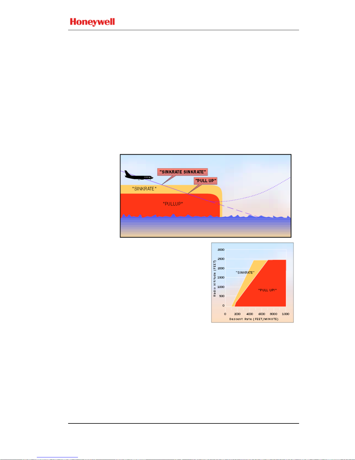
Mode 1 provides alerts for excessive descent rates with
respect to altitude AGL and is active for all phas es of flight.
This mode has inner and outer alert boundaries as illustrated
in the diagram and graph below.
Penetration of the outer boundary activates the EGPWS
caution lights and “SINKRATE, SINKRATE” alert
annunciation. Additional “SINKRATE, SINKRATE”
messages will occur for each 20% degradation in altitude.
During the time that the Sinkrate aural is inhibited and the
alert lamp is ON, the Mode 5 aural “Glid eslope” is allo wed to
annunciate for excessive glideslope deviation below the beam.
Penetration of the inner boundary activates the EGPWS
warning lights and changes the audio message to “PUL L UP”
which repeats continuously until the inner warning boundary
is exited.
Note:
“Pull Up” may be preceded by “Whoop, Whoop” in
some configurations based on the audio menu option selected.

Mark V and Mark VII EGPWS Pilot’s Guide
060-4241-000 System Descript ion
Rev H, August 2011 9
MODE 1
Continued
Glideslope
Deviation
Bias
If a valid ILS Glideslope front course is received and the
aircraft is above the glideslop e centerline, the outer (sinkrate)
boundary is adjusted to desensitize the sinkrate alerting. This
is to prevent unwanted alerts when the aircraft is safely
capturing the glideslope (or repositioning to the centerline)
from above the beam.
If the Aural Declutter feature is disabled, the Sinkrate alert
boundary remains fixed and the aural message “SINKRATE”
repeats continuously until the outer boundary is exited.
Envelope
Modulation
Through Envelope Modulation, both boundaries can be biased
to the right at certain airports to minimize nuisance alerts or
warnings.
Steep
Approach
Bias
The EGPWS offers a Steep Appro ach o ption for given aircraft
types that desensitizes the alert boundaries to permit steeper
than normal approaches without unwanted alerts. If Steep
Approach is selected (active) then the cockpit self-test is
inhibited if the aircraft is on the ground.
For Airbus A318/319/320/321 with version -226-226/-003 or
later, when Steep Approach is active
Mode 1 is disabled
below 130 ft and no other Mode 1 bias functions are allowed
to operate (Envelope Modulation or above the beam
Glideslope bias).
MODE 2
Excessive
Closure to
Terrain
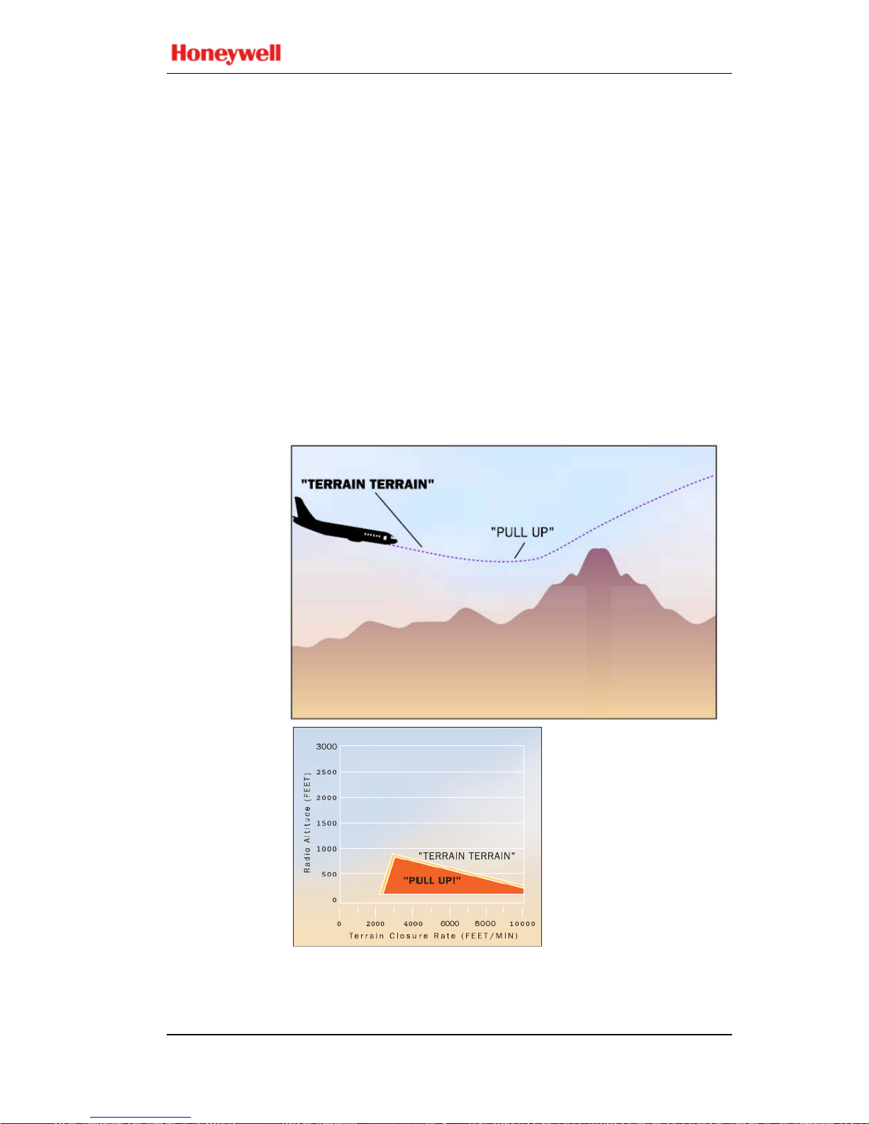
Mode 2 provides alerts to help protect the aircraft from
impacting the ground when rapidly rising terrain with respect
to the aircraft is detected. Mode 2 is based on Radio Altitude
and on how rapidly Radio Altitude is decreasing (closure
rate). Mode 2 exists in two forms, 2A and 2B.

Mark V and Mark VII EGPWS Pilot’s Guide
System Description 060-4241-000
10 Rev H, August 2011
MODE 2A
Mode 2A is active during climbout, cruise, and initial
approach (flaps not
in the landing configuration and the
aircraft not on glideslope centerline). If the aircraft penetrates
the Mode 2A caution envelope, the aural message
“TERRAIN, TERRAIN” is generated and cockpit EGPWS
caution lights will illuminate. If the aircraft conti
nues to
penetrate the envelope, the EGPWS warning lights will
illuminate and the aural warning message “PULL UP” is
repeated continuously until the warning envelope is exited.
Note:
“Pull Up” may be preceded by “Whoop, Whoop” in
some configurations based on the audio menu option selected.
Upon exiting the warning envelope, if terrain clearance
continues to decrease, the aural message “TERRAIN” will be
given until the terrain clearance stops decreasing. In addi tion,
the visual alert will remain on until the aircraft has gained 300
feet of barometric altitude, 45 seconds has elapsed, or landing
flaps or the flap override switch is activated.

Mark V and Mark VII EGPWS Pilot’s Guide
060-4241-000 System Descript ion
Rev H, August 2011 11
MODE 2A
Continued
The graph below shows how the upper boundary of the Mode
2 alert envelope varies as a fun ction of the aircraft speed. As
airspeed increases from 220 knots to 310 knots, the boundary
expands to provide increased alert times at higher airspeed s.
With version -210-210 and later models, the Mode 2A upper
limit is reduced to 1250 feet (950 feet with version -218-218
and later) for all airspeeds when the Terrain Alerting and
Display (TAD) function is enabled and available. This is due
to the enhanced alerting capability provided with TAD,
resulting from high integrity GPS Altitude and Geometric
Altitude data. The Mode 2A envelope is lowered in order to
reduce the potential for nuisance alerts during an approach.
This modification allows EGPWS operation to be compatible
with RADAR vectoring minimum terrain clearances.
Mark V and Mark VII EGPWS Pilot’s Guide
System Description 060-4241-000
12 Rev H, August 2011
MODE 2B
Mode 2B provides a desensitized alerting envelope to permit
normal landing approach maneuvers close to terrain without
unwanted alerts. Mode 2B is automatically selected with f laps
in the landing configuration (landing flaps or flap over-ride
selected) or when making an ILS approach with Glideslope
and Localizer deviation less than 2 dots. It is also active during
the first 60 seconds after takeoff.
With version -210-210 and later models, Mode 2B is selected
when the aircraft is within 5 NM (10 NM with version -218218 and later
) and 3500 feet of the destination airport
(independent of configuration) and the Terrain Alerting and
Display (TAD) function is enabled and available. This is due
to the enhanced alerting capability provided with TAD,
resulting from high integrity GPS Altitude and Geometric
Altitude data. The Mode 2B envelope is selected in order to
reduce the potential for nuisance alerts during an approach.
The graph above shows the Mode 2B envelope.
Mark V and Mark VII EGPWS Pilot’s Guide
060-4241-000 System Descript ion
Rev H, August 2011 13
MODE 2B
Continued
During an approach, if the aircraft penetrates the Mode 2B
envelope with either the gear or flaps not in the landing
configuration, the aural message “T ERRAIN, TERRAIN” is
generated and the EGPWS caution lights illuminate. If the
aircraft continues to penetrate the envelope, the EGPWS
warning lights illuminate and the aural message “PULL UP”
is repeated continuously until the warning envelope is exited.
If the aircraft penetrates the Mod e 2B en velop e with both gear
and flaps in the landing configuration, the aural “PULL UP”
messages are suppress ed and the aural messa ge “TERRAIN”
is repeated until the envelope is exited.
MODE 3
Altitude
Loss After
TakeOff
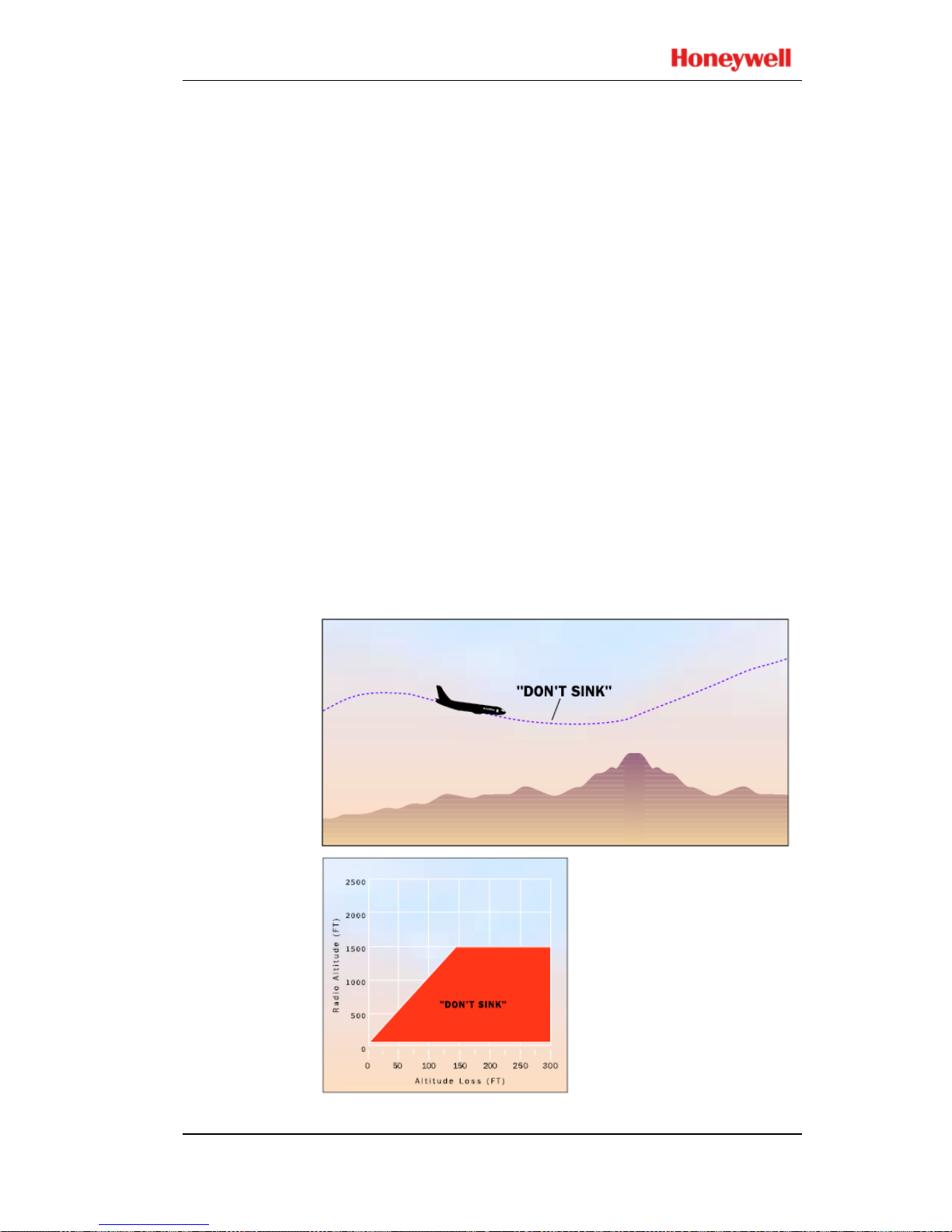
Mode 3 provides alerts for significant altitude loss after
takeoff or low altitude go-around (less than 245 feet AGL or
150 f
eet, depending on aircraft type) with gear or flaps not in
the landing configuration. The amount of altitude loss that is
permitted before an alert is given is a function of the height of
the aircraft above the terrain as shown below. This protection
is available until the EGPWS determines that the aircraft has
gained sufficient altitude or that it is no longer in the takeoff
phase of flight. Significant altitude loss after takeoff or during
a low altitude go-around activates the EGPWS caution lights
and the aural message “DON’T SINK, DON’T SINK”.

Mark V and Mark VII EGPWS Pilot’s Guide
System Description 060-4241-000
14 Rev H, August 2011
MODE 3
Continued
The aural message is enunciated twice for each 20%
degradation in altitude. Upon establishing a positive rate of
climb, the EGPWS caution lights extinguish and the aural
alert will cease.
If the Aural Declutter feature is disabled, the warning is
enunciated continuously until positive climb is established.
MODE 4
Unsafe
Terrain
Clearance
Mode 4 provides alerts for insufficient terrain clearance with
respect to phase of flight, configuration, and speed. Mode 4
exists in three forms, 4A, 4B, and 4C.
• Mode 4A is active during cruise and approach with the gear
and flaps not in the landing configuration.
• Mode 4B is active during cruise and approach with the gear
in the landing configuration and flaps not in the landing
configuration.
• Mode 4C is active during the takeoff phase of flight with
either the gear or flaps not in the landing configuration.
Mode 4 alerts activate the EGPWS caution lights and aural
messages.
To reduce nuisance alerts caused by over-
flying another
aircraft, the upper limit of the Mode 4A/B alerting curve can
be reduced (from 1000) to 800 feet. This occurs if the airplane
is above 250 knots with gear and flaps not in landing
configuration and a sudden change in Radio
Altitude is
detected. This is intended to eliminate nuisance alerts while
flying a holding pattern and an aircraft over-flight occurs
(with 1000 foot separation).
With version -210-
210 and later models, Mode 4 airspeed
expansion is disabled (upper limit held at lowest airspeed
limit) when the Terrain Alerting and Display (TAD) function
is enabled and available. This is d ue to the enhanced alerting
capability provided with TAD, resulting from high integrity
GPS Altitude and Geometric Altitu de data. This change to the
Mode 4 envelopes reduces the potential for nuisance alerts
when the aircraft is not in the landing configuration.
MODE 4A
Mode 4A is active during cruise and approach with gear and
flaps up. This provides alerting during cruise for inadvertent
flight into terrain where terrain is not rising significantly, or
the aircraft is not descending excessively. It also provides
alerting for protection against an unintentional gear-up
landing.
Mark V and Mark VII EGPWS Pilot’s Guide
060-4241-000 System Descript ion
Rev H, August 2011 15
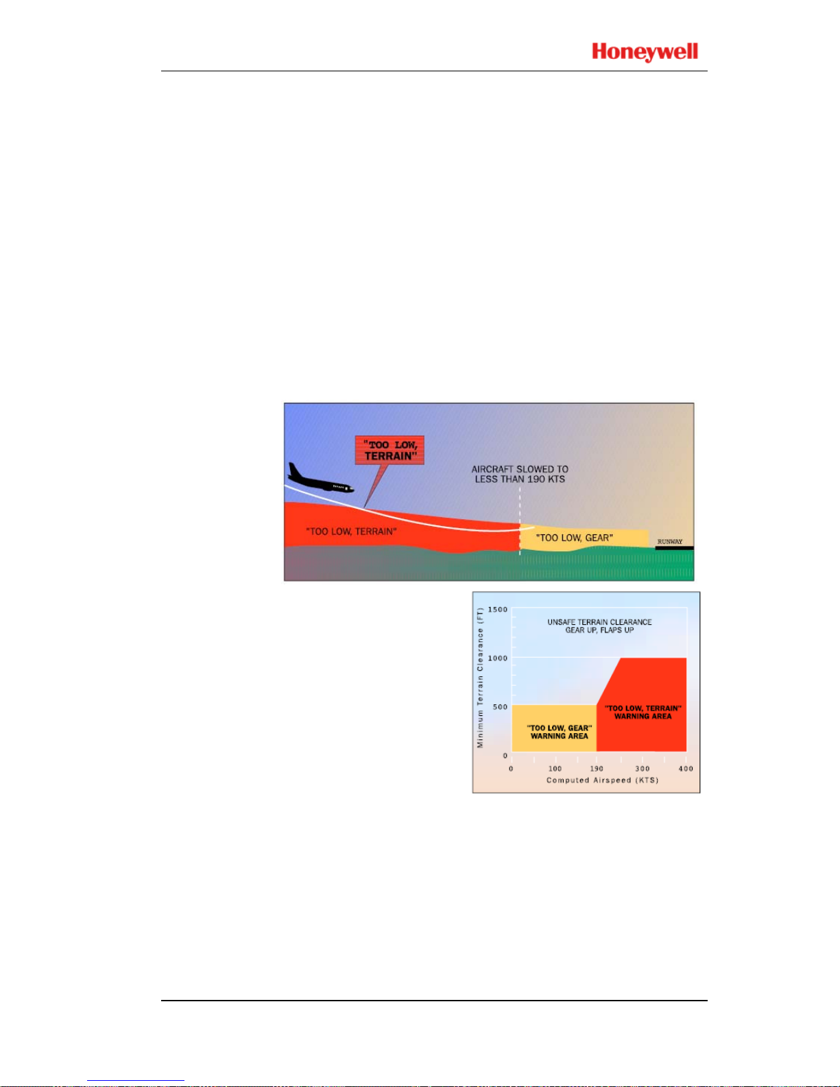
MODE 4A
Continued
Below 1000 feet AGL and above 190 knots airspeed, the
Mode 4A aural alert is “TOO LOW TER RAIN”. This alert
is dependent on aircraft speed such that the alert threshold is
ramped between 500 feet at 190 knots to 1000 feet at 250
knots.
Below 500 feet AGL and less than 190 knots airspeed, the
Mode 4A aural alert is “TOO LOW GEAR”.
For either Mode 4A alert, subsequent alert messages occu r for
each 20% degradation in altitude. EGPWS caution lights
extinguish and aural messages cease when th e Mode 4A alert
envelope is exited.
If the Aural Declutter feature is disabled, mode 4A alert
messages are repeated continuously until the Mode 4A
envelope is exited.
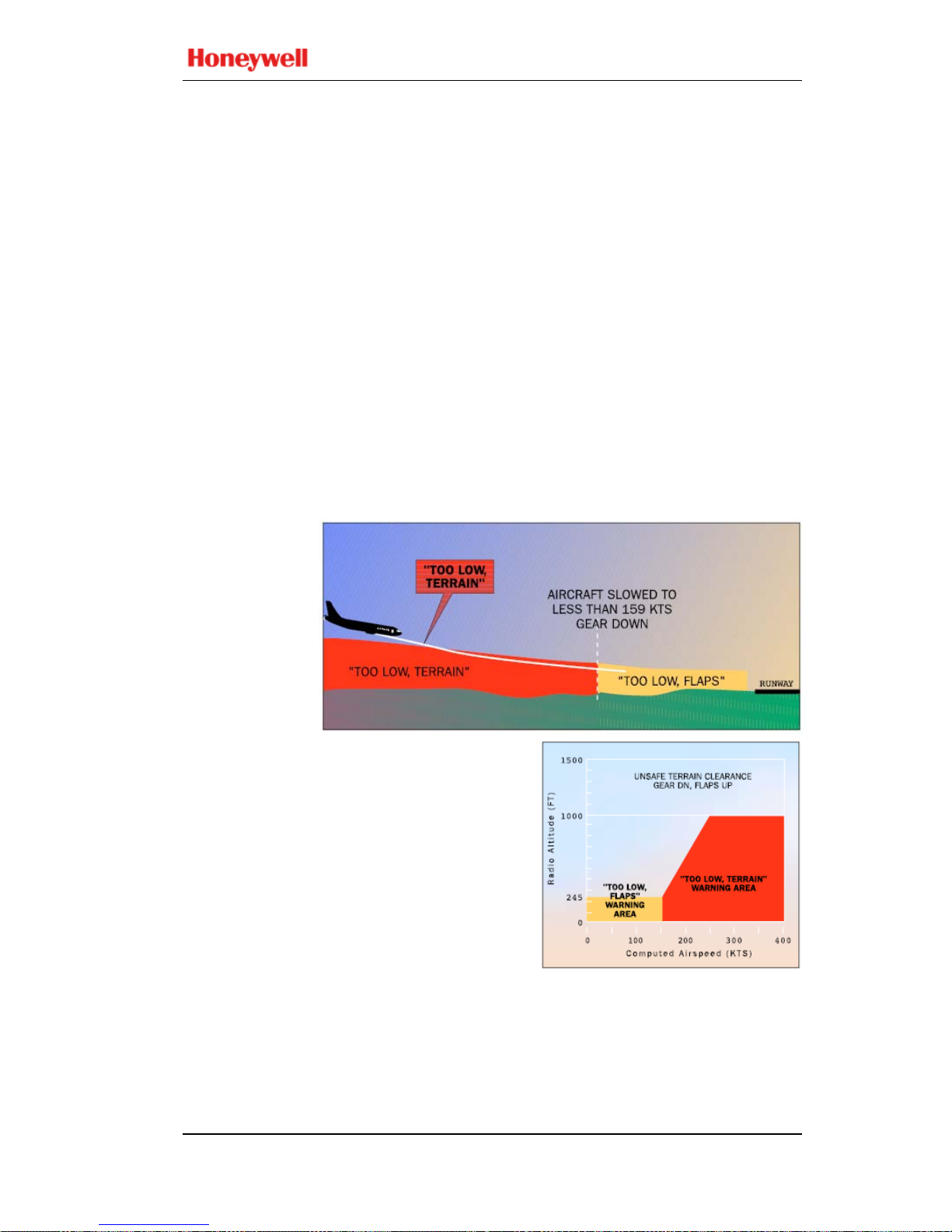
MODE 4B
Mode 4B is active during cruise and approach, with gear
down and flaps not in the landing configuration.
Below 1000 feet AGL and above 159 knots (185 knots for
Boeing 747-8) airspeed, the Mode 4B aural alert is “TOO
LOW TERRAIN”. This alert is dependent on aircraft speed
such that the alert threshold is ramped between 245 feet at 159
knots (185 knots for Boeing 747-8) to 1000 feet at 250 knots.
Mark V and Mark VII EGPWS Pilot’s Guide
System Description 060-4241-000
16 Rev H, August 2011
MODE 4B
Continued
Below 245 feet AGL and less than 159 knots (185 knots for
Boeing 747-8) airspeed, the Mode 4B aural alert is “TOO
LOW FLAPS”. For turboprop and selected turbofan aircraft,
the “TOO LOW FLAPS” warning curve is lowered to 150
feet AGL and less than 148 knots.
If desired, the pilot may disable the “TOO LOW FLAPS”
alert by engaging the Flap Override switch (if installed). This
precludes or silences the Mode 4B flap alert until reset by the
pilot.
If the aircraft’s Radio Altitude decreases to the value of the
Minimum Terrain Clearance (MTC), the EGPWS caution
illuminates and the aural message “TOO LOW TERRAIN”
is enunciated.
For either Mode 4B alert, subs equent alert messages occu r for
each 20% degradation in altitude. EGPWS caution lights
extinguish and aural messages cease when the Mode 4B alert
envelope is exited.
If the Aural Declutter
feature is disabled, mode
4B alert messages are
repeated continuously
until the Mode 4B
envelope is exited.
MODE 4C
The Mode 4C alert is intended to prevent inadvertent
controlled flight into the ground during takeoff climb into
terrain that produces insufficient closure rate for a Mode 2
alert. After takeoff, Mode 4A and 4B provide this protection.

Mark V and Mark VII EGPWS Pilot’s Guide
060-4241-000 System Descript ion
Rev H, August 2011 17
MODE 4C
Continued
Mode 4C is based on an EGPWS compu ted Minimum Terrain
Clearance (MTC) floor that increases with Radio Altitude. It
is active after takeoff when the gear or flaps are not in the
landing configuration. It is also active during a low altitude
go-around if the aircraft has descended below 245 feet AGL
(or 150 feet depending on aircraft type).
At takeoff the Minimum Terrain Clearance (MTC) is zero
feet. As the aircraft ascends the MTC is increased to 75% of
the aircraft’s Radio Altitude (averaged over the previous 15
seconds).
This value is not allowed to decrease and is limited to 500 feet
AGL for airspeed less than 190 knots. Beginning at 190 knots,
the MTC increases linearly to the limit of 1000 feet at 250
knots.
If the aircraft’s Radio Altitude decreases to the value of the
MTC, the EGPWS caution illuminates an d the aural message
“TOO LOW TERRAIN” is enunciated.
EGPWS caution lights extinguish and aural messages cease
when the Mode 4C alert envelope is exited.
If the Aural Declutter feature is disabled, mode 4C alert
messages
are repeated continuously until the Mode 4C
envelope is exited.

Mark V and Mark VII EGPWS Pilot’s Guide
System Description 060-4241-000
18 Rev H, August 2011
MODE 5
Excessive
Deviation
Below
Glideslope
Mode 5 provides two levels of alerting for when the aircraft
descends below glideslope, resulting in activation of EGPWS
caution lights and aural messages.
The first level alert occurs when below 1000 feet Radio
Altitude and the aircraft is 1.3 dots or greater below the beam.
This turns on the caution lights and is called a “soft” alert
because the audio message “GLIDESLOPE” is enunciated at
half volume. 20% increases in the belo w glideslope deviation
cause additional “GLIDESLOPE” messages en unciated at a
progressively faster rate.
The second level alert occurs when below 300 feet Radio
Altitude with 2 dots or greater glideslope deviation. This is
called a “hard” alert because a louder “GLIDESLOPE,
GLIDESLOPE” message is enunciated every 3 seconds
continuing until the “hard” envelope is exited. The caution
lights remain on until a glideslope deviation less than 1.3 dots
is achieved.
To avoid unwanted Below Glideslope alerts when capturing
the localizer between 500 and 1000 feet AGL, alerting is
varied in the following ways:
• Below Glideslope alerts are enabled only if the localizer is
within 2 dots, landing gear and flaps are selected,
Glideslope Cancel is not active, and a front course
approach is deter m i ne d.

Mark V and Mark VII EGPWS Pilot’s Guide
060-4241-000 System Descript ion
Rev H, August 2011 19
MODE 5
Continued
• The upper altitude limit for the alert is modulated with
vertical speed. For descent rates ab ove 500 FPM, the u pper
limit is set to the normal 10 00 feet AGL. For descent rates
lower than 500 FPM, the upper limit is desensitized
(reduced) to a minimum of 500 feet AGL.
Additionally, both alert levels are desensitized below 150 feet
AGL, to allow for normal beam variations nearer the ground,
and reduce the possibility of nuisance alerts.
If the Aural Declutter feature is disabled, messages are
repeated continuously until the Mode 5 envelope is exited.
Mode 5 alerts can be canceled by pressing the Glideslope
Cancel switch (if installed). The EGPWS will interpret this
switch one of two ways depending on the installation
configuration.
• A standard glideslope cancel switch allows for manually
canceling Mode 5 alerting any time below 2000 feet AGL.
This is automatically reset when the aircraft descends
below 50 feet or climbs above 2000 feet AGL (1000 feet
AGL for current Boeing production aircraft).
• An alternate glideslope cancel switch allows for manu ally
canceling Mode 5 alerting at any time and any altitude. The
cancel is reset by again pressing the cancel switch, or
automatically if gear or flaps ar e raised, or the ai rcraf t is on
the ground. Due to the nature of the alternate cancel switch,
this method requires that there be a cockpit annunciation
that glideslope cancel is in effect (this configuration is
currently not allowed on aircraft operating under FAA part
121 rules).
EGPWS Mode 5 alerts are inhibited during backcourse
approaches to prevent nuisance alerts due to false fly up lobes
from the Glideslope. The EGPWC determines a backcourse
approach if either: 1) the aircraft’s magnetic track is greater
than 90 degrees from the runways approach course, or 2) a
glideslope inhibit discrete is set.
MODE 6
Advisory
Callouts
Mode 6 provides EGPWS advisory callouts based on the
menu-selected option established at in
stallation (set by
program pin configuration). These callouts consist of
predefined Radio Altitude based voice callouts or tones and an
excessive bank angle advisory. There is no visual alerting
provided with these callouts.

Mark V and Mark VII EGPWS Pilot’s Guide
System Description 060-4241-000
20 Rev H, August 2011
MODE 6
Continued
Altitude
Callouts
The following is a list of each of the possible altitude callouts
or tones:
CALLOUT Occurs at (feet AGL)
“RADIO ALTIMETER” ............................................ 2500
“TWENTY FIVE HUNDRED” ................................ 2500
“ONE THOUSAND” ................................................ 1000
a
“EIGHT HUNDRED” ................................................. 800
a
“FIVE HUNDRED” .................................................... 500
a
Five Hundred Tone (2 second 960 Hz) ....................... 500
“FOUR HUNDRED” .................................................. 400
“THREE HUNDRED” ................................................ 300
“TWO HUNDRED” ................................................... 200
“APPROACHING MINIMUMS” ......................... DH+80
b
“APPROACHING DECISION HEIGHT” ......... DH+100
b
“PLUS HUNDRED” ........................................... DH+100
b
“FIFTY ABOVE” ................................................. DH+50
b
“MINIMUM” .............................................................. DH
b
“MINIMUMS” ............................................................ DH
b
“MINIMUMS - MINIMUMS” ................................... DH
b
“DECISION HEIGHT” ............................................... DH
b
“DECIDE” .................................................................. DH
b
“ONE HUNDRED” .................................................... 100
One Hundred Tone (2 second 700 Hz) ........................ 100
“EIGHTY” .................................................................... 80
“SIXTY” ....................................................................... 60
“FIFTY” ........................................................................ 50
“FORTY” ...................................................................... 40
“TH IRTY FIV E ” .......................................................... 35
Thirty Five Tone (1 second 1400 Hz) ........................... 35
“THIRTY” .................................................................... 30
“TWENTY” .................................................................. 20
Twenty Tone (1/2 second 2800 Hz) .............................. 20
“TEN” ............................................................................ 10
“FIVE” ............................................................................. 5
a. May be Barometric Altitude above the field elevatio n for some aircraft types.
b.
May be MDA or DH for some aircraft types.

Mark V and Mark VII EGPWS Pilot’s Guide
060-4241-000 System Descript ion
Rev H, August 2011 21
MODE 6
Continued
In some cases a callout is stated twice (e.g., “MINIMUMS,
MINIMUMS”) but in all cases a given altitude callout is only
annunciated once per approach.
Decision Height (DH) based callouts (Approaching
Minimums, Minimums, etc.) require the landing gear to be
down and occur when descending through the Radio Altitude
corresponding to the selected DH. These also have priority
over other altitude callouts when overlapping. For example, if
DH is set to 200 and both “TWO HUNDRED” and
MINIMUMS” are valid callouts, then only “MINIMUMS”
will be called out at 200 feet AGL.
DH plus based callouts (e.g., Approaching Minimums) are
only applicable for aircraft providing a Decision Height
altitude to the EGPWS. Consequently, not all EGPWS
installations can utilize these callout options.
Due to the variety of altitude callout choices available, it is
not possible to identify every combination in this guide. Refer
to an appropriate Airplane Flight Manual or EGPWS Airplane
Flight Manual Supplement for callout identification in a
specific application or contact Honeywell.
Smart
500 Foot
Callout
Another feature available in the Altitude Callouts (options) is
a “Smart 500” foot callout. When selected , this callout assists
pilots during a non-precision approach by enunciating “FIVE
HUNDRED” feet in addition to any other altitude callout
discussed above. The EGPWS determines a non-precision
approach when Glideslope or Localizer is greater than 2 dots
deviation (valid or not) or a back-course approach is detected
or Glideslope Cancel is selected.
This feature has the distinction of adding the 500-foot callout
during non-precision approaches and removing the 500-foot
callout on precision approaches when part of the callout
option.
Mark V and Mark VII EGPWS Pilot’s Guide
System Description 060-4241-000
22 Rev H, August 2011
MODE 6
Continued
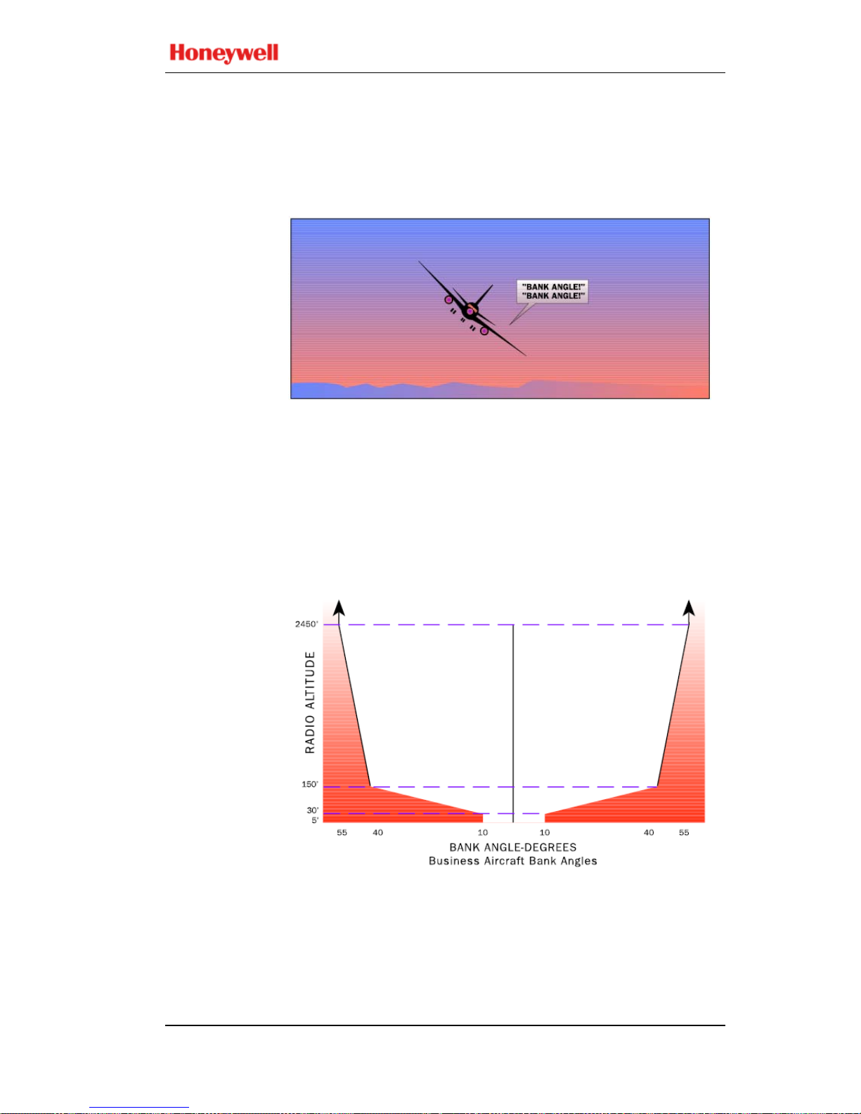
Bank Angle
Callout
The callout “BANK ANGLE, BANK ANGLE” advises of
an excessive roll
angle. The EGPWS provides several
excessive bank angle envelopes supporting Air Transport,
Business, or Military aircraft types (only Air Transport and
Business aircraft types are addressed below).
Business
Bank Angle
One envelope is defined for turbo-prop and business jet
aircraft (see graph below). Bank angles in excess of:
• ±10° between 5 and 30 feet,
• ±10 to 40° between 30 and 150 feet,
• ±40 to 55° between 150 and 2450 feet,
• 55° above 2450 feet
produce the bank angle advisory (shaded area). Bank angle
advisories are inhibited below 5 feet.
Mark V and Mark VII EGPWS Pilot’s Guide
060-4241-000 System Descript ion
Rev H, August 2011 23
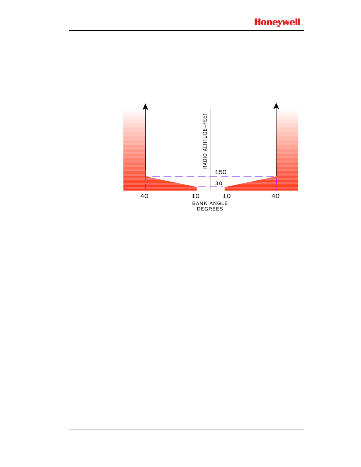
MODE 6
Air Transport
Bank Angle
Three envelopes are defined f or Air Transport aircraft. These
are identified as Basic Ban k Angle, Bank Angle Op tion 1, and
Bank Angle Option 2 advisories.
The Air Transport Basic Bank Angle limits are similar to the
Business Aircraft Bank Angle limits except above 150 feet the
bank limit remains at 40 as shown below.
Bank Angle Option 1 provides bank angle advisory thresholds
at 35, 40, and 45 independent of altitude. In this case, an
advisory at 35 is provided and another is not given unless 40
is exceeded and then again only if 45 is exceeded. If the roll
rate exceeds the audio callout time, then the bypassed limit is
not indicated.
Also, when any one of the thresholds is exceeded, the bank
angle must reduce below 30 for the process to reset before
additional Bank Angle Advisories can be provided.
For example, if greater than 40 is obtained before the 35
callout is complete, another callout is provided only if 45 is
obtained or the bank angle is reduced to less than 30 and then
again increases to 35.
Bank Angle Option 2 provides a combination of the Basic
Bank Angle and Bank angle Option 1. The Basic Bank Angle
limits are provided below 130 feet, and Bank Angle Option 1
is provided above 130 feet.
Any one of these three Bank Angle limits can be selected by
program pin if the aircraft type is defined as an Air Transport
aircraft.
Mark V and Mark VII EGPWS Pilot’s Guide
System Description 060-4241-000
24 Rev H, August 2011
MODE 7
Windshear
Alerting
Mode 7 is designed to provide alerts if the aircraft encounters
windshear. Two alerting envelopes provide either a
Windshear Caution alert or a Windshear Warning alert each
with distinctive aural and visual indications to the flight crew.
EGPWS windshear is provided for certain (not all) aircraft
types and is a function of certain additionally required input
signals and enabled internal detection algorithms. These are
established during the initial installation and addressed in the
appropriate Airplane Flight Manual (AFM) or EGPWS
Airplane Flight Manual Supplement (AFMS).
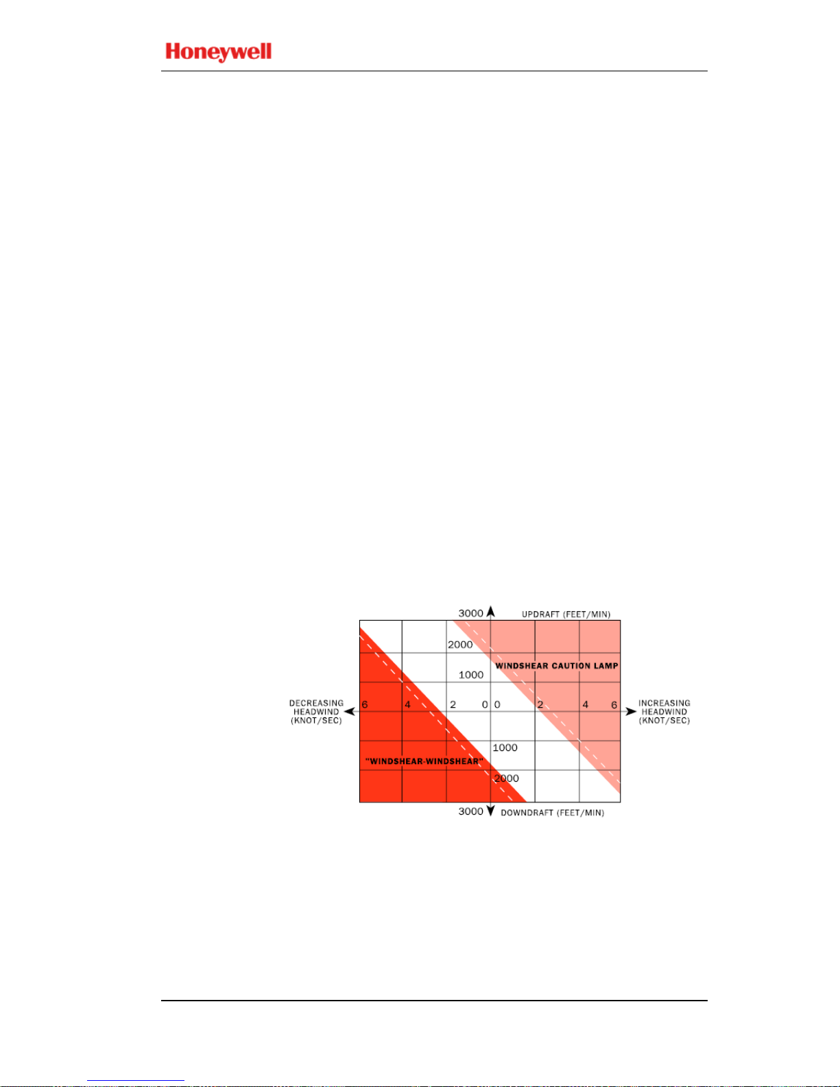
Windshear
Caution
Windshear Caution alerts are given if an increasing headwind
(or decreasing tailwind) and/or a severe updraft exceeds the
defined threshold. These are characteristic of conditions
preceding an encounter with a microburst.
A Win
dshear Caution (if enabled) results in illumination of
amber Windshear Caution lights and may (if separately
enabled) also be accompanied by the aural message
“CAUTION, WINDSHEAR”. The lights remain on for as
long as the aircraft is exposed to conditions in excess of the
caution alert threshold. The Windshear Caution envelope is
illustrated in the figure below.
The Windshear Caution alerting can be disabled by EGPWS
program pin selection so that only Windshear Warning alerts
are provided.
Windshear
Warning
Windshear Warning alerts are given if a decreasing headwin d
(or increasing tailwind) and/or a severe downdraft exceeds the
defined threshold. These are characteristic of conditions
within or exiting an encounter with a microburst.
 Loading...